Page 1105 of 3502
DTC P0745 LINE PRESSURE SOLENOID VALVE
CVT-99
D
E
F
G
H
I
J
K
L
MA
B
CVT
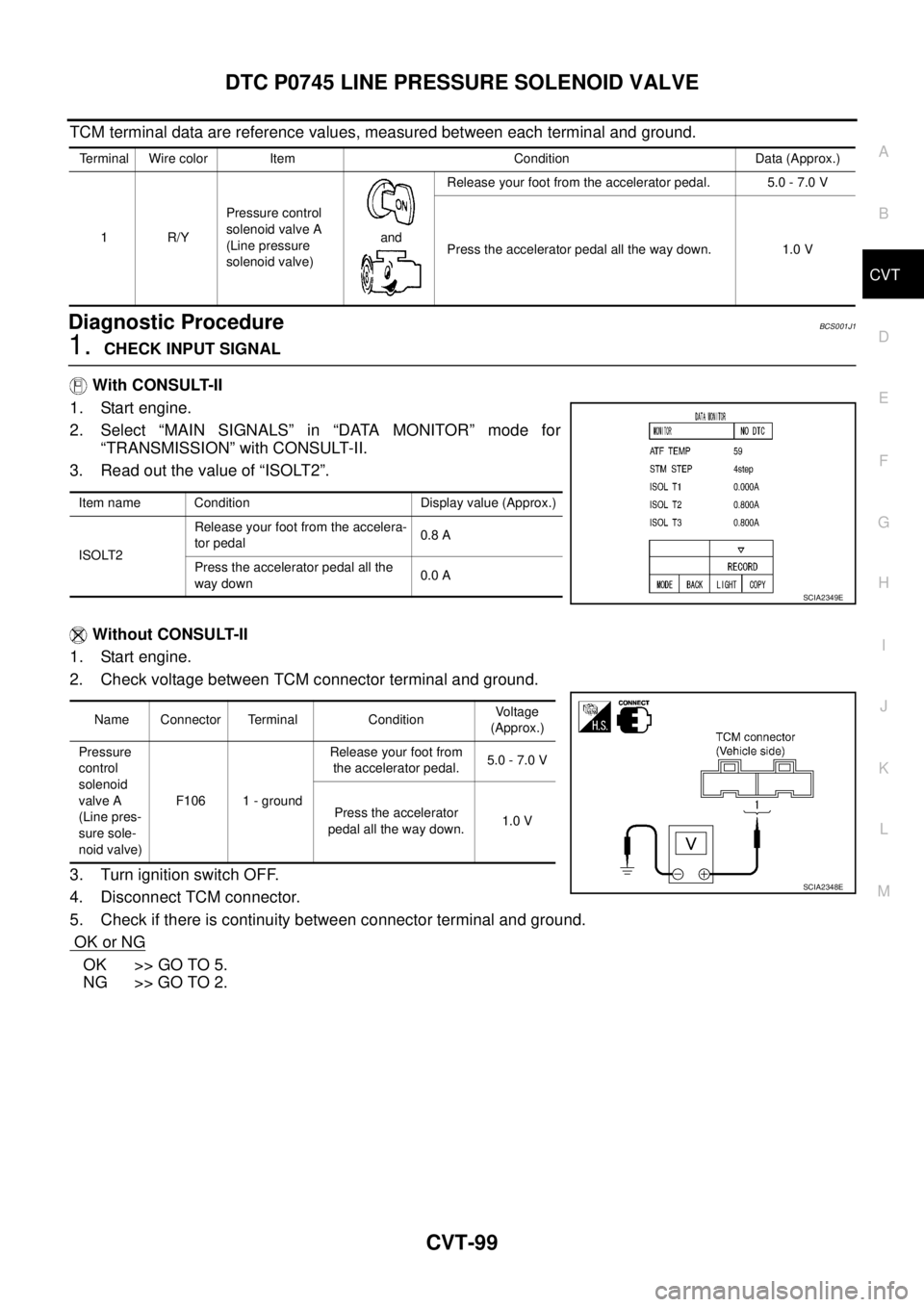
TCM terminal data are reference values, measured between each terminal and ground.
Diagnostic ProcedureBCS001J1
1. CHECK INPUT SIGNAL
With CONSULT-II
1. Start engine.
2. Select “MAIN SIGNALS” in “DATA MONITOR” mode for
“TRANSMISSION” with CONSULT-II.
3. Read out the value of “ISOLT2”.
Without CONSULT-II
1. Start engine.
2. Check voltage between TCM connector terminal and ground.
3. Turn ignition switch OFF.
4. Disconnect TCM connector.
5. Check if there is continuity between connector terminal and ground.
OK or NG
OK >> GO TO 5.
NG >> GO TO 2.
Terminal Wire color Item Condition Data (Approx.)
1R/YPressure control
solenoid valve A
(Line pressure
solenoid valve)and Release your foot from the accelerator pedal. 5.0 - 7.0 V
Press the accelerator pedal all the way down. 1.0 V
Item name Condition Display value (Approx.)
ISOLT2Release your foot from the accelera-
tor pedal0.8 A
Press the accelerator pedal all the
way down0.0 A
SCIA2349E
Name Connector Terminal ConditionVoltage
(Approx.)
Pressure
control
solenoid
valve A
(Line pres-
sure sole-
noid valve)F106 1 - groundRelease your foot from
the accelerator pedal.5.0 - 7.0 V
Press the accelerator
pedal all the way down.1.0 V
SCIA2348E
Page 1109 of 3502
DTC P0746 PRESSURE CONTROL SOLENOID A PERFORMANCE (LINE PRES-
SURE SOLENOID VALVE)
CVT-103
D
E
F
G
H
I
J
K
L
MA
B
CVT
Diagnostic ProcedureBCS001J8
1. CHECK INPUT SIGNAL
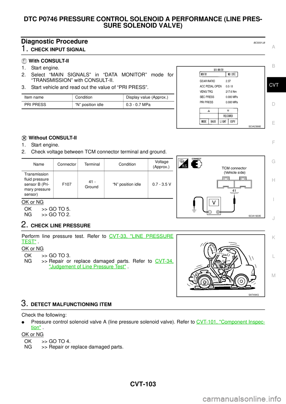
With CONSULT-II
1. Start engine.
2. Select “MAIN SIGNALS” in “DATA MONITOR” mode for
“TRANSMISSION” with CONSULT-II.
3. Start vehicle and read out the value of “PRI PRESS”.
Without CONSULT-II
1. Start engine.
2. Check voltage between TCM connector terminal and ground.
OK or NG
OK >> GO TO 5.
NG >> GO TO 2.
2. CHECK LINE PRESSURE
Perform line pressure test. Refer to CVT-33, "
LINE PRESSURE
TEST" .
OK or NG
OK >> GO TO 3.
NG >> Repair or replace damaged parts. Refer to CVT-34,
"Judgement of Line Pressure Test" .
3. DETECT MALFUNCTIONING ITEM
Check the following:
�Pressure control solenoid valve A (line pressure solenoid valve). Refer to CVT-101, "Component Inspec-
tion" .
OK or NG
OK >> GO TO 4.
NG >> Repair or replace damaged parts.
Item name Condition Display value (Approx.)
PRI PRESS “N” position idle 0.3 - 0.7 MPa
SCIA2366E
Name Connector Terminal Condition Voltage
(Approx.)
Transmission
fluid pressure
sensor B (Pri-
mary pressure
sensor) F107 41 -
Ground“N” position idle 0.7 - 3.5 V
SCIA1922E
SAT494G
Page 1112 of 3502
CVT-106
DTC P0776 PRESSURE CONTROL SOLENOID B PERFORMANCE (SEC PRES-
SURE SOLENOID VALVE)
Diagnostic ProcedureBCS001JE
1. CHECK INPUT SIGNAL
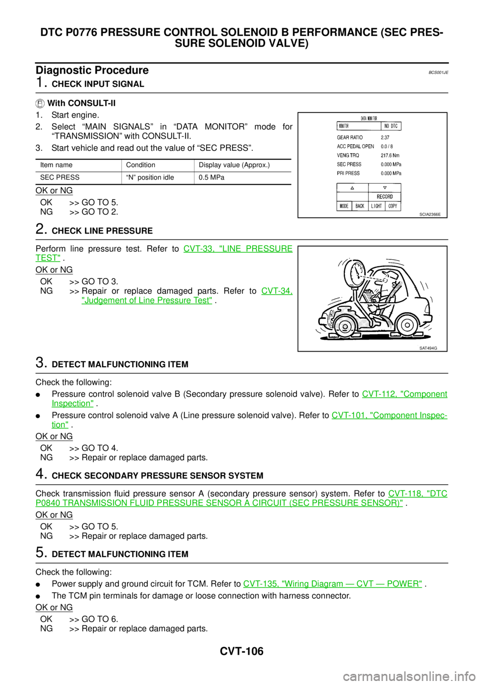
With CONSULT-II
1. Start engine.
2. Select “MAIN SIGNALS” in “DATA MONITOR” mode for
“TRANSMISSION” with CONSULT-II.
3. Start vehicle and read out the value of “SEC PRESS”.
OK or NG
OK >> GO TO 5.
NG >> GO TO 2.
2. CHECK LINE PRESSURE
Perform line pressure test. Refer to CVT-33, "
LINE PRESSURE
TEST" .
OK or NG
OK >> GO TO 3.
NG >> Repair or replace damaged parts. Refer to CVT-34,
"Judgement of Line Pressure Test" .
3. DETECT MALFUNCTIONING ITEM
Check the following:
�Pressure control solenoid valve B (Secondary pressure solenoid valve). Refer to CVT-112, "Component
Inspection" .
�Pressure control solenoid valve A (Line pressure solenoid valve). Refer to CVT-101, "Component Inspec-
tion" .
OK or NG
OK >> GO TO 4.
NG >> Repair or replace damaged parts.
4. CHECK SECONDARY PRESSURE SENSOR SYSTEM
Check transmission fluid pressure sensor A (secondary pressure sensor) system. Refer to CVT-118, "
DTC
P0840 TRANSMISSION FLUID PRESSURE SENSOR A CIRCUIT (SEC PRESSURE SENSOR)" .
OK or NG
OK >> GO TO 5.
NG >> Repair or replace damaged parts.
5. DETECT MALFUNCTIONING ITEM
Check the following:
�Power supply and ground circuit for TCM. Refer to CVT-135, "Wiring Diagram — CVT — POWER" .
�The TCM pin terminals for damage or loose connection with harness connector.
OK or NG
OK >> GO TO 6.
NG >> Repair or replace damaged parts.
Item name Condition Display value (Approx.)
SEC PRESS “N” position idle 0.5 MPa
SCIA2366E
SAT494G
Page 1116 of 3502
CVT-110
DTC P0778 PRESSURE CONTROL SOLENOID B ELECTRICAL (SEC PRES-
SURE SOLENOID VALVE)
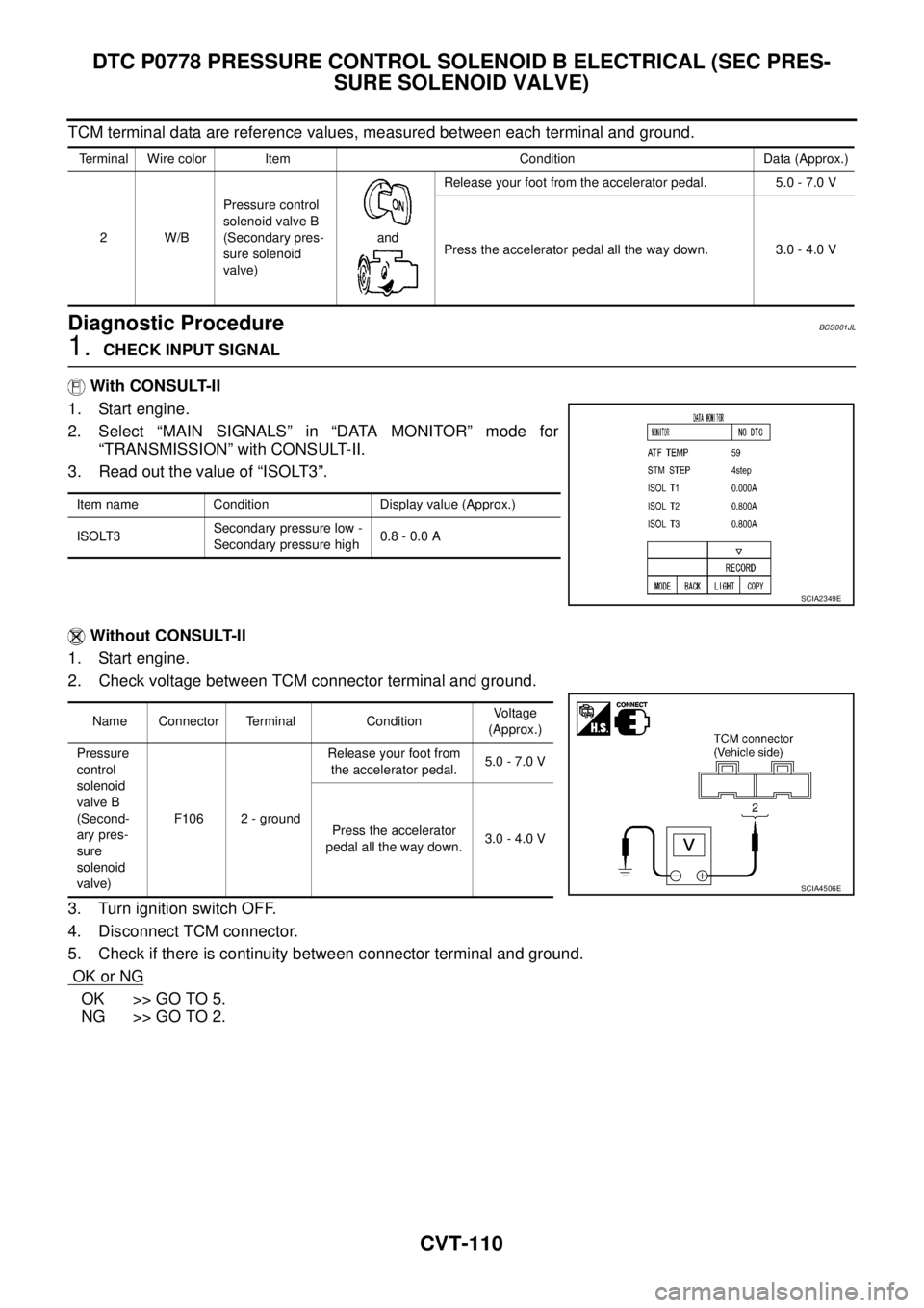
TCM terminal data are reference values, measured between each terminal and ground.
Diagnostic ProcedureBCS001JL
1. CHECK INPUT SIGNAL
With CONSULT-II
1. Start engine.
2. Select “MAIN SIGNALS” in “DATA MONITOR” mode for
“TRANSMISSION” with CONSULT-II.
3. Read out the value of “ISOLT3”.
Without CONSULT-II
1. Start engine.
2. Check voltage between TCM connector terminal and ground.
3. Turn ignition switch OFF.
4. Disconnect TCM connector.
5. Check if there is continuity between connector terminal and ground.
OK or NG
OK >> GO TO 5.
NG >> GO TO 2.
Terminal Wire color Item Condition Data (Approx.)
2W/BPressure control
solenoid valve B
(Secondary pres-
sure solenoid
valve)andRelease your foot from the accelerator pedal. 5.0 - 7.0 V
Press the accelerator pedal all the way down. 3.0 - 4.0 V
Item name Condition Display value (Approx.)
ISOLT3Secondary pressure low -
Secondary pressure high0.8 - 0.0 A
SCIA2349E
Name Connector Terminal ConditionVoltage
(Approx.)
Pressure
control
solenoid
valve B
(Second-
ary pres-
sure
solenoid
valve)F106 2 - groundRelease your foot from
the accelerator pedal.5.0 - 7.0 V
Press the accelerator
pedal all the way down.3.0 - 4.0 V
SCIA4506E
Page 1121 of 3502
DTC P0826 MANUAL MODE SWITCH CIRCUIT
CVT-115
D
E
F
G
H
I
J
K
L
MA
B
CVT
TCM terminal data are reference values, measured between each terminal and ground.
Diagnostic ProcedureBCS001JU
1. CHECK CAN COMMUNICATION LINE
Perform the self-diagnosis check. Refer to CVT-47, "
SELF-DIAGNOSTIC RESULT MODE" .
Is any malfunction of the
“U1000 CAN COMM CIRCUIT” indicated?
YES >> Check CAN communication line. Refer to CVT-53, "DTC U1000 CAN COMMUNICATION LINE" .
NO >> GO TO 2.
2. CHECK MANUAL MODE SWITCH CIRCUIT
With CONSULT-II
1. Turn ignition switch ON. (Do not start engine.)
2. Select “ECU INPUT SIGNALS” in “DATA MONITOR” mode for
“TRANSMISSION” with CONSULT-II.
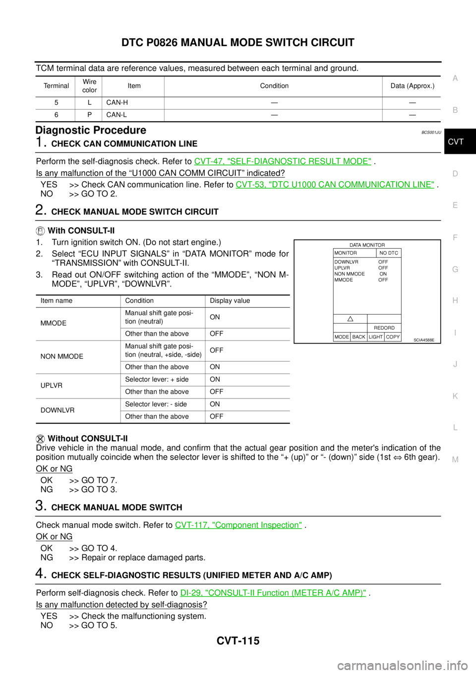
3. Read out ON/OFF switching action of the “MMODE”, “NON M-
MODE”, “UPLVR”, “DOWNLVR”.
Without CONSULT-II
Drive vehicle in the manual mode, and confirm that the actual gear position and the meter's indication of the
position mutually coincide when the selector lever is shifted to the “+ (up)” or “- (down)” side (1st ⇔ 6th gear).
OK or NG
OK >> GO TO 7.
NG >> GO TO 3.
3. CHECK MANUAL MODE SWITCH
Check manual mode switch. Refer to CVT-117, "
Component Inspection" .
OK or NG
OK >> GO TO 4.
NG >> Repair or replace damaged parts.
4. CHECK SELF-DIAGNOSTIC RESULTS (UNIFIED METER AND A/C AMP)
Perform self-diagnosis check. Refer to DI-29, "
CONSULT-II Function (METER A/C AMP)" .
Is any malfunction detected by self-diagnosis?
YES >> Check the malfunctioning system.
NO >> GO TO 5.
TerminalWire
colorItem Condition Data (Approx.)
5 L CAN-H — —
6 P CAN-L — —
Item name Condition Display value
MMODEManual shift gate posi-
tion (neutral)ON
Other than the above OFF
NON MMODEManual shift gate posi-
tion (neutral, +side, -side)OFF
Other than the above ON
UPLVRSelector lever: + side ON
Other than the above OFF
DOWNLVRSelector lever: - side ON
Other than the above OFF
SCIA4588E
Page 1126 of 3502
CVT-120
DTC P0840 TRANSMISSION FLUID PRESSURE SENSOR A CIRCUIT (SEC
PRESSURE SENSOR)
TCM terminal data are reference values, measured between each terminal and ground.
Diagnostic ProcedureBCS001K2
1. CHECK INPUT SIGNAL
With CONSULT-II
1. Start engine.
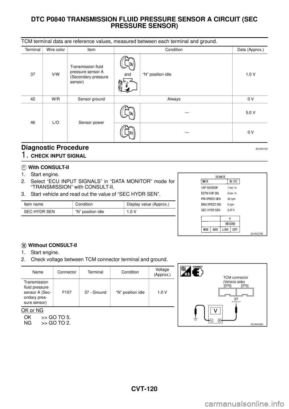
2. Select “ECU INPUT SIGNALS” in “DATA MONITOR” mode for
“TRANSMISSION” with CONSULT-II.
3. Start vehicle and read out the value of “SEC HYDR SEN”.
Without CONSULT-II
1. Start engine.
2. Check voltage between TCM connector terminal and ground.
OK or NG
OK >> GO TO 5.
NG >> GO TO 2.
Terminal Wire color Item Condition Data (Approx.)
37 V/WTransmission fluid
pressure sensor A
(Secondary pressure
sensor)and “N” position idle 1.0 V
42 W/R Sensor ground Always 0 V
46 L/O Sensor power— 5.0 V
—0 V
Item name Condition Display value (Approx.)
SEC HYDR SEN “N” position idle 1.0 V
SCIA2279E
Name Connector Terminal ConditionVoltage
(Approx.)
Transmission
fluid pressure
sensor A (Sec-
ondary pres-
sure sensor)F107 37 - Ground “N” position idle 1.0 V
SCIA4508E
Page 1127 of 3502
DTC P0840 TRANSMISSION FLUID PRESSURE SENSOR A CIRCUIT (SEC
PRESSURE SENSOR)
CVT-121
D
E
F
G
H
I
J
K
L
MA
B
CVT
2. CHECK SENSOR POWER AND SENSOR GROUND
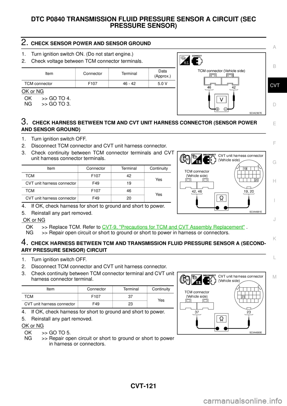
1. Turn ignition switch ON. (Do not start engine.)
2. Check voltage between TCM connector terminals.
OK or NG
OK >> GO TO 4.
NG >> GO TO 3.
3. CHECK HARNESS BETWEEN TCM AND CVT UNIT HARNESS CONNECTOR (SENSOR POWER
AND SENSOR GROUND)
1. Turn ignition switch OFF.
2. Disconnect TCM connector and CVT unit harness connector.
3. Check continuity between TCM connector terminals and CVT
unit harness connector terminals.
4. If OK, check harness for short to ground and short to power.
5. Reinstall any part removed.
OK or NG
OK >> Replace TCM. Refer to CVT-9, "Precautions for TCM and CVT Assembly Replacement" .
NG >> Repair open circuit or short to ground or short to power in harness or connectors.
4. CHECK HARNESS BETWEEN TCM AND TRANSMISSION FLUID PRESSURE SENSOR A (SECOND-
ARY PRESSURE SENSOR) CIRCUIT
1. Turn ignition switch OFF.
2. Disconnect TCM connector and CVT unit harness connector.
3. Check continuity between TCM connector terminal and CVT unit
harness connector terminal.
4. If OK, check harness for short to ground and short to power.
5. Reinstall any part removed.
OK or NG
OK >> GO TO 5.
NG >> Repair open circuit or short to ground or short to power
in harness or connectors.
Item Connector TerminalData
(Approx.)
TCM connector F107 46 - 42 5.0 V
SCIA2367E
Item Connector Terminal Continuity
TCM F107 42
Ye s
CVT unit harness connector F49 19
TCM F107 46
Ye s
CVT unit harness connector F49 20
SCIA4681E
Item Connector Terminal Continuity
TCM F107 37
Ye s
CVT unit harness connector F49 23
SCIA4690E
Page 1130 of 3502
CVT-124
DTC P0841 PRESSURE SENSOR FUNCTION
Diagnostic ProcedureBCS001K8
1. CHECK CAN COMMUNICATION LINE
Perform the self-diagnosis. Refer to CVT-47, "
SELF-DIAGNOSTIC RESULT MODE" .
Is any malfunction of the
“U1000 CAN COMM CIRCUIT” indicated?
YES >> Check CAN communication line. Refer to CVT-53, "DTC U1000 CAN COMMUNICATION LINE" .
NO >> GO TO 2.
2. CHECK INPUT SIGNALS
With CONSULT-II
1. Start engine.
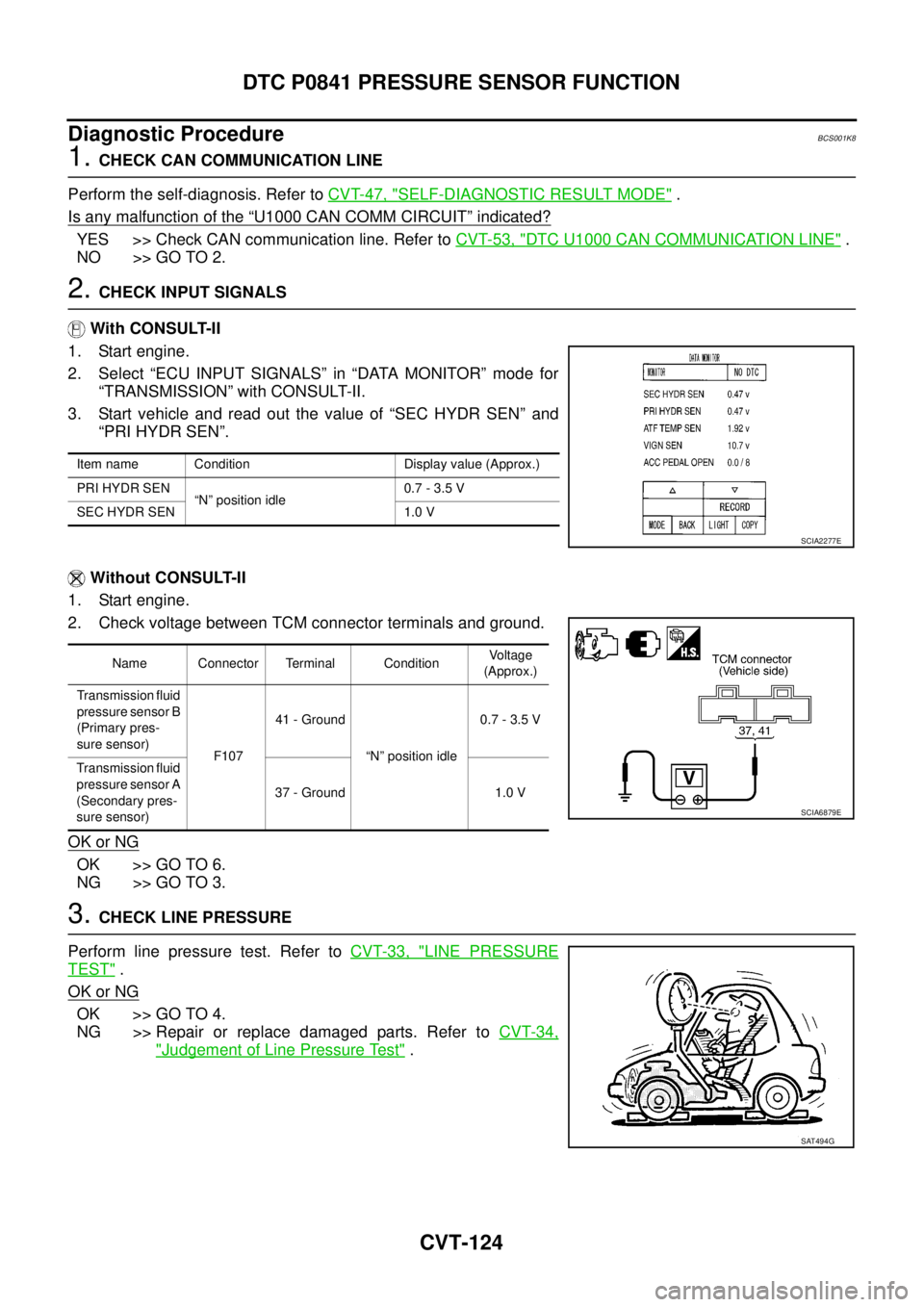
2. Select “ECU INPUT SIGNALS” in “DATA MONITOR” mode for
“TRANSMISSION” with CONSULT-II.
3. Start vehicle and read out the value of “SEC HYDR SEN” and
“PRI HYDR SEN”.
Without CONSULT-II
1. Start engine.
2. Check voltage between TCM connector terminals and ground.
OK or NG
OK >> GO TO 6.
NG >> GO TO 3.
3. CHECK LINE PRESSURE
Perform line pressure test. Refer to CVT-33, "
LINE PRESSURE
TEST" .
OK or NG
OK >> GO TO 4.
NG >> Repair or replace damaged parts. Refer to CVT-34,
"Judgement of Line Pressure Test" .
Item name Condition Display value (Approx.)
PRI HYDR SEN
“N” position idle0.7 - 3.5 V
SEC HYDR SEN 1.0 V
SCIA2277E
Name Connector Terminal ConditionVoltage
(Approx.)
Transmission fluid
pressure sensor B
(Primary pres-
sure sensor)
F10741 - Ground
“N” position idle0.7 - 3.5 V
Transmission fluid
pressure sensor A
(Secondary pres-
sure sensor)37 - Ground 1.0 V
SCIA6879E
SAT494G