Page 1134 of 3502
CVT-128
DTC P0845 TRANSMISSION FLUID PRESSURE SENSOR B CIRCUIT (PRI
PRESSURE SENSOR)
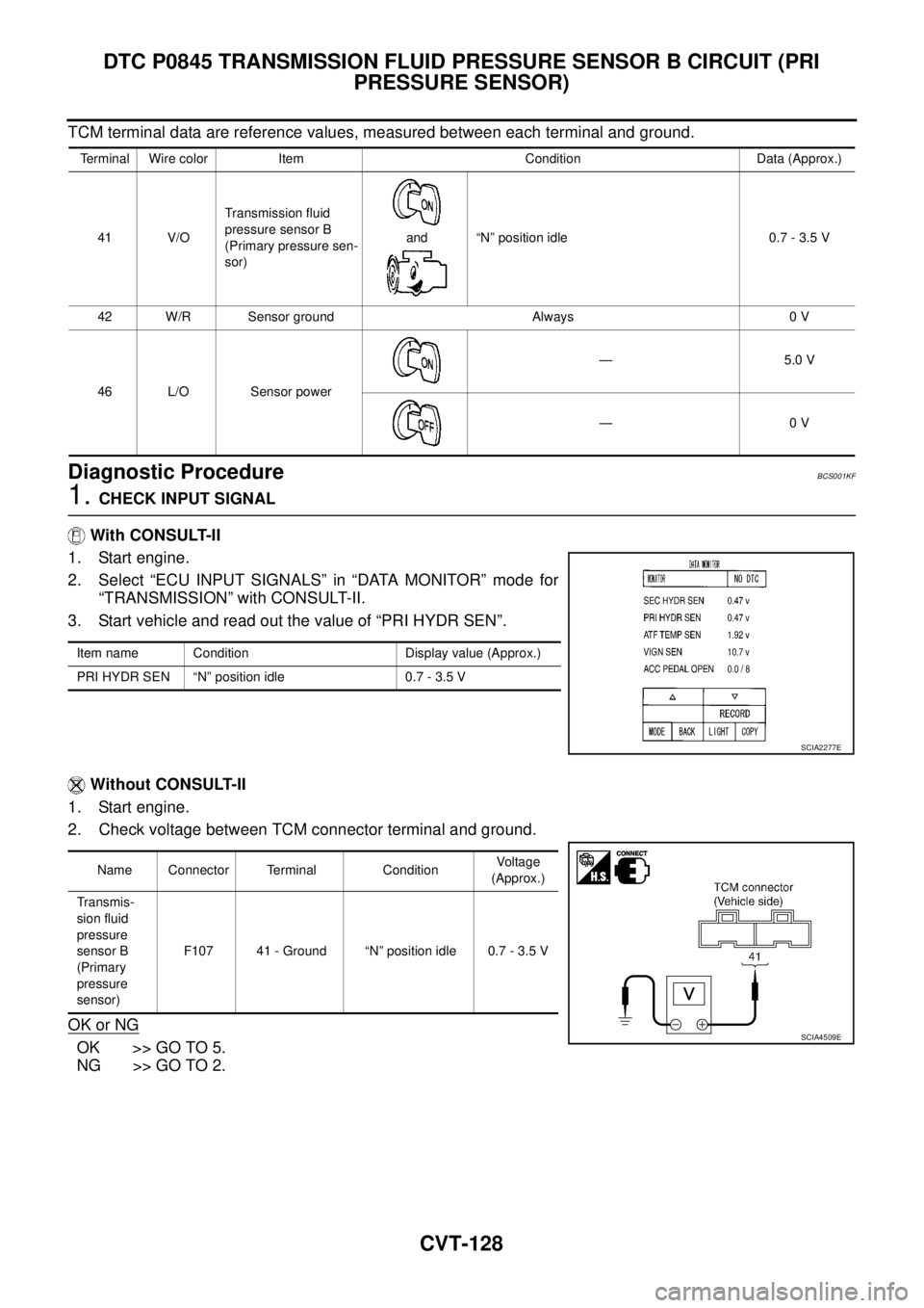
TCM terminal data are reference values, measured between each terminal and ground.
Diagnostic ProcedureBCS001KF
1. CHECK INPUT SIGNAL
With CONSULT-II
1. Start engine.
2. Select “ECU INPUT SIGNALS” in “DATA MONITOR” mode for
“TRANSMISSION” with CONSULT-II.
3. Start vehicle and read out the value of “PRI HYDR SEN”.
Without CONSULT-II
1. Start engine.
2. Check voltage between TCM connector terminal and ground.
OK or NG
OK >> GO TO 5.
NG >> GO TO 2.
Terminal Wire color Item Condition Data (Approx.)
41 V/OTransmission fluid
pressure sensor B
(Primary pressure sen-
sor)and “N” position idle 0.7 - 3.5 V
42 W/R Sensor ground Always 0 V
46 L/O Sensor power— 5.0 V
—0 V
Item name Condition Display value (Approx.)
PRI HYDR SEN “N” position idle 0.7 - 3.5 V
SCIA2277E
Name Connector Terminal ConditionVoltage
(Approx.)
Transmis-
sion fluid
pressure
sensor B
(Primary
pressure
sensor)F107 41 - Ground “N” position idle 0.7 - 3.5 V
SCIA4509E
Page 1135 of 3502
DTC P0845 TRANSMISSION FLUID PRESSURE SENSOR B CIRCUIT (PRI
PRESSURE SENSOR)
CVT-129
D
E
F
G
H
I
J
K
L
MA
B
CVT
2. CHECK SENSOR POWER AND SENSOR GROUND
1. Turn ignition switch ON. (Do not start engine.)
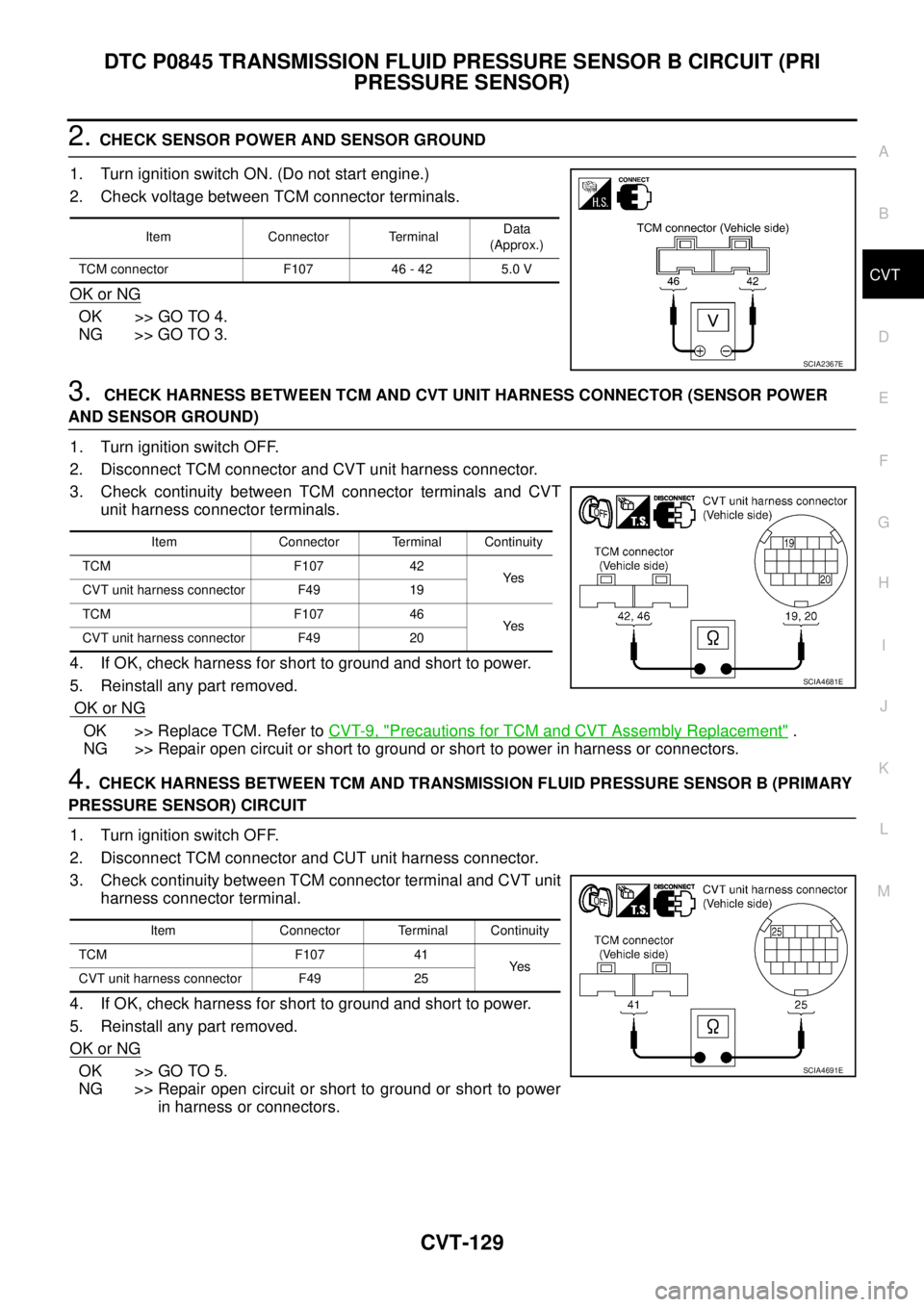
2. Check voltage between TCM connector terminals.
OK or NG
OK >> GO TO 4.
NG >> GO TO 3.
3. CHECK HARNESS BETWEEN TCM AND CVT UNIT HARNESS CONNECTOR (SENSOR POWER
AND SENSOR GROUND)
1. Turn ignition switch OFF.
2. Disconnect TCM connector and CVT unit harness connector.
3. Check continuity between TCM connector terminals and CVT
unit harness connector terminals.
4. If OK, check harness for short to ground and short to power.
5. Reinstall any part removed.
OK or NG
OK >> Replace TCM. Refer to CVT-9, "Precautions for TCM and CVT Assembly Replacement" .
NG >> Repair open circuit or short to ground or short to power in harness or connectors.
4. CHECK HARNESS BETWEEN TCM AND TRANSMISSION FLUID PRESSURE SENSOR B (PRIMARY
PRESSURE SENSOR) CIRCUIT
1. Turn ignition switch OFF.
2. Disconnect TCM connector and CUT unit harness connector.
3. Check continuity between TCM connector terminal and CVT unit
harness connector terminal.
4. If OK, check harness for short to ground and short to power.
5. Reinstall any part removed.
OK or NG
OK >> GO TO 5.
NG >> Repair open circuit or short to ground or short to power
in harness or connectors.
Item Connector TerminalData
(Approx.)
TCM connector F107 46 - 42 5.0 V
SCIA2367E
Item Connector Terminal Continuity
TCM F107 42
Ye s
CVT unit harness connector F49 19
TCM F107 46
Ye s
CVT unit harness connector F49 20
SCIA4681E
Item Connector Terminal Continuity
TCM F107 41
Ye s
CVT unit harness connector F49 25
SCIA4691E
Page 1138 of 3502
CVT-132
DTC P0868 SECONDARY PRESSURE DOWN
Diagnostic ProcedureBCS001KL
1. CHECK INPUT SIGNAL
With CONSULT-II
1. Start engine.
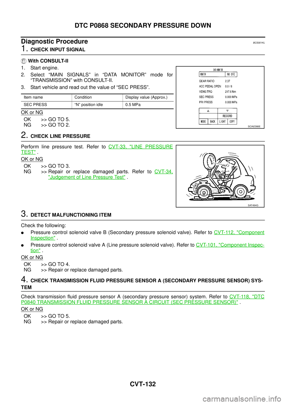
2. Select “MAIN SIGNALS” in “DATA MONITOR” mode for
“TRANSMISSION” with CONSULT-II.
3. Start vehicle and read out the value of “SEC PRESS”.
OK or NG
OK >> GO TO 5.
NG >> GO TO 2.
2. CHECK LINE PRESSURE
Perform line pressure test. Refer to CVT-33, "
LINE PRESSURE
TEST" .
OK or NG
OK >> GO TO 3.
NG >> Repair or replace damaged parts. Refer to CVT-34,
"Judgement of Line Pressure Test" .
3. DETECT MALFUNCTIONING ITEM
Check the following:
�Pressure control solenoid valve B (Secondary pressure solenoid valve). Refer to CVT-112, "Component
Inspection" .
�Pressure control solenoid valve A (Line pressure solenoid valve). Refer to CVT-101, "Component Inspec-
tion" .
OK or NG
OK >> GO TO 4.
NG >> Repair or replace damaged parts.
4. CHECK TRANSMISSION FLUID PRESSURE SENSOR A (SECONDARY PRESSURE SENSOR) SYS-
TEM
Check transmission fluid pressure sensor A (secondary pressure sensor) system. Refer to CVT-118, "
DTC
P0840 TRANSMISSION FLUID PRESSURE SENSOR A CIRCUIT (SEC PRESSURE SENSOR)" .
OK or NG
OK >> GO TO 5.
NG >> Repair or replace damaged parts.
Item name Condition Display value (Approx.)
SEC PRESS “N” position idle 0.5 MPa
SCIA2366E
SAT494G
Page 1142 of 3502
CVT-136
DTC P1701 TRANSMISSION CONTROL MODULE (POWER SUPPLY)
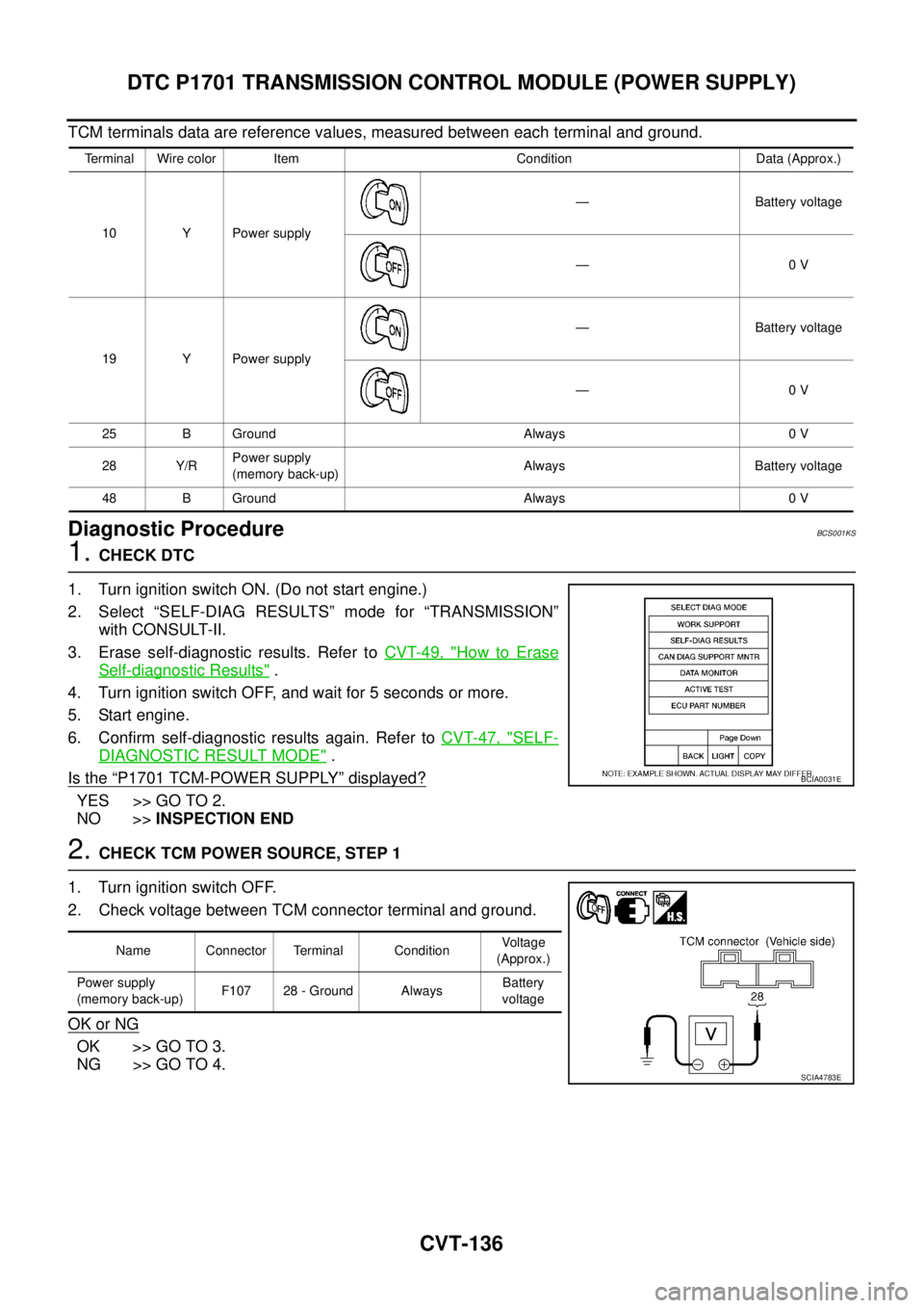
TCM terminals data are reference values, measured between each terminal and ground.
Diagnostic ProcedureBCS001KS
1. CHECK DTC
1. Turn ignition switch ON. (Do not start engine.)
2. Select “SELF-DIAG RESULTS” mode for “TRANSMISSION”
with CONSULT-II.
3. Erase self-diagnostic results. Refer to CVT-49, "
How to Erase
Self-diagnostic Results" .
4. Turn ignition switch OFF, and wait for 5 seconds or more.
5. Start engine.
6. Confirm self-diagnostic results again. Refer to CVT-47, "
SELF-
DIAGNOSTIC RESULT MODE" .
Is the
“P1701 TCM-POWER SUPPLY” displayed?
YES >> GO TO 2.
NO >>INSPECTION END
2. CHECK TCM POWER SOURCE, STEP 1
1. Turn ignition switch OFF.
2. Check voltage between TCM connector terminal and ground.
OK or NG
OK >> GO TO 3.
NG >> GO TO 4.
Terminal Wire color Item Condition Data (Approx.)
10 Y Power supply— Battery voltage
—0 V
19 Y Power supply— Battery voltage
—0 V
25 B Ground Always 0 V
28 Y/RPower supply
(memory back-up)Always Battery voltage
48 B Ground Always 0 V
BCIA0031E
Name Connector Terminal ConditionVoltage
(Approx.)
Power supply
(memory back-up)F107 28 - Ground AlwaysBattery
voltage
SCIA4783E
Page 1143 of 3502
DTC P1701 TRANSMISSION CONTROL MODULE (POWER SUPPLY)
CVT-137
D
E
F
G
H
I
J
K
L
MA
B
CVT
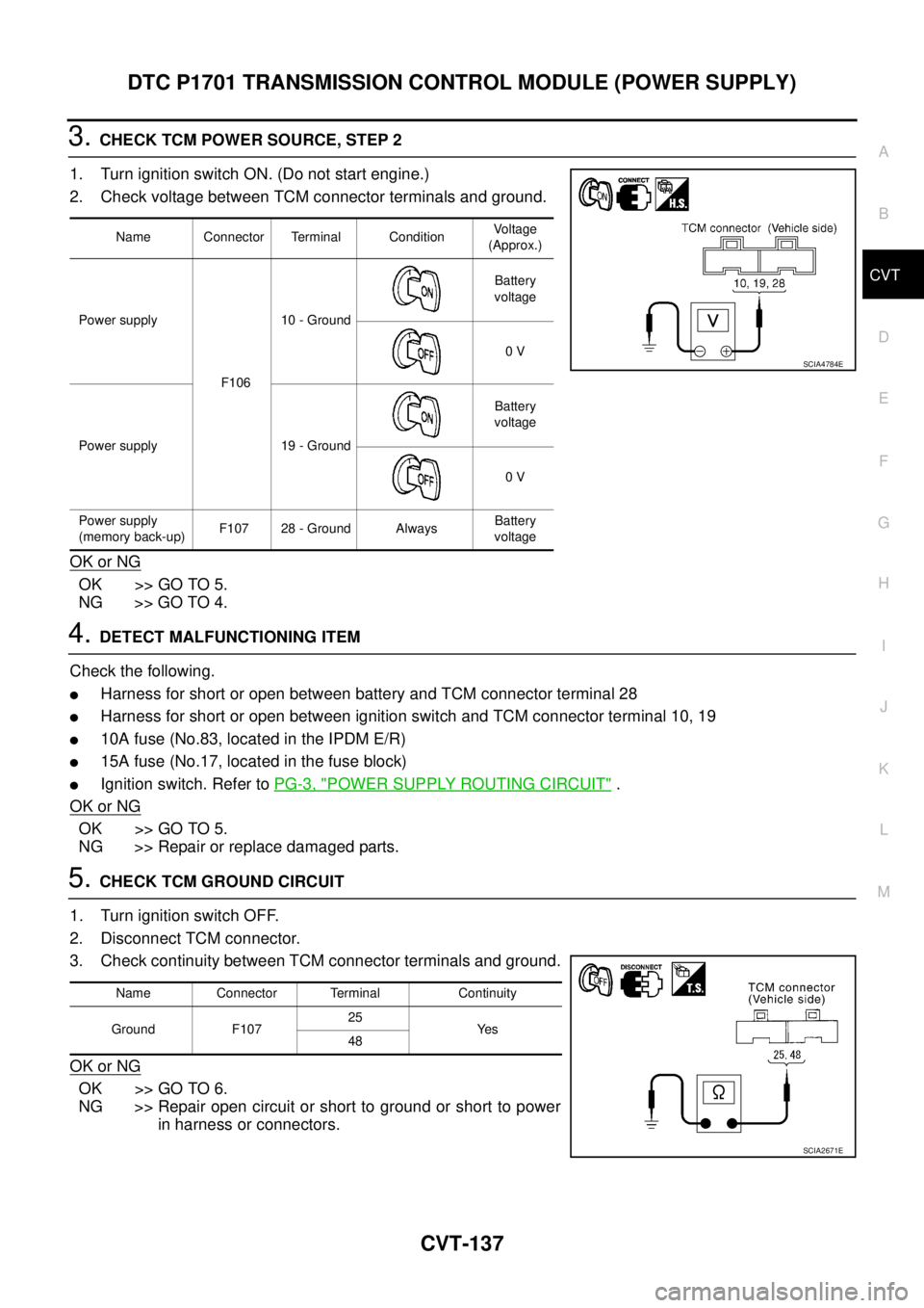
3. CHECK TCM POWER SOURCE, STEP 2
1. Turn ignition switch ON. (Do not start engine.)
2. Check voltage between TCM connector terminals and ground.
OK or NG
OK >> GO TO 5.
NG >> GO TO 4.
4. DETECT MALFUNCTIONING ITEM
Check the following.
�Harness for short or open between battery and TCM connector terminal 28
�Harness for short or open between ignition switch and TCM connector terminal 10, 19
�10A fuse (No.83, located in the IPDM E/R)
�15A fuse (No.17, located in the fuse block)
�Ignition switch. Refer to PG-3, "POWER SUPPLY ROUTING CIRCUIT" .
OK or NG
OK >> GO TO 5.
NG >> Repair or replace damaged parts.
5. CHECK TCM GROUND CIRCUIT
1. Turn ignition switch OFF.
2. Disconnect TCM connector.
3. Check continuity between TCM connector terminals and ground.
OK or NG
OK >> GO TO 6.
NG >> Repair open circuit or short to ground or short to power
in harness or connectors.
Name Connector Terminal ConditionVoltage
(Approx.)
Power supply
F10610 - GroundBattery
voltage
0 V
Power supply 19 - GroundBattery
voltage
0 V
Power supply
(memory back-up)F107 28 - Ground AlwaysBattery
voltage
SCIA4784E
Name Connector Terminal Continuity
Ground F10725
Ye s
48
SCIA2671E
Page 1146 of 3502
CVT-140
DTC P1705 THROTTLE POSITION SENSOR
Diagnostic ProcedureBCS001KY
1. CHECK CAN COMMUNICATION LINE
Perform the self-diagnosis check. Refer to CVT-47, "
SELF-DIAGNOSTIC RESULT MODE" .
Is any malfunction of the
“U1000 CAN COMM CIRCUIT” indicated?
YES >> Check the CAN communication line. Refer to CVT-53, "DTC U1000 CAN COMMUNICATION
LINE" .
NO >> GO TO 2.
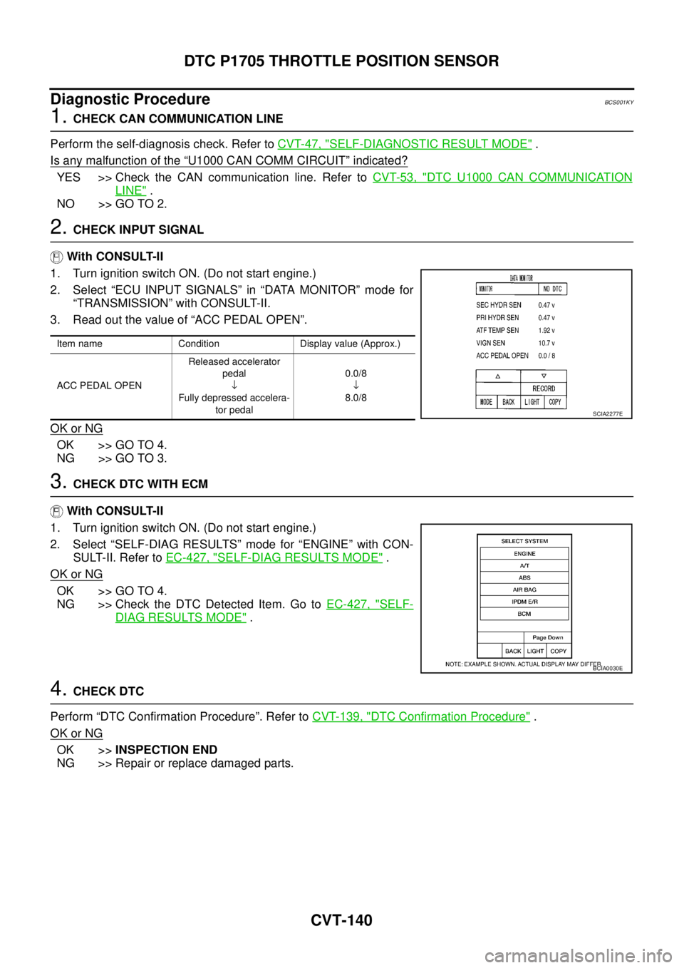
2. CHECK INPUT SIGNAL
With CONSULT-II
1. Turn ignition switch ON. (Do not start engine.)
2. Select “ECU INPUT SIGNALS” in “DATA MONITOR” mode for
“TRANSMISSION” with CONSULT-II.
3. Read out the value of “ACC PEDAL OPEN”.
OK or NG
OK >> GO TO 4.
NG >> GO TO 3.
3. CHECK DTC WITH ECM
With CONSULT-II
1. Turn ignition switch ON. (Do not start engine.)
2. Select “SELF-DIAG RESULTS” mode for “ENGINE” with CON-
SULT-II. Refer to EC-427, "
SELF-DIAG RESULTS MODE" .
OK or NG
OK >> GO TO 4.
NG >> Check the DTC Detected Item. Go to EC-427, "
SELF-
DIAG RESULTS MODE" .
4. CHECK DTC
Perform “DTC Confirmation Procedure”. Refer to CVT-139, "
DTC Confirmation Procedure" .
OK or NG
OK >>INSPECTION END
NG >> Repair or replace damaged parts.
Item name Condition Display value (Approx.)
ACC PEDAL OPENReleased accelerator
pedal
↓
Fully depressed accelera-
tor pedal0.0/8
↓
8.0/8
SCIA2277E
BCIA0030E
Page 1148 of 3502
CVT-142
DTC P1722 ESTM VEHICLE SPEED SIGNAL
Diagnostic ProcedureBCS001L4
1. CHECK CAN COMMUNICATION LINE
Perform the self-diagnosis check. Refer to CVT-47, "
SELF-DIAGNOSTIC RESULT MODE" .
Is any malfunction of the
“U1000 CAN COMM CIRCUIT” indicated?
YES >> Check CAN communication line. Refer to CVT-53, "DTC U1000 CAN COMMUNICATION LINE" .
NO >> GO TO 2.
2. CHECK ABS ACTUATOR AND ELECTRIC UNIT (CONTROL UNIT)
Perform ABS actuator and electric unit (control unit) self-diagnosis check. Refer to BRC-17, "
Self-Diagnosis" .
OK or NG
OK >> GO TO 3.
NG >> Repair or replace damaged parts.
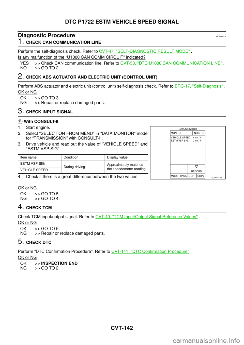
3. CHECK INPUT SIGNAL
With CONSULT-II
1. Start engine.
2. Select “SELECTION FROM MENU” in “DATA MONITOR” mode
for “TRANSMISSION” with CONSULT-II.
3. Drive vehicle and read out the value of “VEHICLE SPEED” and
“ESTM VSP SIG”.
4. Check if there is a great difference between the two values.
OK or NG
OK >> GO TO 5.
NG >> GO TO 4.
4. CHECK TCM
Check TCM input/output signal. Refer to CVT-40, "
TCM Input/Output Signal Reference Values" .
OK or NG
OK >> GO TO 5.
NG >> Repair or replace damaged parts.
5. CHECK DTC
Perform “DTC Confirmation Procedure”. Refer to CVT-141, "
DTC Confirmation Procedure" .
OK or NG
OK >>INSPECTION END
NG >> GO TO 2.
Item name Condition Display value
ESTM VSP SIG
During drivingApproximately matches
the speedometer reading
VEHICLE SPEED
SCIA4510E
Page 1150 of 3502
CVT-144
DTC P1723 CVT SPEED SENSOR FUNCTION
Diagnostic ProcedureBCS001L9
1. CHECK STEP MOTOR FUNCTION
Perform the self-diagnosis check. Refer to CVT-47, "
SELF-DIAGNOSTIC RESULT MODE" .
Is a malfunction in the step motor function indicated in the results?
YES >> Repair or replace damaged parts. (Check the step motor function. Refer to CVT-157, "DTC P1778
STEP MOTOR - FUNCTION" .)
NO >> GO TO 2.
2. CHECK OUTPUT SPEED SENSOR (SECONDARY SPEED SENSOR SYSTEM) AND INPUT SPEED
SENSOR (PRIMARY SPEED SENSOR) SYSTEM
Check secondary speed sensor system and primary speed sensor system. Refer to CVT-79, "
DTC P0720
VEHICLE SPEED SENSOR CVT (SECONDARY SPEED SENSOR)" , CVT-74, "DTC P0715 INPUT SPEED
SENSOR CIRCUIT (PRI SPEED SENSOR)" .
OK or NG
OK >> GO TO 3.
NG >> Repair or replace damaged parts.
3. CHECK ENGINE SPEED SIGNAL SYSTEM
Check engine speed signal system. Refer to CVT-85, "
DTC P0725 ENGINE SPEED SIGNAL" .
OK or NG
OK >> GO TO 4.
NG >> Repair or replace damaged parts. Refer to EC-735, "
IGNITION SIGNAL" .
4. DETECT MALFUNCTIONING ITEM
Check the following:
�Power supply and ground circuit for TCM. Refer to CVT-134, "DTC P1701 TRANSMISSION CONTROL
MODULE (POWER SUPPLY)" .
�The TCM pin terminals for damage or loose connection with harness connector.
OK or NG
OK >> GO TO 5.
NG >> Repair or replace damaged parts.
5. CHECK DTC
Perform “DTC Confirmation Procedure”. Refer to CVT-143, "
DTC Confirmation Procedure" .
OK or NG
OK >>INSPECTION END
NG >> Replace TCM or transaxle assembly. Refer to CVT-9, "
Precautions for TCM and CVT Assembly
Replacement" , CVT-193, "Removal and Installation" .