Page 29 of 3502
A/T CONTROL SYSTEM
AT-21
D
E
F
G
H
I
J
K
L
MA
B
AT
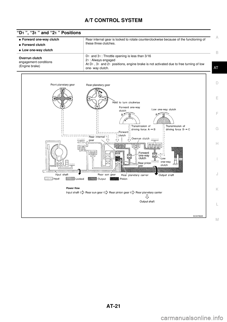
“D1 ”, “31 ” and “21 ” Positions
�Forward one-way clutch
�Forward clutch
�Low one-way clutchRear internal gear is locked to rotate counterclockwise because of the functioning of
these three clutches.
Overrun clutch
engagement conditions
(Engine brake)D
1 and 31 : Throttle opening is less than 3/16
2
1 : Always engaged
At D
1 , 31 and 21 positions, engine brake is not activated due to free turning of low
one- way clutch.
SCIA7864E
Page 251 of 3502

TRANSAXLE ASSEMBLY
AT-243
D
E
F
G
H
I
J
K
L
MA
B
AT
4. Turn crankshaft, and remove four tightening bolts for drive plate
and torque converter.
CAUTION:
Crankshaft should be rotated clockwise, viewed from front
of engine.
5. Remove four bolts in figure.
6. Remove air breather hose. Refer to AT- 2 3 6 , "
AIR BREATHER
HOSE" .
7. Remove transaxle assembly and engine assembly together
from vehicle. Refer to EM-223, "
Removal and Installation" .
8. Remove front suspension member from transaxle assembly and
engine assembly. Refer to FSU-17, "
FRONT SUSPENSION
MEMBER" .
9. Remove drive shaft. Refer to FA X - 8 , "
FRONT DRIVE SHAFT" .
10. Remove front engine mounting bracket (front). Refer to EM-223,
"Removal and Installation" .
11. Remove rear engine mounting bracket (rear). Refer to EM-223, "
Removal and Installation" .
12. Remove A/T fluid level gauge.
13. Remove A/T fluid charging pipe.
14. Disconnect harness connector and wire harness.
15. Remove crankshaft position sensor (POS), from engine assembly. Refer to EM-145, "
Removal and Instal-
lation" .
CAUTION:
�Do not subject it to impact by dropping or hitting it.
�Do not disassemble.
�Do not allow metal filings, etc., to get on sensor's front edge magnetic area.
�Do not place in an area affected by magnetism.
16. Remove starter motor. Refer to SC-18, "
Removal and Installation" .
17. Remove engine mounting insulator (LH) and stopper. Refer to EM-223, "
Removal and Installation" .
18. Remove transaxle assembly fixing bolts with power tool.
19. Remove transaxle assembly from engine assembly.
CAUTION:
Secure torque converter to prevent it from dropping.
SCIA3138E
SCIA3139E
SCIA3143E
Page 253 of 3502

TRANSAXLE ASSEMBLY
AT-245
D
E
F
G
H
I
J
K
L
MA
B
AT
�Align the positions of tightening bolts for drive plate with those of
torque converter, and temporarily tighten bolts. Then, tighten
bolts with the specified torque.
CAUTION:
�When turning crankshaft, turn it clockwise as viewed from
front of engine.
�When tightening the tighten bolts for the torque converter
after fixing crankshaft pulley bolts, be sure to confirm the
tightening torque of crankshaft pulley mounting bolts.
Refer to EM-53, "
TIMING CHAIN" (QR engine), EM-173, "TIMING CHAIN" (VQ engine).
� After converter is installed to drive plate, rotate crankshaft several turns and make sure that tran-
saxle rotates freely without binding.
�Install POS sensor. Refer to EM-145, "Removal and Installation" .
�After completing installation, check for A/T fluid leakage, A/T fluid level, and positions of A/T. Refer to AT-
14, "Checking A/T Fluid" , AT- 2 1 5 , "Adjustment of A/T Position" , AT- 2 1 5 , "Checking of A/T Position" . : 52 N·m (5.3 kg-m, 38 ft-lb)
SCIA3138E
Page 263 of 3502
DISASSEMBLY
AT-255
D
E
F
G
H
I
J
K
L
MA
B
AT
DISASSEMBLYPFP:31020
DisassemblyBCS001OI
1. Drain ATF through drain plug.
2. Remove drain plug gasket from drain plug.
3. Remove torque converter.
4. Check torque converter one-way clutch using check tool as
shown in the figure.
a. Insert check tool into groove of bearing support built into one-
way clutch outer race.
b. When fixing bearing support with check tool, rotate one- way
clutch spline using screwdriver.
c. Check that inner race rotates clockwise only. If not, replace
torque converter assembly.
SCIA0003E
SAT008D
SAT009D
Page 274 of 3502
AT-266
DISASSEMBLY
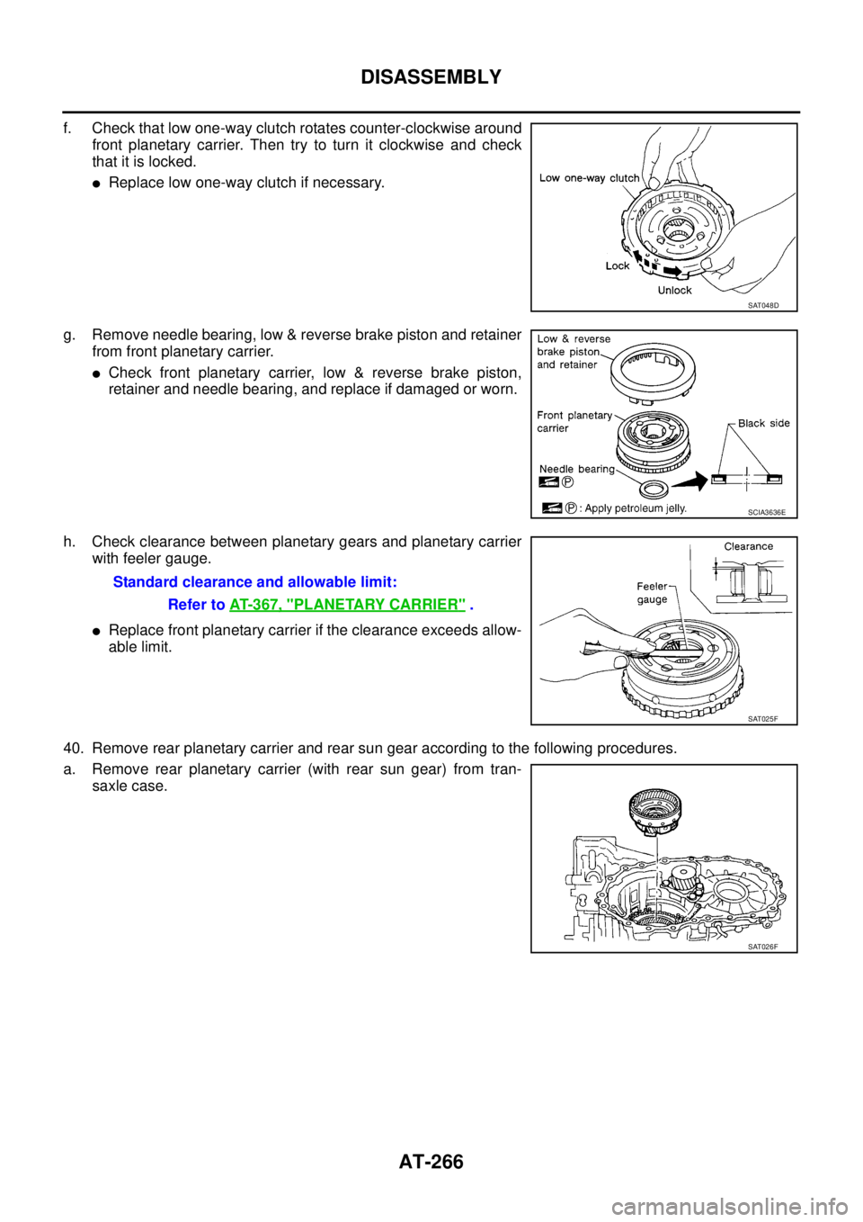
f. Check that low one-way clutch rotates counter-clockwise around
front planetary carrier. Then try to turn it clockwise and check
that it is locked.
�Replace low one-way clutch if necessary.
g. Remove needle bearing, low & reverse brake piston and retainer
from front planetary carrier.
�Check front planetary carrier, low & reverse brake piston,
retainer and needle bearing, and replace if damaged or worn.
h. Check clearance between planetary gears and planetary carrier
with feeler gauge.
�Replace front planetary carrier if the clearance exceeds allow-
able limit.
40. Remove rear planetary carrier and rear sun gear according to the following procedures.
a. Remove rear planetary carrier (with rear sun gear) from tran-
saxle case.
SAT048D
SCIA3636E
Standard clearance and allowable limit:
Refer to AT- 3 6 7 , "
PLANETARY CARRIER" .
SAT025F
SAT026F
Page 391 of 3502
. All hoses must include positive shut-")
PRECAUTIONS
ATC-13
C
D
E
F
G
H
I
K
L
MA
B
AT C
SERVICE HOSES
Be certain that the service hoses display the markings described
(colored hose with black stripe). All hoses must include positive shut-
off devices (either manual or automatic) near the end of the hoses
opposite the manifold gauge.
SERVICE COUPLERS
Never attempt to connect HFC-134a (R-134a) service couplers to a
CFC-12 (R-12) A/C system. The HFC-134a (R-134a) couplers will
not properly connect to the CFC-12 (R-12) system. However, if an
improper connection is attempted, discharging and contamination
may occur.
REFRIGERANT WEIGHT SCALE
Verify that no refrigerant other than HFC-134a (R-134a) and speci-
fied lubricants have been used with the scale. If the scale controls
refrigerant flow electronically, the hose fitting must be 1/2
″ -16
ACME.
CALIBRATING ACR4 WEIGHT SCALE
Calibrate the scale every three months.
To calibrate the weight scale on the ACR4:
1. Press Shift/Reset and Enter at the same time.
2. Press 8787 . “A1 ” will be displayed.
3. Remove all weight from the scale.
4. Press 0 , then press Enter . “0.00 ” will be displayed and change to “A2 ”.
5. Place a known weight (dumbbell or similar weight), between 4.5 and 8.6 kg (10 and 19 lb.) on the center
of the weight scale.
6. Enter the known weight using four digits. (Example 10 lb. = 10.00, 10.5 lb. = 10.50)
7. Press Enter — the display returns to the vacuum mode.
8. Press Shift/Reset and Enter at the same time.
9. Press 6 — the known weight on the scale is displayed.
10. Remove the known weight from the scale. “0.00 ” will be displayed.
11 . P r e s s Shift/Reset to return the ACR4 to the program mode.
RHA272D
Shut-off valve rotation A/C service valve
Clockwise Open
Counterclockwise Close
RHA273D
RHA274D
Page 528 of 3502
ATC-150
SERVICE DATA AND SPECIFICATIONS (SDS)
SERVICE DATA AND SPECIFICATIONS (SDS)PFP:00030
CompressorBJS000I4
LubricantBJS000I5
RefrigerantBJS000I6
Engine Idling SpeedBJS000I7
Refer to EC-45, "Idle Speed and Ignition Timing Check" (QR engine) or EC-387, "Idle Speed and Ignition Tim-
ing Check" (VQ engine).
Belt TensionBJS000I8
Refer to EM-14, "DRIVE BELTS" (QR engine) or EM-128, "DRIVE BELTS" (VQ engine).
ModelZEXEL VALEO CLIMATE CONTROL make
DKS-17D
Ty p eSwash plate
Displacement
cm
3 (cu in)/rev175 (10.7)
Cylinder bore × stroke
mm (in)30.5 (1.20) × 24.0 (0.94)
Direction of rotationClockwise (viewed from drive end)
Drive beltPoly V
ModelZEXEL VALEO CLIMATE CONTROL make
DKS-17D
NameNissan A/C System Oil Type S (DH-PS)
Capacity
m (lmp fl oz)Total in system 150 (5.3)
Compressor (Service part) charg-
ing amount150 (5.3)
Ty p eHFC-134a (R-134a)
Capacity
kg (lb)0.5 (1.1)
Page 583 of 3502
INTEGRATED DISPLAY SYSTEM
AV-55
C
D
E
F
G
H
I
J
L
MA
B
AV
On Board Self-Diagnosis FunctionBKS00228
DESCRIPTION
When performing self-diagnosis mode, the following menu is displayed.
DIAGNOSIS ITEM
Self-Diagnosis ModeBKS00229
OPERATION PROCEDURES
1. Start the engine.
2. Turn the audio system OFF.
3. While pressing the “MUTE” button, turn the volume control dial
clockwise or counterclockwise for 30 clicks or more. (When the
self-diagnosis mode is started, a short beep will be heard.)
4. Initial diagnosis screen is displayed.
�Perform diagnosis according to the audio preset No. “1, 2, 3,
4”.
FULL BLINK
All display unit segments turn ON.
Diagnosis itemFunction
switchDescription
FULL BLINK 1 All display unit segments turn ON.
HVAC DIAG 2 Self-diagnosis of air conditioner system is performed.
VERSION 3 Software version of each unit is displayed.
DIAG END 4 Exit from self-diagnosis mode and return to normal screen.
SKIB0828E
SKIA7023J
SKIA7024J


SERVICE DATA AND SPECIFICATIONS (SDS)PFP:00030
CompressorBJS000I4
LubricantBJS000I5
RefrigerantBJS000I6
Engine Idling SpeedBJS000I7
Refer to EC-45, \"Idl")
