Page 1044 of 3502
CVT-38
TROUBLE DIAGNOSIS
4. CHECK “N” POSITION FUNCTION
1. Start engine.
2. Move selector lever to “N” position.
3. Release parking brake.
Does vehicle move forward or backward?
YES >> Mark the box CVT-166, "In “N” Position, Vehicle Moves" on the CVT-27, "DIAGNOSTIC WORK-
SHEET" . Continue “Road Test”.
NO >> GO TO 5.
5. CHECK SHIFT SHOCK
1. Apply foot brake.
2. Move selector lever to “R” position.
Is there large shock when changing from
“N” to “R” position?
YES >> Mark the box CVT-167, "Large Shock “N” → “R” Position" on the CVT-27, "DIAGNOSTIC WORK-
SHEET" . Continue “Road Test”.
NO >> GO TO 6.
6. CHECK “R” POSITION FUNCTION
Release foot brake for several seconds.
Does vehicle creep backward when foot brake is released?
YES >> GO TO 7.
NO >> Mark the box CVT-168, "
Vehicle Does Not Creep Backward in “R” Position" on the CVT-27,
"DIAGNOSTIC WORKSHEET" . Continue “Road Test”.
7. CHECK “D” POSITION FUNCTION
Move selector lever to “D” position and check if vehicle creeps forward.
Does vehicle creep forward in
“D” position?
YES >> Go to CVT-38, "Cruise Test" .
NO >> Mark the box CVT-169, "
Vehicle Does Not Creep Forward in “D” Position" on the CVT-27, "DIAG-
NOSTIC WORKSHEET" . Continue “Road Test”.
Cruise TestBCS001GN
1. CHECK VEHICLE SPEED WHEN SHIFTING GEARS — PART 1
1. Drive vehicle for approximately 10 minutes to warm engine oil and CVT fluid up to operating temperature.
2. Park vehicle on flat surface.
3. Move selector lever to “P” position.
4. Start engine.
5. Move selector lever to “D” position.
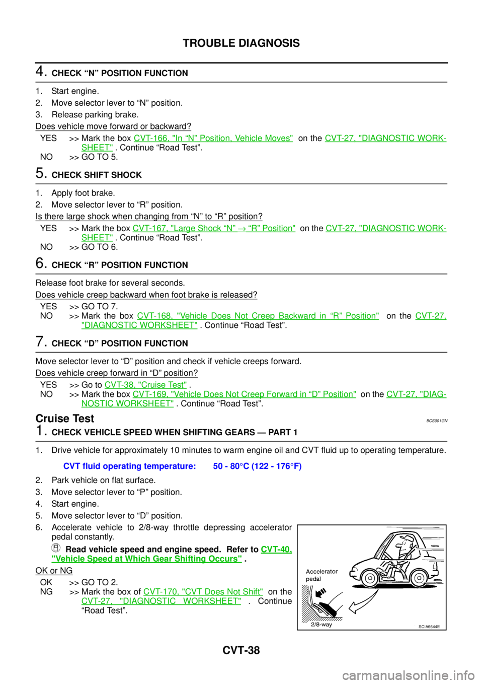
6. Accelerate vehicle to 2/8-way throttle depressing accelerator
pedal constantly.
Read vehicle speed and engine speed. Refer to CVT-40,
"Vehicle Speed at Which Gear Shifting Occurs" .
OK or NG
OK >> GO TO 2.
NG >> Mark the box of CVT-170, "
CVT Does Not Shift" on the
CVT-27, "
DIAGNOSTIC WORKSHEET" . Continue
“Road Test”. CVT fluid operating temperature: 50 - 80°C (122 - 176°F)
SCIA6644E
Page 1045 of 3502
TROUBLE DIAGNOSIS
CVT-39
D
E
F
G
H
I
J
K
L
MA
B
CVT
2. CHECK VEHICLE SPEED WHEN SHIFTING GEARS — PART 2
1. Park vehicle on flat surface.
2. Move selector lever to “D” position.
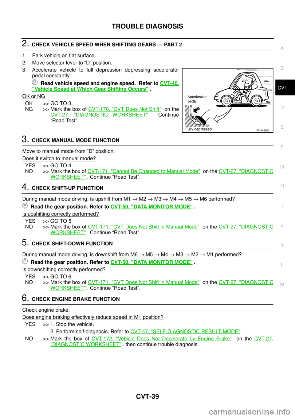
3. Accelerate vehicle to full depression depressing accelerator
pedal constantly.
Read vehicle speed and engine speed. Refer to CVT-40,
"Vehicle Speed at Which Gear Shifting Occurs" .
OK or NG
OK >> GO TO 3.
NG >> Mark the box of CVT-170, "
CVT Does Not Shift" on the
CVT-27, "
DIAGNOSTIC WORKSHEET" . Continue
“Road Test”.
3. CHECK MANUAL MODE FUNCTION
Move to manual mode from “D” position.
Does it switch to manual mode?
YES >> GO TO 4.
NO >> Mark the box of CVT-171, "
Cannot Be Changed to Manual Mode" on the CVT-27, "DIAGNOSTIC
WORKSHEET" . Continue “Road Test”.
4. CHECK SHIFT-UP FUNCTION
During manual mode driving, is upshift from M1 → M2 → M3 → M4 → M5 → M6 performed?
Read the gear position. Refer to CVT-50, "
DATA MONITOR MODE" .
Is upshifting correctly performed?
YES >> GO TO 5.
NO >> Mark the box of CVT-171, "
CVT Does Not Shift in Manual Mode" on the CVT-27, "DIAGNOSTIC
WORKSHEET" . Continue “Road Test”.
5. CHECK SHIFT-DOWN FUNCTION
During manual mode driving, is downshift from M6 → M5 → M4 → M3 → M2 → M1 performed?
Read the gear position. Refer to CVT-50, "
DATA MONITOR MODE" .
Is downshifting correctly performed?
YES >> GO TO 6.
NO >> Mark the box of CVT-171, "
CVT Does Not Shift in Manual Mode" on the CVT-27, "DIAGNOSTIC
WORKSHEET" . Continue “Road Test”.
6. CHECK ENGINE BRAKE FUNCTION
Check engine brake.
Does engine braking effectively reduce speed in M1 position?
YES >> 1. Stop the vehicle.
2. Perform self-diagnosis. Refer to CVT-47, "
SELF-DIAGNOSTIC RESULT MODE" .
NO >> Mark the box of CVT-172, "
Vehicle Does Not Decelerate by Engine Brake" on the CVT-27,
"DIAGNOSTIC WORKSHEET" . then continue trouble diagnosis.
SCIA4366E
Page 1051 of 3502
TROUBLE DIAGNOSIS
CVT-45
D
E
F
G
H
I
J
K
L
MA
B
CVT
CONSULT-II SETTING PROCEDURE
Refer to GI-34, "CONSULT-II Start Procedure" .
WORK SUPPORT MODE
Display Item List
Engine Brake Adjustment
1. Touch “WORK SUPPORT” on “SELECT DIAG MODE” screen.
2. Touch “ENGINE BRAKE ADJ.”.
3. Touch “START”.
RANGESelector lever in “N” or “P” position N·P
Selector lever in “R” position R
Selector lever in “D” position D
M GEAR POS During driving 1, 2, 3, 4, 5, 6 Item name Condition Display value (Approx.)
Item name Description
ENGINE BRAKE ADJ. The engine brake level setting can be canceled.
CONFORM CVTF DETERIORTN The CVT fluid deterioration level can be checked.
BCIA0031E
SCIA4287E
SCIA4288E
Page 1052 of 3502
CVT-46
TROUBLE DIAGNOSIS
4. Set “ENGINE BRAKE LEVEL” by touching “UP” or “DOWN”.
5. Turn ignition switch OFF, wait at least 5 seconds and then turn
ignition switch ON.
6. Engine brake level set is completed.
CAUTION:
Mode of “+1” “0” “-1” “-2” “OFF” can be selected by press-
ing the “UP” “DOWN” on CONSULT-II screen. However, do not select mode other than “0” and
“OFF”. If the “+1” or “-1” or “-2” is selected, that might cause the irregular driveability.
Check CVT Fluid Deterioration Date
1. Touch “WORK SUPPORT” on “SELECT DIAG MODE” screen.
2. Touch “CONFORM CVTF DETERIORTN”.
3. Check “CVTF DETERIORATION DATE”“ENGINE BRAKE LEVEL”
0: Initial set value (Engine brake level control is
activated)
OFF: Engine brake level control is deactivated.
SAT934J
BCIA0031E
SCIA4287E
“CVTF DETERIORATION DATE”
More than 210000:
It is necessary to change CVT fluid.
Less than 210000:
It is not necessary to change CVT fluid.
SCIA4289E
Page 1053 of 3502
TROUBLE DIAGNOSIS
CVT-47
D
E
F
G
H
I
J
K
L
MA
B
CVT
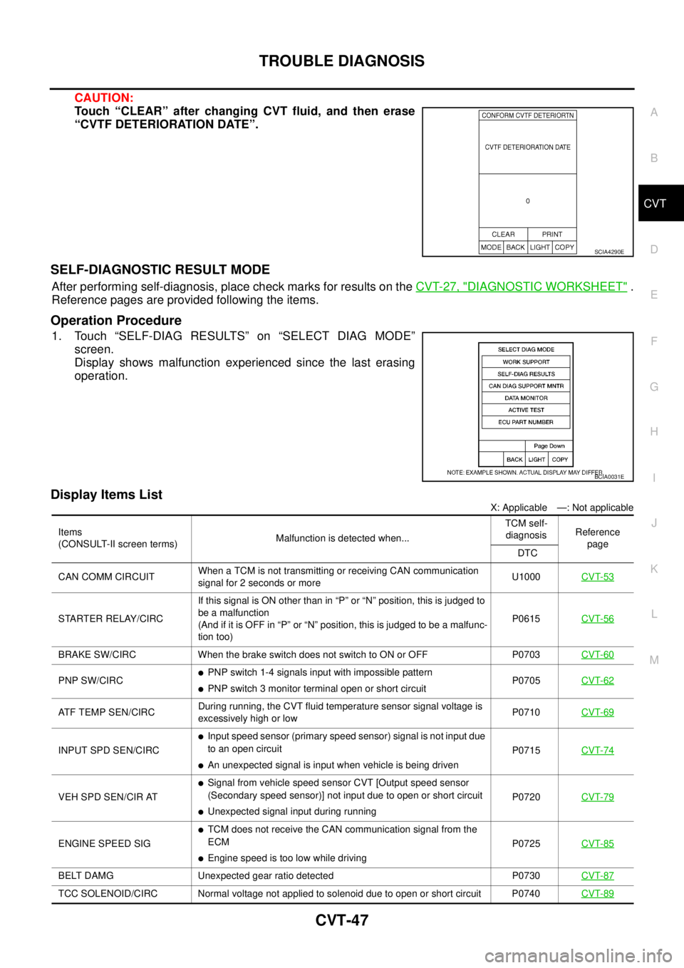
CAUTION:
Touch “CLEAR” after changing CVT fluid, and then erase
“CVTF DETERIORATION DATE”.
SELF-DIAGNOSTIC RESULT MODE
After performing self-diagnosis, place check marks for results on the CVT-27, "DIAGNOSTIC WORKSHEET" .
Reference pages are provided following the items.
Operation Procedure
1. Touch “SELF-DIAG RESULTS” on “SELECT DIAG MODE”
screen.
Display shows malfunction experienced since the last erasing
operation.
Display Items List
X: Applicable —: Not applicable
SCIA4290E
BCIA0031E
Items
(CONSULT-II screen terms)Malfunction is detected when...TCM self-
diagnosisReference
page
DTC
CAN COMM CIRCUITWhen a TCM is not transmitting or receiving CAN communication
signal for 2 seconds or moreU1000CVT-53
STARTER RELAY/CIRCIf this signal is ON other than in “P” or “N” position, this is judged to
be a malfunction
(And if it is OFF in “P” or “N” position, this is judged to be a malfunc-
tion too)P0615CVT-56
BRAKE SW/CIRC When the brake switch does not switch to ON or OFF P0703CVT-60
PNP SW/CIRC�PNP switch 1-4 signals input with impossible pattern
�PNP switch 3 monitor terminal open or short circuitP0705CVT-62
ATF TEMP SEN/CIRCDuring running, the CVT fluid temperature sensor signal voltage is
excessively high or lowP0710CVT-69
INPUT SPD SEN/CIRC
�Input speed sensor (primary speed sensor) signal is not input due
to an open circuit
�An unexpected signal is input when vehicle is being drivenP0715CVT-74
VEH SPD SEN/CIR AT
�Signal from vehicle speed sensor CVT [Output speed sensor
(Secondary speed sensor)] not input due to open or short circuit
�Unexpected signal input during runningP0720CVT-79
ENGINE SPEED SIG
�TCM does not receive the CAN communication signal from the
ECM
�Engine speed is too low while drivingP0725CVT-85
BELT DAMG Unexpected gear ratio detected P0730CVT-87
TCC SOLENOID/CIRC Normal voltage not applied to solenoid due to open or short circuit P0740CVT-89
Page 1061 of 3502
DTC U1000 CAN COMMUNICATION LINE
CVT-55
D
E
F
G
H
I
J
K
L
MA
B
CVT
TCM terminal data are reference values, measured between each terminal and ground.
Diagnostic ProcedureBCS001GX
1. CHECK CAN COMMUNICATION CIRCUIT
With CONSULT-II
1. Turn ignition switch ON and start engine.
2. Select “SELF-DIAG RESULTS” mode for “TRANSMISSION”
with CONSULT-II.
Is any malfunction of the
“U1000 CAN COMM CIRCUIT” indicated?
YES >> Print out CONSULT-II screen, Go to LAN section. Refer
to LAN-49, "
CAN System Specification Chart" .
NO >>INSPECTION END
TerminalWire
colorItem Condition Data (Approx.)
5 L CAN-H — —
6 P CAN-L — —
SCIA5982E
Page 1064 of 3502
CVT-58
DTC P0615 START SIGNAL CIRCUIT
TCM terminal data are reference values, measured between each terminal and ground.
Diagnostic ProcedureBCS001H4
1. CHECK STARTER RELAY
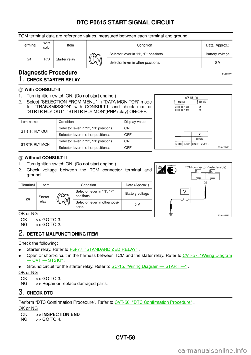
With CONSULT-II
1. Turn ignition switch ON. (Do not start engine.)
2. Select “SELECTION FROM MENU” in “DATA MONITOR” mode
for “TRANSMISSION” with CONSULT-II and check monitor
“STRTR RLY OUT”, “STRTR RLY MON”(PNP relay) ON/OFF.
Without CONSULT-II
1. Turn ignition switch ON. (Do not start engine.)
2. Check voltage between the TCM connector terminal and
ground.
OK or NG
OK >> GO TO 3.
NG >> GO TO 2.
2. DETECT MALFUNCTIONING ITEM
Check the following:
�Starter relay. Refer to PG-77, "STANDARDIZED RELAY" .
�Open or short-circuit in the harness between TCM and the stater relay. Refer to CVT-57, "Wiring Diagram
— CVT — STSIG" .
�Ground circuit for the starter relay. Refer to SC-15, "Wiring Diagram — START —" .
OK or NG
OK >> GO TO 3.
NG >> Repair or replace damaged parts.
3. CHECK DTC
Perform “DTC Confirmation Procedure”. Refer to CVT-56, "
DTC Confirmation Procedure" .
OK or NG
OK >>INSPECTION END
NG >> GO TO 4.
TerminalWire
colorItem Condition Data (Approx.)
24 R/B Starter relaySelector lever in “N”, “P” positions. Battery voltage
Selector lever in other positions. 0 V
Item name Condition Display value
STRTR RLY OUTSelector lever in “P”, “N” positions. ON
Selector lever in other positions. OFF
STRTR RLY MONSelector lever in “P”, “N” positions. ON
Selector lever in other positions. OFF
Terminal Item Condition Data (Approx.)
24Starter
relaySelector lever in “N”, “P”
positions.Battery voltage
Selector lever in other posi-
tions.0 V
SCIA2274E
SCIA2022E
Page 1067 of 3502
DTC P0703 STOP LAMP SWITCH CIRCUIT
CVT-61
D
E
F
G
H
I
J
K
L
MA
B
CVT
Diagnostic ProcedureBCS001HA
1. CHECK CAN COMMUNICATION LINE
Perform the self-diagnosis check. Refer to CVT-47, "
SELF-DIAGNOSTIC RESULT MODE" .
Is any malfunction of the
“U1000 CAN COMM CIRCUIT” indicated?
YES >> Check CAN communication line. Refer to CVT-53, "DTC U1000 CAN COMMUNICATION LINE" .
NO >> GO TO 2.
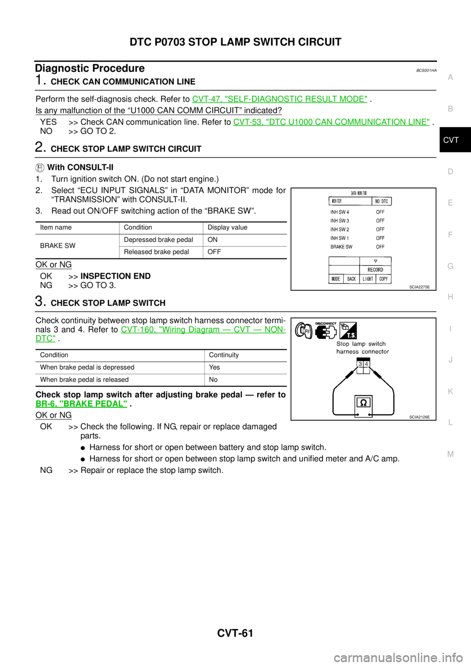
2. CHECK STOP LAMP SWITCH CIRCUIT
With CONSULT-II
1. Turn ignition switch ON. (Do not start engine.)
2. Select “ECU INPUT SIGNALS” in “DATA MONITOR” mode for
“TRANSMISSION” with CONSULT-II.
3. Read out ON/OFF switching action of the “BRAKE SW”.
OK or NG
OK >>INSPECTION END
NG >> GO TO 3.
3. CHECK STOP LAMP SWITCH
Check continuity between stop lamp switch harness connector termi-
nals 3 and 4. Refer to CVT-160, "
Wiring Diagram — CVT — NON-
DTC" .
Check stop lamp switch after adjusting brake pedal — refer to
BR-6, "
BRAKE PEDAL" .
OK or NG
OK >> Check the following. If NG, repair or replace damaged
parts.
�Harness for short or open between battery and stop lamp switch.
�Harness for short or open between stop lamp switch and unified meter and A/C amp.
NG >> Repair or replace the stop lamp switch.
Item name Condition Display value
BRAKE SWDepressed brake pedal ON
Released brake pedal OFF
SCIA2275E
Condition Continuity
When brake pedal is depressed Yes
When brake pedal is released No
SCIA2126E