Page 2334 of 3502
![NISSAN TEANA 2003 Service Manual EM-226
[VQ]
ENGINE ASSEMBLY
6. Remove front suspension member mounting nuts and bolts. Refer to FSU-5, "FRONT SUSPENSION
ASSEMBLY" .
7. Carefully lower engine, transaxle and front suspension member](/manual-img/5/57392/w960_57392-2333.png "NISSAN TEANA 2003 Service Manual EM-226
[VQ]
ENGINE ASSEMBLY
6. Remove front suspension member mounting nuts and bolts. Refer to FSU-5, \"FRONT SUSPENSION
ASSEMBLY\" .
7. Carefully lower engine, transaxle and front suspension member")
EM-226
[VQ]
ENGINE ASSEMBLY
6. Remove front suspension member mounting nuts and bolts. Refer to FSU-5, "FRONT SUSPENSION
ASSEMBLY" .
7. Carefully lower engine, transaxle and front suspension member assembly. When performing work,
observe the following caution.
CAUTION:
�Confirm there is no interference with vehicle.
�Make sure that all connection points have been disconnected.
�Keep in mind the center of vehicle gravity changes. If necessary, use jack(s) to support vehicle
at rear jacking point(s) to prevent it from falling it off the lift.
Separation Work
1. Remove power steering oil pump, power steering piping and power steering bracket from engine and tran-
saxle assembly. Refer to PS-39, "
HYDRAULIC LINE" .
2. Remove starter motor. Refer to SC-14, "
STARTING SYSTEM" .
3. Disconnect harness connector of engine mounting insulators (front and rear).
4. Remove engine mounting (front) and engine mounting (rear) through-bolts.
5. Lift with hoist and separate engine and transaxle assembly from front suspension member.
CAUTION:
Before and during this lifting, always make sure that any harnesses are not connected.
6. Remove each engine mounting insulator and each engine mounting bracket from engine, transaxle and
front suspension member.
7. Separate engine and transaxle. Refer to AT- 2 4 1 , "
TRANSAXLE ASSEMBLY" (A/T), CVT-193, "TRAN-
SAXLE ASSEMBLY" (CVT).
INSTALLATION
Note the following, and install in the reverse order of removal.
�Do not allow engine mounting insulator to be damage and careful no engine oil gets on it.
�For a path with a specified installation orientation, refer to component figure in EM-223, "Removal and
Installation" .
�Make sure all engine mounting insulators are seated properly, then tighten nuts and bolts.
INSPECTION AFTER INSTALLATION
Inspection for Leaks
The following are procedures for checking fluids leak, lubricates leak and exhaust gases leak.
�Before starting engine, check oil/fluid levels including engine coolant and engine oil. If less than required
quantity, fill to the specified level. Refer to MA-14, "
RECOMMENDED FLUIDS AND LUBRICANTS" .
�Use procedure below to check for fuel leakage.
–Turn ignition switch “ON” (with engine stopped). With fuel pressure applied to fuel piping, check for fuel
leakage at connection points.
–Start engine. With engine speed increased, check again for fuel leakage at connection points.
�Run engine to check for unusual noise and vibration.
�Warm up engine thoroughly to make sure there is no leakage of fuel, exhaust gases, or any oil/fluids
including engine oil and engine coolant.
�Bleed air from lines and hoses of applicable lines, such as in cooling system.
�After cooling down engine, again check oil/fluid levels including engine oil and engine coolant. Refill to the
specified level, if necessary.
Page 2335 of 3502
ENGINE ASSEMBLY
EM-227
[VQ]
C
D
E
F
G
H
I
J
K
L
MA
EM
Summary of the inspection items:
* Transmission/transaxle/CVT fluid. power steering fluid, brake fluid, etc.Item Before starting engine Engine running After engine stopped
Engine coolant Level Leakage Level
Engine oil Level Leakage Level
Other oils and fluid* Level Leakage Level
Fuel Leakage Leakage Leakage
Exhaust gases — Leakage —
Page 2337 of 3502
![NISSAN TEANA 2003 Service Manual CYLINDER BLOCK
EM-229
[VQ]
C
D
E
F
G
H
I
J
K
L
MA
EM
DISASSEMBLY
NOTE:
Show VQ35DE (with main bearing beam, connecting rod bearing cap is tighten by bolts) as an example unless
the figure includes s](/manual-img/5/57392/w960_57392-2336.png "NISSAN TEANA 2003 Service Manual CYLINDER BLOCK
EM-229
[VQ]
C
D
E
F
G
H
I
J
K
L
MA
EM
DISASSEMBLY
NOTE:
Show VQ35DE (with main bearing beam, connecting rod bearing cap is tighten by bolts) as an example unless
the figure includes s")
CYLINDER BLOCK
EM-229
[VQ]
C
D
E
F
G
H
I
J
K
L
MA
EM
DISASSEMBLY
NOTE:
Show VQ35DE (with main bearing beam, connecting rod bearing cap is tighten by bolts) as an example unless
the figure includes specification.
1. Remove engine assembly from vehicle, and separate front suspension member and transaxle from
engine. Refer to EM-223, "
ENGINE ASSEMBLY" .
2. Remove exhaust manifolds (right and left banks). Refer to EM-140, "
EXHAUST MANIFOLD AND THREE
WAY CATALYST" .
3. Install engine sub-attachment with engine stand shaft (SST) to
right side of cylinder block.
�Use spacer to engine front side.
4. Lift engine, and mount it onto engine stand (SST).
1. Reinforcement plate 2. Drive plate 3. Rear oil seal retainer
4. Knock sensor 5. Cylinder block 6. Thrust bearing (upper)
7. Main bearing (upper) 8. Crankshaft 9. Key
10. Thrust bearing (lower) 11. Main bearing (lower) 12. Main bearing cap
13. Main bearing cap bolt 14. Main bearing beam 15. Baffle plate
16. Connecting rod nut 17. Connecting rod bolt 18. Connecting rod bearing cap
19. Connecting rod bearing 20. Connecting rod 21. Snap ring
22. Piston pin 23. Piston 24. Oil ring
25. Second ring 26. Top ring 27. Pilot converter
28. Oil jet
PBIC2486E
PBIC2618E
Page 2338 of 3502
![NISSAN TEANA 2003 Service Manual EM-230
[VQ]
CYLINDER BLOCK
�A widely use engine stand can be used.
CAUTION:
Use engine stand that has a load capacity [approximately
220 kg (441 lb) or more] large enough for supporting the
engine w](/manual-img/5/57392/w960_57392-2337.png "NISSAN TEANA 2003 Service Manual EM-230
[VQ]
CYLINDER BLOCK
�A widely use engine stand can be used.
CAUTION:
Use engine stand that has a load capacity [approximately
220 kg (441 lb) or more] large enough for supporting the
engine w")
EM-230
[VQ]
CYLINDER BLOCK
�A widely use engine stand can be used.
CAUTION:
Use engine stand that has a load capacity [approximately
220 kg (441 lb) or more] large enough for supporting the
engine weight.
NOTE:
This example is engine stand for holding at transaxle mount-
ing side with drive plate removed.
5. Drain engine oil. Refer to LU-21, "
Changing Engine Oil" .
6. Drain engine coolant by removing water drain plugs from cylin-
der block both sides at “A” and “D” and cylinder block front side
at “B” as shown in the figure.
NOTE:
Water drain plug at the right bank side for VQ35DE is also used
as a connector of water pipe for oil cooler. Refer to LU-23, "
OIL
COOLER (VQ35DE)" .
7. Remove drive plate. Fix crankshaft pulley with pulley holder [SST: KV10109300], and remove mounting
bolts.
�Loosen mounting bolts in diagonal order.
CAUTION:
�Do not disassemble drive plate.
�Do not place drive plate with signal plate facing down.
�When handling signal plate, take care not to damage or
scratch it.
�Handle signal plate in a manner that prevents it from
becoming magnetized.
8. Remove cylinder head. Refer to EM-210, "
CYLINDER HEAD" .
9. Remove knock sensor.
CAUTION:
Carefully handle sensor avoiding shocks.
PBIC0085E
PBIC2487E
SEM760G
Page 2341 of 3502
CYLINDER BLOCK
EM-233
[VQ]
C
D
E
F
G
H
I
J
K
L
MA
EM
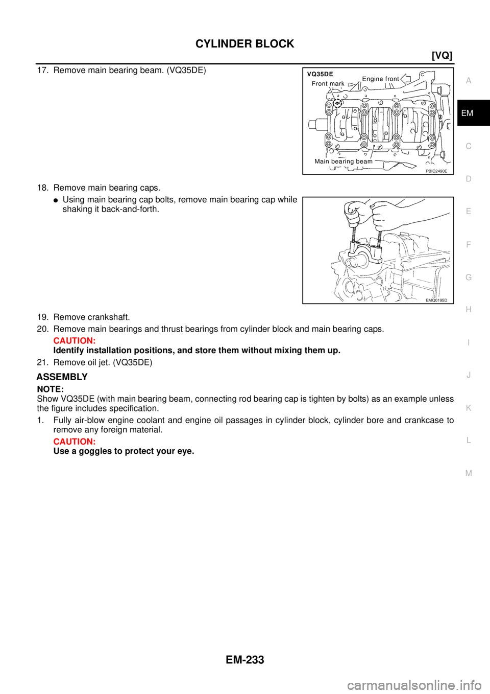
17. Remove main bearing beam. (VQ35DE)
18. Remove main bearing caps.
�Using main bearing cap bolts, remove main bearing cap while
shaking it back-and-forth.
19. Remove crankshaft.
20. Remove main bearings and thrust bearings from cylinder block and main bearing caps.
CAUTION:
Identify installation positions, and store them without mixing them up.
21. Remove oil jet. (VQ35DE)
ASSEMBLY
NOTE:
Show VQ35DE (with main bearing beam, connecting rod bearing cap is tighten by bolts) as an example unless
the figure includes specification.
1. Fully air-blow engine coolant and engine oil passages in cylinder block, cylinder bore and crankcase to
remove any foreign material.
CAUTION:
Use a goggles to protect your eye.
PBIC2490E
EMQ0195D
Page 2342 of 3502
![NISSAN TEANA 2003 Service Manual EM-234
[VQ]
CYLINDER BLOCK
2. Install each plug to cylinder block as shown in the figure.
NOTE:
Water drain plug at the right bank side for VQ35DE is also used
as a connector of water pipe for oil c](/manual-img/5/57392/w960_57392-2341.png "NISSAN TEANA 2003 Service Manual EM-234
[VQ]
CYLINDER BLOCK
2. Install each plug to cylinder block as shown in the figure.
NOTE:
Water drain plug at the right bank side for VQ35DE is also used
as a connector of water pipe for oil c")
EM-234
[VQ]
CYLINDER BLOCK
2. Install each plug to cylinder block as shown in the figure.
NOTE:
Water drain plug at the right bank side for VQ35DE is also used
as a connector of water pipe for oil cooler. Refer to LU-23, "
OIL
COOLER (VQ35DE)" .
�Apply sealant to the thread of water drain plug “A”.
Use Anaerobic Liquid Gasket or equivalent.
�Apply sealant to the thread of water drain plugs “B” and “D”.
Use Genuine Liquid Gasket or equivalent.
�Apply sealant to the thread of plug “C”.
Use Thread Locking Sealant or equivalent.
�Replace washers with new one.
�Tighten each plug as specified below.
3. Install oil jet. (VQ35DE)
�Insert oil jet dowel pin into cylinder block dowel pin hole, and
tighten mounting bolts.
4. Install main bearings and thrust bearings as follows:
a. Remove dust, dirt, and engine oil on bearing mating surfaces of cylinder block and main bearing caps.
PBIC2487E
Part WasherTightening torque
VQ23DE VQ35DE
A Yes 62.0 N·m (6.3 kg-m, 46 ft-lb)
B No 9.8 N·m (1.0 kg-m, 87 in-lb)
C Yes 62.0 N·m (6.3 kg-m, 46 ft-lb)
D No 19.6 N·m (2.0 kg-m, 14 ft-lb) 39.2 N·m (4.0 kg-m, 29 ft-lb)
PBIC2488E
Page 2343 of 3502
![NISSAN TEANA 2003 Service Manual CYLINDER BLOCK
EM-235
[VQ]
C
D
E
F
G
H
I
J
K
L
MA
EM
b. Install thrust bearings to the both sides of the No. 3 journal hous-
ing on cylinder block and main bearing cap.
�Install thrust bearings with](/manual-img/5/57392/w960_57392-2342.png "NISSAN TEANA 2003 Service Manual CYLINDER BLOCK
EM-235
[VQ]
C
D
E
F
G
H
I
J
K
L
MA
EM
b. Install thrust bearings to the both sides of the No. 3 journal hous-
ing on cylinder block and main bearing cap.
�Install thrust bearings with")
CYLINDER BLOCK
EM-235
[VQ]
C
D
E
F
G
H
I
J
K
L
MA
EM
b. Install thrust bearings to the both sides of the No. 3 journal hous-
ing on cylinder block and main bearing cap.
�Install thrust bearings with the oil groove facing crankshaft
arm (outside).
�Install thrust bearing with a protrusion on one end on cylinder
block, and thrust bearing with a protrusion at center on main
bearing cap. Align each protrusion with mating notch.
c. Install main bearings paying attention to the direction.
�Main bearing with oil hole and groove goes on cylinder block.
The one without them goes on main bearing cap.
�Before installing main bearings, apply engine oil to the bear-
ing surface (inside). Do not apply engine oil to the back sur-
face, but thoroughly clean it.
�When installing, align main bearing stopper protrusion to cut-
out of cylinder block and main bearing caps.
�Ensure the oil holes on cylinder block and those on the corre-
sponding bearing are aligned.
5. Install crankshaft to cylinder block.
�While turning crankshaft by hand, check that it turns smoothly.
6. Install main bearing caps.
�Main bearing caps are identified by identification mark cast on
them. For installation, face front mark to front side.
NOTE:
Main bearing cap cannot be replaced as a single part, because it
is machined together with cylinder block.
7. Install main bearing beam. (VQ35DE)
�Install main bearing beam with front mark facing downward (oil pan side).
�Install main bearing beam with front mark facing front of
engine.
8. Inspect outer diameter of main bearing cap bolts. Refer to EM-253, "
MAIN BEARING CAP BOLT OUTER
DIAMETER" .
PBIC0807E
PBIC2489E
SEM456G
PBIC2490E
Page 2344 of 3502
![NISSAN TEANA 2003 Service Manual EM-236
[VQ]
CYLINDER BLOCK
9. Tighten main bearing cap bolts in numerical order as shown in
the figure as follows:
a. Apply new engine oil to threads and seat surfaces of main bear-
ing cap bolts.
b](/manual-img/5/57392/w960_57392-2343.png "NISSAN TEANA 2003 Service Manual EM-236
[VQ]
CYLINDER BLOCK
9. Tighten main bearing cap bolts in numerical order as shown in
the figure as follows:
a. Apply new engine oil to threads and seat surfaces of main bear-
ing cap bolts.
b")
EM-236
[VQ]
CYLINDER BLOCK
9. Tighten main bearing cap bolts in numerical order as shown in
the figure as follows:
a. Apply new engine oil to threads and seat surfaces of main bear-
ing cap bolts.
b. Tighten main bearing cap bolts in several different steps.
c. Turn all main bearing cap bolts 90 degrees clockwise. (Angle
tightening)
CAUTION:
Use angle wrench [SST: KV10112100] to check tightening
angle. Do not make judgment by visual inspection.
�After installing main bearing cap bolts, make sure that crank-
shaft can be rotated smoothly by hand.
�Check crankshaft end play. Refer to EM-245, "CRANKSHAFT
END PLAY" .
10. Inspect outer diameter of connecting rod bolts. Refer to EM-253, "
CONNECTING ROD BOLT OUTER
DIAMETER" .
11. Install piston to connecting rod as follows:
a. Using snap ring pliers, install new snap ring to the groove of piston rear side.
�Insert it fully into groove to install.
b. Install piston to connecting rod.
�Using industrial use drier or similar tool, heat piston until piston pin can be pushed in by hand without
excess force [approx. 60 to 70°C (140 to 158°F)]. From the front to the rear, insert piston pin into piston
and connecting rod.
�Assemble so that the front mark on the piston head and the
cylinder number on connecting rod are positioned as shown in
the figure.
c. Install new snap ring to the groove of the piston front side.
�Insert it fully into groove to install.
�After installing, make sure that connecting rod moves
smoothly.
12. Using piston ring expander (commercial service tool), install pis-
ton rings.
CAUTION:
�When installing piston rings, be careful not to damage
piston.
�Be careful not to damage piston rings by expending them
excessively. : 35.3 N·m (3.6 kg-m, 26 ft-lb)
PBIC1800E
PBIC0921E
SEM838F
PBIC0087E
![NISSAN TEANA 2003 Service Manual ENGINE ASSEMBLY
EM-227
[VQ]
C
D
E
F
G
H
I
J
K
L
MA
EM
Summary of the inspection items:
* Transmission/transaxle/CVT fluid. power steering fluid, brake fluid, etc.Item Before starting engine Engine r](/manual-img/5/57392/w960_57392-2334.png "NISSAN TEANA 2003 Service Manual ENGINE ASSEMBLY
EM-227
[VQ]
C
D
E
F
G
H
I
J
K
L
MA
EM
Summary of the inspection items:
* Transmission/transaxle/CVT fluid. power steering fluid, brake fluid, etc.Item Before starting engine Engine r")