Page 3265 of 3502

SQUEAK AND RATTLE TROUBLE DIAGNOSES
SE-9
C
D
E
F
G
H
J
K
L
MA
B
SE
TRUNK
Trunk noises are often caused by a loose jack or loose items put into the trunk by the owner.
In addition look for:
1. Trunk lid dumpers out of adjustment
2. Trunk lid striker out of adjustment
3. Trunk lid torsion bars knocking together
4. A loose license plate or bracket
Most of these incidents can be repaired by adjusting, securing or insulating the item(s) or component(s) caus-
ing the noise.
SUNROOF/HEADLINING
Noises in the sunroof/headlining area can often be traced to one of the following:
1. Sunroof lid, rail, linkage or seals making a rattle or light knocking noise
2. Sunvisor shaft shaking in the holder
3. Front or rear windshield touching headlining and squeaking
Again, pressing on the components to stop the noise while duplicating the conditions can isolate most of these
incidents. Repairs usually consist of insulating with felt cloth tape.
SEATS
When isolating seat noise it's important to note the position the seat is in and the load placed on the seat when
the noise is present. These conditions should be duplicated when verifying and isolating the cause of the
noise.
Cause of seat noise include:
1. Headrest rods and holder
2. A squeak between the seat pad cushion and frame
3. Rear seatback lock and bracket
These noises can be isolated by moving or pressing on the suspected components while duplicating the con-
ditions under which the noise occurs. Most of these incidents can be repaired by repositioning the component
or applying urethane tape to the contact area.
UNDERHOOD
Some interior noise may be caused by components under the hood or on the engine wall. The noise is then
transmitted into the passenger compartment.
Causes of transmitted underhood noise include:
1. Any component mounted to the engine wall
2. Components that pass through the engine wall
3. Engine wall mounts and connectors
4. Loose radiator mounting pins
5. Hood bumpers out of adjustment
6. Hood striker out of adjustment
These noises can be difficult to isolate since they cannot be reached from the interior of the vehicle. The best
method is to secure, move or insulate one component at a time and test drive the vehicle. Also, engine RPM
or load can be changed to isolate the noise. Repairs can usually be made by moving, adjusting, securing, or
insulating the component causing the noise.
Page 3442 of 3502

WW-4
FRONT WIPER AND WASHER SYSTEM
FRONT WIPER AND WASHER SYSTEMPFP:28810
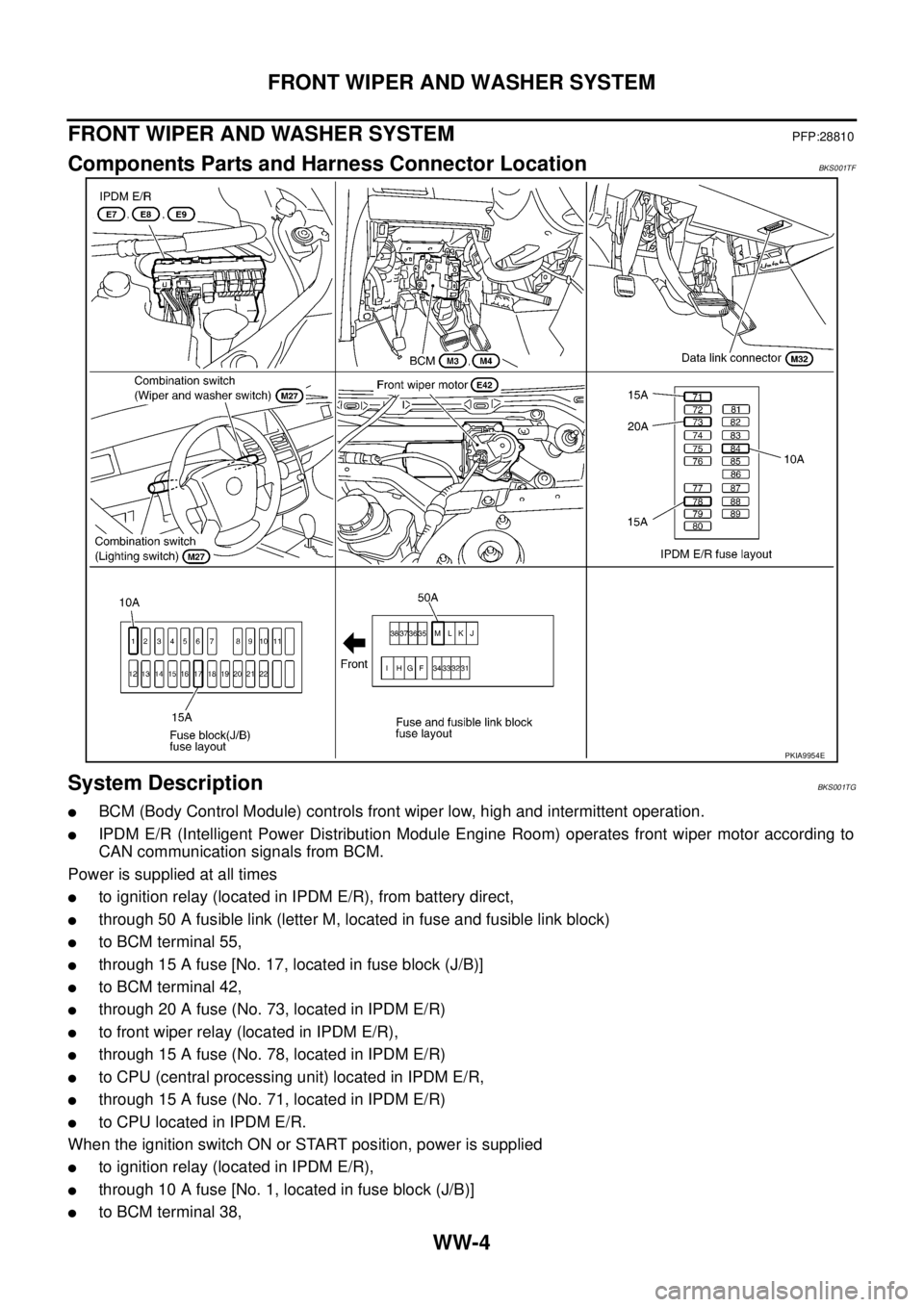
Components Parts and Harness Connector LocationBKS001TF
System DescriptionBKS001TG
�BCM (Body Control Module) controls front wiper low, high and intermittent operation.
�IPDM E/R (Intelligent Power Distribution Module Engine Room) operates front wiper motor according to
CAN communication signals from BCM.
Power is supplied at all times
�to ignition relay (located in IPDM E/R), from battery direct,
�through 50 A fusible link (letter M, located in fuse and fusible link block)
�to BCM terminal 55,
�through 15 A fuse [No. 17, located in fuse block (J/B)]
�to BCM terminal 42,
�through 20 A fuse (No. 73, located in IPDM E/R)
�to front wiper relay (located in IPDM E/R),
�through 15 A fuse (No. 78, located in IPDM E/R)
�to CPU (central processing unit) located in IPDM E/R,
�through 15 A fuse (No. 71, located in IPDM E/R)
�to CPU located in IPDM E/R.
When the ignition switch ON or START position, power is supplied
�to ignition relay (located in IPDM E/R),
�through 10 A fuse [No. 1, located in fuse block (J/B)]
�to BCM terminal 38,
PKIA9954E
Page 3478 of 3502

WW-40
HEADLAMP WASHER
HEADLAMP WASHERPFP:28620
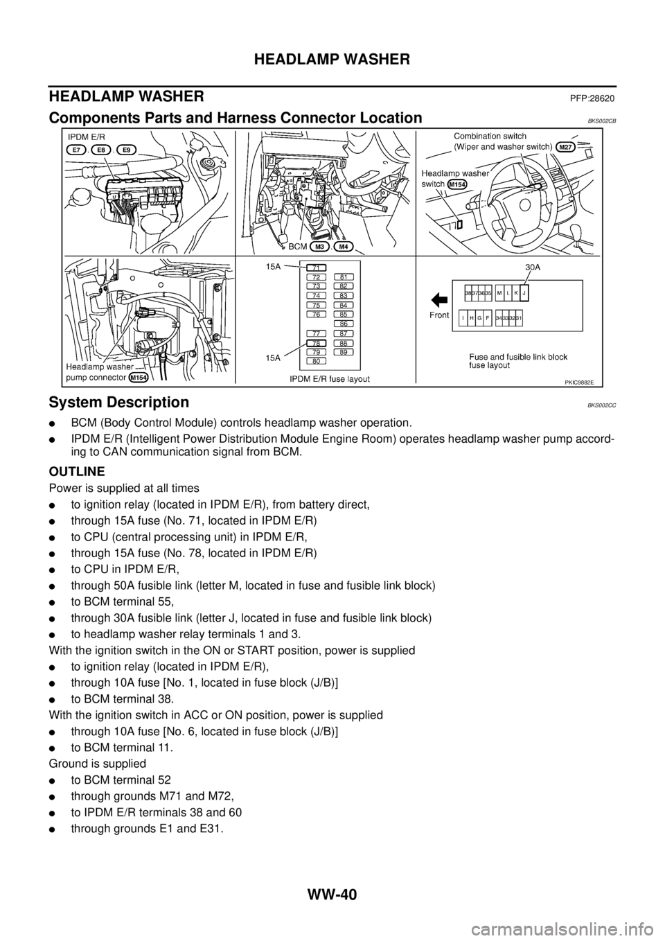
Components Parts and Harness Connector LocationBKS002CB
System DescriptionBKS002CC
�BCM (Body Control Module) controls headlamp washer operation.
�IPDM E/R (Intelligent Power Distribution Module Engine Room) operates headlamp washer pump accord-
ing to CAN communication signal from BCM.
OUTLINE
Power is supplied at all times
�to ignition relay (located in IPDM E/R), from battery direct,
�through 15A fuse (No. 71, located in IPDM E/R)
�to CPU (central processing unit) in IPDM E/R,
�through 15A fuse (No. 78, located in IPDM E/R)
�to CPU in IPDM E/R,
�through 50A fusible link (letter M, located in fuse and fusible link block)
�to BCM terminal 55,
�through 30A fusible link (letter J, located in fuse and fusible link block)
�to headlamp washer relay terminals 1 and 3.
With the ignition switch in the ON or START position, power is supplied
�to ignition relay (located in IPDM E/R),
�through 10A fuse [No. 1, located in fuse block (J/B)]
�to BCM terminal 38.
With the ignition switch in ACC or ON position, power is supplied
�through 10A fuse [No. 6, located in fuse block (J/B)]
�to BCM terminal 11.
Ground is supplied
�to BCM terminal 52
�through grounds M71 and M72,
�to IPDM E/R terminals 38 and 60
�through grounds E1 and E31.
PKIC9882E