Page 3062 of 3502
PG-28
IPDM E/R (INTELLIGENT POWER DISTRIBUTION MODULE ENGINE ROOM)
Removal and Installation of IPDM E/RBKS0024X
REMOVAL
1. Remove IPDM E/R cover A and IPDM E/R cover.
2. While spreading pawls on both side of IPDM E/R cover B,
remove IPDM E/R from IPDM E/R cover B.
3. Remove harness connector from IPDM E/R.
INSTALLATION
Installation is the revers order of removal.
SKIA4048E
Page 3067 of 3502
GROUND
PG-33
C
D
E
F
G
H
I
J
L
MA
B
PG
ENGINE ROOM HARNESS(LH)
CKIM0665E
Page 3069 of 3502
GROUND
PG-35
C
D
E
F
G
H
I
J
L
MA
B
PG
ENGINE ROOM HARNESS(RH)
CKIM0667E
Page 3070 of 3502
PG-36
GROUND
ENGINE CONTROL HARNESS/VQ ENGINE MODELS
CKIM0358E
Page 3071 of 3502
GROUND
PG-37
C
D
E
F
G
H
I
J
L
MA
B
PG
ENGINE CONTROL HARNESS/QR ENGINE MODELS
CKIH0286E
Page 3076 of 3502
PG-42
HARNESS
HARNESS PFP:00011
Harness Layout BKS0024Z
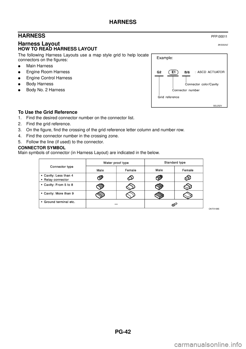
HOW TO READ HARNESS LAYOUT
The following Harness Layouts use a map style grid to help locate
connectors on the figures:
�Main Harness
�Engine Room Harness
�Engine Control Harness
�Body Harness
�Body No. 2 Harness
To Use the Grid Reference
1. Find the desired connector number on the connector list.
2. Find the grid reference.
3. On the figure, find the crossing of the grid reference letter column and number row.
4. Find the connector number in the crossing zone.
5. Follow the line (if used) to the connector.
CONNECTOR SYMBOL
Main symbols of connector (in Harness Layout) are indicated in the below.
SEL252V
CKIT0108E
Page 3081 of 3502
HARNESS
PG-47
C
D
E
F
G
H
I
J
L
MA
B
PG
ENGINE ROOM HARNESS(LH)
Engine Compartment
TKIM0664E
Page 3083 of 3502
HARNESS
PG-49
C
D
E
F
G
H
I
J
L
MA
B
PG
ENGINE ROOM HARNESS(RH)
Engine Compartment
TKIM0666E

Removal and Installation of IPDM E/RBKS0024X
REMOVAL
1. Remove IPDM E/R cover A and IPDM E/R cover.
2. While spreading pawls on bo")

CKIM0665E")

CKIM0667E")


Engine Compartment
TKIM0664E")

Engine Compartment
TKIM0666E")