Page 2310 of 3502
![NISSAN TEANA 2003 Service Manual EM-202
[VQ]
CAMSHAFT
Summary of the inspection items:
* Transmission/transaxle/CVT fluid. power steering fluid, brake fluid, etc.
Valve ClearanceBBS004W2
INSPECTION
In cases of removing/installing o](/manual-img/5/57392/w960_57392-2309.png "NISSAN TEANA 2003 Service Manual EM-202
[VQ]
CAMSHAFT
Summary of the inspection items:
* Transmission/transaxle/CVT fluid. power steering fluid, brake fluid, etc.
Valve ClearanceBBS004W2
INSPECTION
In cases of removing/installing o")
EM-202
[VQ]
CAMSHAFT
Summary of the inspection items:
* Transmission/transaxle/CVT fluid. power steering fluid, brake fluid, etc.
Valve ClearanceBBS004W2
INSPECTION
In cases of removing/installing or replacing camshaft and valve-
related parts, or of unusual engine conditions due to changes in
valve clearance (found malfunctions during stating, idling or causing
noise), perform inspection as follows:
1. Remove rocker covers (right and left banks). Refer to EM-160, "
ROCKER COVER" .
2. Remove splash guard (RH).
3. Measure the valve clearance as follows:
a. Set No. 1 cylinder at TDC of its compression stroke.
�Rotate crankshaft pulley clockwise to align timing mark
(grooved line without color) with timing indicator.
�Make sure that intake and exhaust cam noses on No. 1 cylin-
der (engine front side of right bank) are located as shown in
the figure.
�If not, rotate crankshaft one revolution (360 degrees) and
align as shown in the figure.
Item Before starting engine Engine running After engine stopped
Engine coolant Level Leakage Level
Engine oil Level Leakage Level
Other oils and fluid* Level Leakage Level
Fuel Leakage Leakage Leakage
Exhaust gases — Leakage —
SEM713A
SEM918G
SEM418G
Page 2311 of 3502
![NISSAN TEANA 2003 Service Manual CAMSHAFT
EM-203
[VQ]
C
D
E
F
G
H
I
J
K
L
MA
EM
b. Use feeler gauge, measure the clearance between valve lifter
and camshaft.
Valve clearance:
Unit: mm (in)
*: Approximately 80°C (176°F)
�By referr](/manual-img/5/57392/w960_57392-2310.png "NISSAN TEANA 2003 Service Manual CAMSHAFT
EM-203
[VQ]
C
D
E
F
G
H
I
J
K
L
MA
EM
b. Use feeler gauge, measure the clearance between valve lifter
and camshaft.
Valve clearance:
Unit: mm (in)
*: Approximately 80°C (176°F)
�By referr")
CAMSHAFT
EM-203
[VQ]
C
D
E
F
G
H
I
J
K
L
MA
EM
b. Use feeler gauge, measure the clearance between valve lifter
and camshaft.
Valve clearance:
Unit: mm (in)
*: Approximately 80°C (176°F)
�By referring to the figure, measure the valve clearances at
locations marked “×” as shown in the table below (locations
indicated in the figure) with feeler gauge.
�No. 1 cylinder at compression TDC
c. Rotate crankshaft by 240 degrees clockwise (when viewed from engine front) to align No. 3 cylinder at
TDC of its compression stroke.
NOTE:
�To align cylinder No.3 with the compression top dead center,
place matching marks (A) on the crank pulley (1) side and on
the cylinder block side at a point 240°counterclockwise from
the compression top dead center using the hex head of the
crank pulley mounting bolt as aguide.
SEM139D
Cold Hot * (reference data)
Intake 0.26 - 0.34 (0.010 - 0.013) 0.304 - 0.416 (0.012 - 0.016)
Exhaust 0.29 - 0.37 (0.011 - 0.015) 0.308 - 0.432 (0.012 - 0.017)
Measuring position (right bank) No. 1 CYL. No. 3 CYL. No. 5 CYL.
No. 1 cylinder at
compression TDCEXH×
INT×
Measuring position (left bank) No. 2 CYL. No. 4 CYL. No. 6 CYL.
No. 1 cylinder at
compression TDCINT×
EXH×
PBIC2054E
PBIC4628J
Page 2312 of 3502
EM-204
[VQ]
CAMSHAFT
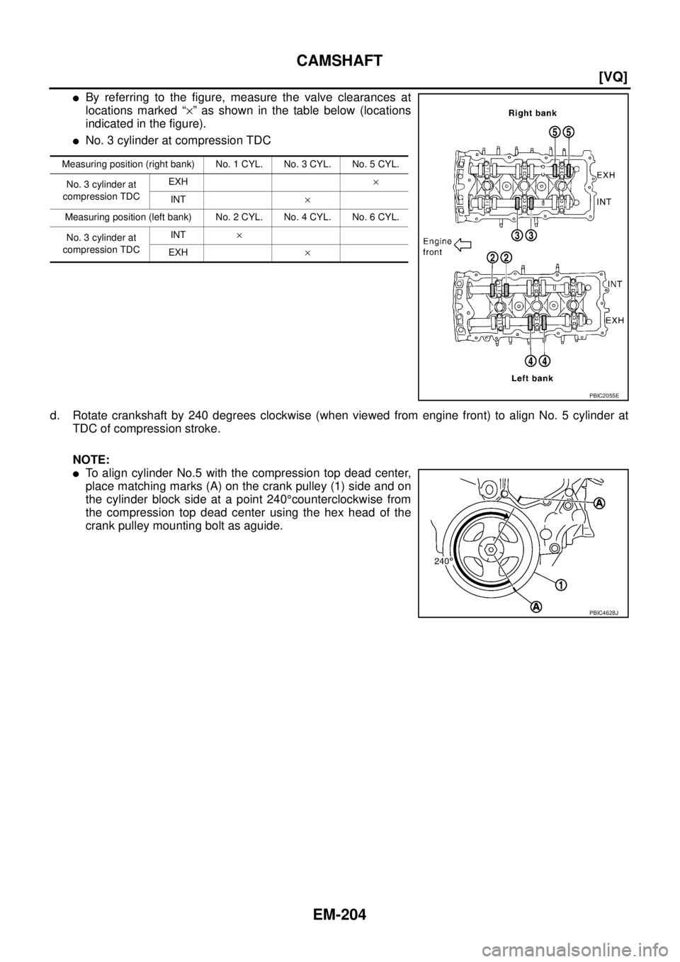
�By referring to the figure, measure the valve clearances at
locations marked “×” as shown in the table below (locations
indicated in the figure).
�No. 3 cylinder at compression TDC
d. Rotate crankshaft by 240 degrees clockwise (when viewed from engine front) to align No. 5 cylinder at
TDC of compression stroke.
NOTE:
�To align cylinder No.5 with the compression top dead center,
place matching marks (A) on the crank pulley (1) side and on
the cylinder block side at a point 240°counterclockwise from
the compression top dead center using the hex head of the
crank pulley mounting bolt as aguide.
Measuring position (right bank) No. 1 CYL. No. 3 CYL. No. 5 CYL.
No. 3 cylinder at
compression TDCEXH×
INT×
Measuring position (left bank) No. 2 CYL. No. 4 CYL. No. 6 CYL.
No. 3 cylinder at
compression TDCINT×
EXH ×
PBIC2055E
PBIC4628J
Page 2314 of 3502
![NISSAN TEANA 2003 Service Manual EM-206
[VQ]
CAMSHAFT
�Thickness of new valve lifter can be identified by stamp marks
on the reverse side (inside the cylinder).
VQ23DE
Available thickness of valve lifter: 27 sizes with range 6.66](/manual-img/5/57392/w960_57392-2313.png "NISSAN TEANA 2003 Service Manual EM-206
[VQ]
CAMSHAFT
�Thickness of new valve lifter can be identified by stamp marks
on the reverse side (inside the cylinder).
VQ23DE
Available thickness of valve lifter: 27 sizes with range 6.66")
EM-206
[VQ]
CAMSHAFT
�Thickness of new valve lifter can be identified by stamp marks
on the reverse side (inside the cylinder).
VQ23DE
Available thickness of valve lifter: 27 sizes with range 6.66 to 7.18 mm (0.2622 to 0.2827 in) in steps of
0.02 mm (0.0008 in) (when manufactured at factory). Refer to EM-258, "
Available Valve Lifter" .
VQ35DE
Available thickness of valve lifter: 27 sizes with range 7.88 to 8.40 mm (0.3102 to 0.3307 in) in steps of
0.02 mm (0.0008 in) (when manufactured at factory). Refer to EM-258, "
Available Valve Lifter" .
CAUTION:
Install identification letter at the end, “U” and “R”, at each of proper positions. (Be careful of
mis-installation between intake and exhaust)
5. Install selected valve lifter.
6. Install camshaft. Refer to EM-197, "
INSTALLATION" .
7. Manually rotate crankshaft pulley a few rotations.
8. Make sure that the valve clearances for cold engine are within the specifications by referring to the speci-
fied values. Refer to EM-202, "
INSPECTION" .
9. Install all removed parts in the reverse order of removal. Refer to EM-197, "
INSTALLATION" .
10. Warm up the engine, and check for unusual noise and vibration.
KBIA0119E
Stamp mark
Thickness
INT EXH
666U 6.66 mm
668U 6.68 mm
··
··
718U 7.18 mm
Stamp mark
Thickness
INT EXH
788U 788R 7.88 mm
790U 790R 7.90 mm
·· ·
·· ·
840U 840R 8.40 mm
Page 2315 of 3502
![NISSAN TEANA 2003 Service Manual OIL SEAL
EM-207
[VQ]
C
D
E
F
G
H
I
J
K
L
MA
EM
OIL SEALPFP:00100
Removal and Installation of Valve Oil SealBBS004W3
REMOVAL
1. Remove engine assembly from vehicle, and separate front suspension memb](/manual-img/5/57392/w960_57392-2314.png "NISSAN TEANA 2003 Service Manual OIL SEAL
EM-207
[VQ]
C
D
E
F
G
H
I
J
K
L
MA
EM
OIL SEALPFP:00100
Removal and Installation of Valve Oil SealBBS004W3
REMOVAL
1. Remove engine assembly from vehicle, and separate front suspension memb")
OIL SEAL
EM-207
[VQ]
C
D
E
F
G
H
I
J
K
L
MA
EM
OIL SEALPFP:00100
Removal and Installation of Valve Oil SealBBS004W3
REMOVAL
1. Remove engine assembly from vehicle, and separate front suspension member and transaxle from
engine. Refer to EM-223, "
ENGINE ASSEMBLY" .
2. Install engine sub-attachment with engine stand shaft [SST: KV10117001 and KV10106500] to right side
of cylinder block, then lift engine, and mount it onto engine stand [SST: ST0501S000]. Refer to EM-228,
"CYLINDER BLOCK" .
3. Remove camshaft relating to valve oil seal to be removed. Refer to EM-192, "
CAMSHAFT" .
4. Remove valve lifters. Refer to EM-192, "
CAMSHAFT" .
5. Rotate crankshaft until the cylinder requiring new oil seals is at TDC. This will prevent valve from dropping
into cylinder.
6. Remove valve collet.
�Compress valve spring with valve spring compressor, attach-
ment, adapter (SST). Remove valve collet with magnet hand.
CAUTION:
When working, take care not to damage valve lifter holes.
7. Remove valve spring retainer and valve spring.
8. Remove valve oil seal using valve oil seal puller (SST).
INSTALLATION
1. Apply engine oil on new valve oil seal joint and seal lip.
2. Using valve oil seal drift (SST), press-fit valve seal to height “H”
shown in the figure.
NOTE:
Dimension “H”: Height measured before valve spring seat instal-
lation
3. Install in the reverse order of removal after this step.
PBIC1791E
PBIC1610E
Intake and exhaust : 14.3 - 14.9 mm (0.563 - 0.587 in)
PBIC1611E
Page 2316 of 3502
![NISSAN TEANA 2003 Service Manual EM-208
[VQ]
OIL SEAL
Removal and Installation of Front Oil SealBBS004W4
REMOVAL
1. Remove the following:
�Right side front road wheel and tire.
�Splash guard (RH)
�Drive belts; Refer to EM-128, "DRI](/manual-img/5/57392/w960_57392-2315.png "NISSAN TEANA 2003 Service Manual EM-208
[VQ]
OIL SEAL
Removal and Installation of Front Oil SealBBS004W4
REMOVAL
1. Remove the following:
�Right side front road wheel and tire.
�Splash guard (RH)
�Drive belts; Refer to EM-128, \"DRI")
EM-208
[VQ]
OIL SEAL
Removal and Installation of Front Oil SealBBS004W4
REMOVAL
1. Remove the following:
�Right side front road wheel and tire.
�Splash guard (RH)
�Drive belts; Refer to EM-128, "DRIVE BELTS" .
�Crankshaft pulley; Refer to EM-173, "TIMING CHAIN" .
2. Remove front oil seal using suitable tool.
CAUTION:
Be careful not to damage front timing chain case and crank-
shaft.
INSTALLATION
1. Apply engine oil to both oil seal lip and dust seal lip.
2. Install front oil seal.
�Install front oil seal so that each seal lip is oriented as shown
in the figure.
�Using suitable drift, press-fit until the height of front oil seal is
level with the mounting surface.
–Suitable drift: outer diameter 60 mm (2.36 in), inner diameter
50 mm (1.97 in).
CAUTION:
�Be careful not to damage front timing chain case and
crankshaft.
�Press-fit straight and avoid causing burrs or tilting oil
seal.
3. Install in the reverse order of removal after this step.
Removal and Installation of Rear Oil SealBBS004W5
REMOVAL
1. Remove engine assembly from vehicle, and separate front suspension member and transaxle from
engine. Refer to EM-223, "
ENGINE ASSEMBLY" .
2. Install engine sub-attachment with engine stand shaft [SST: KV10117001 and KV10106500] to right side
of cylinder block, then lift engine, and mount it onto engine stand [SST: ST0501S000]. Refer to EM-228,
"CYLINDER BLOCK" .
3. Remove drive plate. Refer to EM-228, "
CYLINDER BLOCK" .
4. Remove oil pan (upper). Refer to EM-145, "
OIL PAN AND OIL STRAINER" .
SEM829E
SEM715A
SEM829E
Page 2317 of 3502
OIL SEAL
EM-209
[VQ]
C
D
E
F
G
H
I
J
K
L
MA
EM
5. Use seal cutter (SST) to cut away liquid gasket and remove rear
oil seal retainer.
CAUTION:
Be careful not to damage mating surfaces.
NOTE:
Regard both rear oil seal and retainer as an assembly.
INSTALLATION
1. Remove old liquid gasket on mating surface of cylinder block and oil pan (upper) using scraper.
2. Apply new engine oil to both oil seal lip and dust seal lip of new rear oil seal retainer.
3. Apply a continuous bead of liquid gasket with tube presser [SST:
WS39930000] to new rear oil seal retainer as shown in the fig-
ure.
Use Genuine Liquid Gasket or equivalent.
�Assembly should be done within 5 minutes after coating.
4. Install rear oil seal retainer to cylinder block. Refer to EM-228, "
CYLINDER BLOCK" .
5. Install in the reverse order of removal after this step.
PBIC1612E
PBIC2649E
Page 2318 of 3502
![NISSAN TEANA 2003 Service Manual EM-210
[VQ]
CYLINDER HEAD
CYLINDER HEADPFP:11041
On-Vehicle ServiceBBS004W6
CHECKING COMPRESSION PRESSURE
1. Warm up engine thoroughly. Then, stop it.
2. Release fuel pressure. Refer to EC-392, "
FU](/manual-img/5/57392/w960_57392-2317.png "NISSAN TEANA 2003 Service Manual EM-210
[VQ]
CYLINDER HEAD
CYLINDER HEADPFP:11041
On-Vehicle ServiceBBS004W6
CHECKING COMPRESSION PRESSURE
1. Warm up engine thoroughly. Then, stop it.
2. Release fuel pressure. Refer to EC-392, \"
FU")
EM-210
[VQ]
CYLINDER HEAD
CYLINDER HEADPFP:11041
On-Vehicle ServiceBBS004W6
CHECKING COMPRESSION PRESSURE
1. Warm up engine thoroughly. Then, stop it.
2. Release fuel pressure. Refer to EC-392, "
FUEL PRESSURE RELEASE" .
3. Disconnect fuel pump fuse to avoid fuel injection during mea-
surement.
4. Remove engine cover. Refer to EM-133, "
INTAKE MANIFOLD COLLECTOR" .
5. Remove ignition coil and spark plug from each cylinder. Refer to EM-152, "
IGNITION COIL" and EM-153,
"SPARK PLUG (PLATINUM-TIPPED TYPE)" .
6. Connect engine tachometer (not required in use of CONSULT-ll).
7. Install compression tester with adapter onto spark plug hole.
�Use compression gauge whose picking up end inserted to
spark plug hole is smaller than 20 mm (0.79 in) in diameter.
Otherwise, it may be caught by cylinder head during removal.
8. With accelerator pedal fully depressed, turn ignition switch to “START” for cranking. When the gauge
pointer stabilizes, read the compression pressure and engine rpm. Perform these steps to check each cyl-
inder.
Compression pressure:
Unit: kPa (bar, kg/cm2 , psi) /rpm
PBIB2110E
PBIC0900E
SBIA0533E
VQ23DE VQ35DE
Standard 1,050 (10.5, 10.7, 152) / 300 1,270 (12.70, 13.0, 184) / 300
Minimum 750 (7.5, 7.7, 109) / 300 980 (9.8, 10.0, 142) / 300
Differential limit between cylinders 100 (1.0, 1.0, 15) / 300 100 (1.0, 1.0, 15) / 300
![NISSAN TEANA 2003 Service Manual OIL SEAL
EM-209
[VQ]
C
D
E
F
G
H
I
J
K
L
MA
EM
5. Use seal cutter (SST) to cut away liquid gasket and remove rear
oil seal retainer.
CAUTION:
Be careful not to damage mating surfaces.
NOTE:
Regard b](/manual-img/5/57392/w960_57392-2316.png "NISSAN TEANA 2003 Service Manual OIL SEAL
EM-209
[VQ]
C
D
E
F
G
H
I
J
K
L
MA
EM
5. Use seal cutter (SST) to cut away liquid gasket and remove rear
oil seal retainer.
CAUTION:
Be careful not to damage mating surfaces.
NOTE:
Regard b")