2003 NISSAN ALMERA N16 clutch
[x] Cancel search: clutchPage 1412 of 3189
NJMT0009
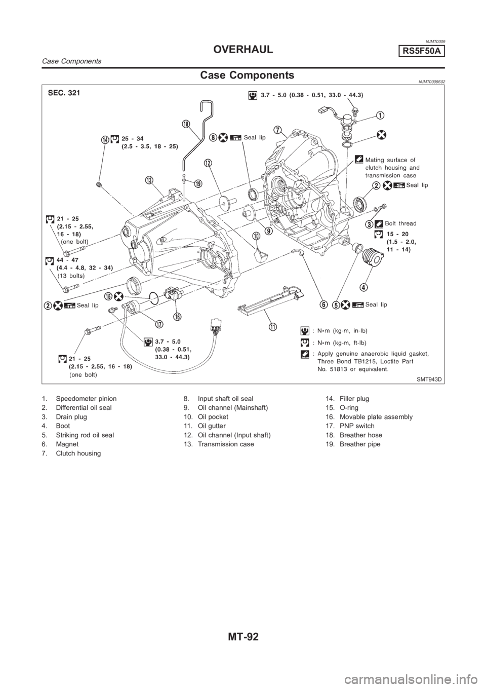
Case ComponentsNJMT0009S02
SMT943D
1. Speedometer pinion
2. Differential oil seal
3. Drain plug
4. Boot
5. Striking rod oil seal
6. Magnet
7. Clutch housing8. Input shaft oil seal
9. Oil channel (Mainshaft)
10. Oil pocket
11. Oil gutter
12. Oil channel (Input shaft)
13. Transmission case14. Filler plug
15. O-ring
16. Movable plate assembly
17. PNP switch
18. Breather hose
19. Breather pipe
OVERHAULRS5F50A
Case Components
MT-92
Page 1416 of 3189
SMT662C
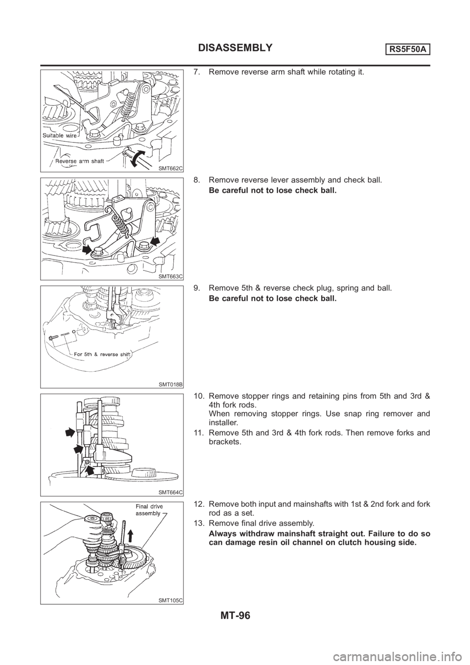
7. Remove reverse arm shaft while rotating it.
SMT663C
8. Remove reverse lever assembly and check ball.
Be careful not to lose check ball.
SMT018B
9. Remove 5th & reverse check plug, spring and ball.
Be careful not to lose check ball.
SMT664C
10. Remove stopper rings and retaining pins from 5th and 3rd &
4th fork rods.
When removing stopper rings. Use snap ring remover and
installer.
11. Remove 5th and 3rd & 4th fork rods. Then remove forks and
brackets.
SMT105C
12. Remove both input and mainshafts with 1st & 2nd fork and fork
rod as a set.
13. Remove final drive assembly.
Always withdraw mainshaft straight out. Failure to do so
can damage resin oil channel on clutch housing side.
DISASSEMBLYRS5F50A
MT-96
Page 1431 of 3189
NJMT0022
Input Shaft End Play and Differential Side
Bearing Preload
NJMT0022S01If any of the following parts are replaced, adjust input shaft end
play.
Input shaft
Input shaft bearing
Clutch housing
Transmission case
If any of the following parts are replaced, adjust differential side
bearing preload.
Differential case
Differential side bearing
Clutch housing
Transmission case
SMT132AA
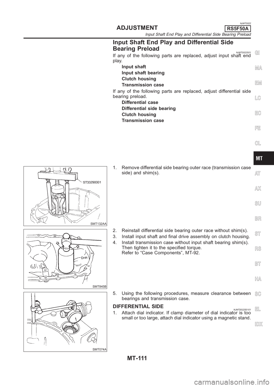
1. Remove differential side bearing outer race (transmission case
side) and shim(s).
SMT845B
2. Reinstall differential side bearing outer race without shim(s).
3. Install input shaft and final drive assembly on clutch housing.
4. Install transmission case without input shaft bearing shim(s).
Then tighten it to the specified torque.
Refer to “Case Components”, MT-92.
SMT074A
5. Using the following procedures, measure clearance between
bearings and transmission case.
DIFFERENTIAL SIDENJMT0022S01011. Attach dial indicator. If clamp diameter of dial indicator is too
small or too large, attach dial indicator using a magnetic stand.
GI
MA
EM
LC
EC
FE
CL
AT
AX
SU
BR
ST
RS
BT
HA
SC
EL
IDX
ADJUSTMENTRS5F50A
Input Shaft End Play and Differential Side Bearing Preload
MT-111
Page 1432 of 3189
SMT075AA
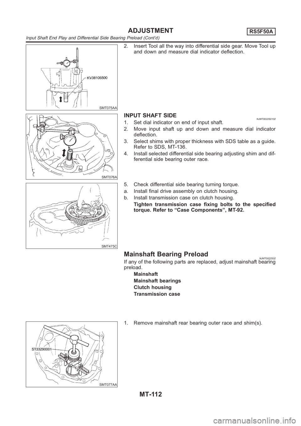
2. Insert Tool all the way into differential side gear. Move Tool up
and down and measure dial indicator deflection.
SMT076A
INPUTSHAFTSIDENJMT0022S01021. Set dial indicator on end of input shaft.
2. Move input shaft up and down and measure dial indicator
deflection.
3. Select shims with proper thickness with SDS table as a guide.
Refer to SDS, MT-136.
4. Install selected differential side bearing adjusting shim and dif-
ferential side bearing outer race.
SMT475C
5. Check differential side bearing turning torque.
a. Install final drive assembly on clutch housing.
b. Install transmission case on clutch housing.
Tighten transmission case fixing bolts to the specified
torque. Refer to “Case Components”, MT-92.
Mainshaft Bearing PreloadNJMT0022S02If any of the following parts are replaced, adjust mainshaft bearing
preload.
Mainshaft
Mainshaft bearings
Clutch housing
Transmission case
SMT077AA
1. Remove mainshaft rear bearing outer race and shim(s).
ADJUSTMENTRS5F50A
Input Shaft End Play and Differential Side Bearing Preload (Cont’d)
MT-112
Page 1433 of 3189
SMT644AA
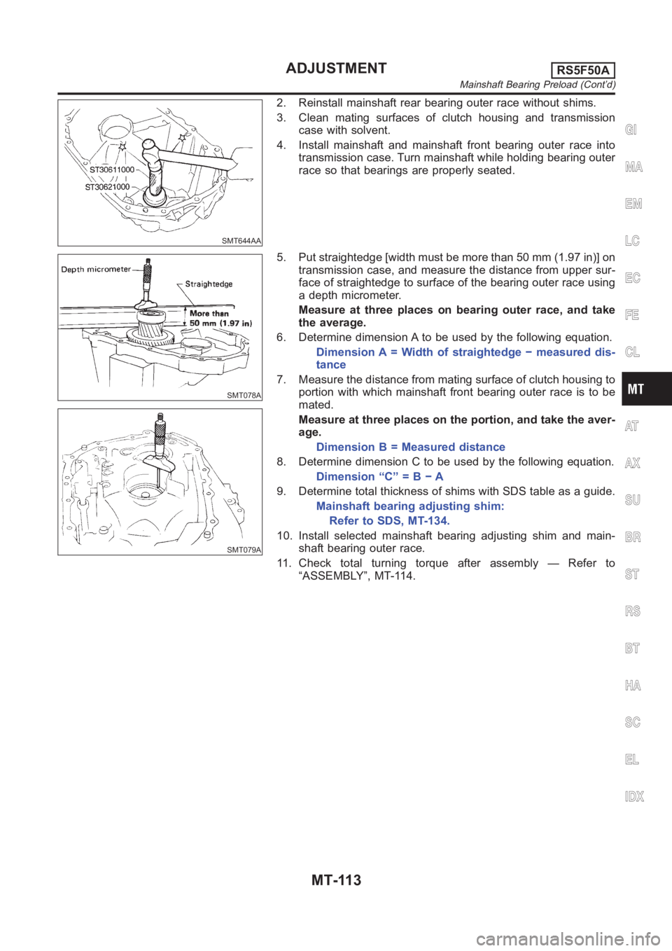
2. Reinstall mainshaft rear bearing outer race without shims.
3. Clean mating surfaces of clutch housing and transmission
case with solvent.
4. Install mainshaft and mainshaft front bearing outer race into
transmission case. Turn mainshaft while holding bearing outer
race so that bearings are properly seated.
SMT078A
SMT079A
5. Put straightedge [width must be more than 50 mm (1.97 in)] on
transmission case, and measure the distance from upper sur-
face of straightedge to surface of the bearing outer race using
a depth micrometer.
Measure at three places on bearing outer race, and take
the average.
6. Determine dimension A to be used by the following equation.
Dimension A = Width of straightedge − measured dis-
tance
7. Measure the distance from mating surface of clutch housing to
portion with which mainshaft front bearing outer race is to be
mated.
Measure at three places on the portion, and take the aver-
age.
Dimension B = Measured distance
8. Determine dimension C to be used by the following equation.
Dimension “C” = B − A
9. Determine total thickness of shims with SDS table as a guide.
Mainshaft bearing adjusting shim:
Refer to SDS, MT-134.
10. Install selected mainshaft bearing adjusting shim and main-
shaft bearing outer race.
11. Check total turning torque after assembly — Refer to
“ASSEMBLY”, MT-114.
GI
MA
EM
LC
EC
FE
CL
AT
AX
SU
BR
ST
RS
BT
HA
SC
EL
IDX
ADJUSTMENTRS5F50A
Mainshaft Bearing Preload (Cont’d)
MT-113
Page 1436 of 3189
SMT667C
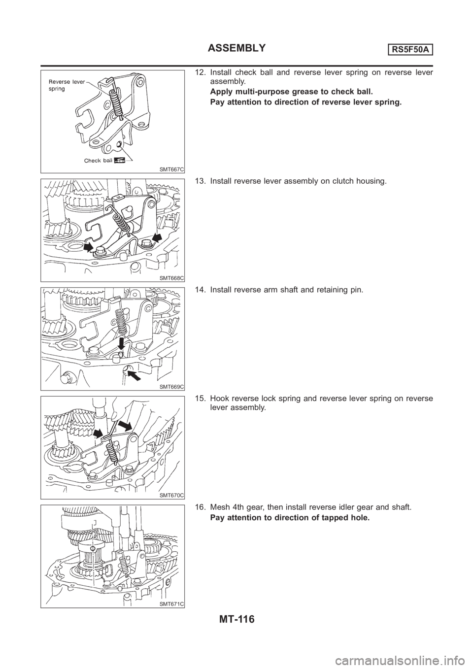
12. Install check ball and reverse lever spring on reverse lever
assembly.
Apply multi-purpose grease to check ball.
Pay attention to direction of reverse lever spring.
SMT668C
13. Install reverse lever assembly on clutch housing.
SMT669C
14. Install reverse arm shaft and retaining pin.
SMT670C
15. Hook reverse lock spring and reverse lever spring on reverse
lever assembly.
SMT671C
16. Mesh 4th gear, then install reverse idler gear and shaft.
Pay attention to direction of tapped hole.
ASSEMBLYRS5F50A
MT-116
Page 1437 of 3189
SMT070A
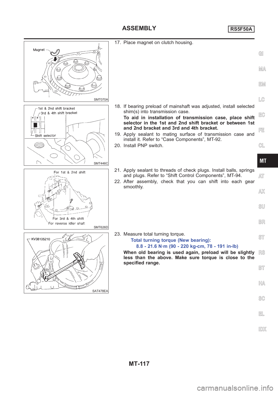
17. Place magnet on clutch housing.
SMT446C
18. If bearing preload of mainshaft was adjusted, install selected
shim(s) into transmission case.
To aid in installation of transmission case, place shift
selector in the 1st and 2nd shift bracket or between 1st
and 2nd bracket and 3rd and 4th bracket.
19. Apply sealant to mating surface of transmission case and
install it. Refer to “Case Components”, MT-92.
20. Install PNP switch.
SMT626D
21. Apply sealant to threads of check plugs. Install balls, springs
and plugs. Refer to “Shift Control Components”, MT-94.
22. After assembly, check that you can shift into each gear
smoothly.
SAT478EA
23. Measure total turning torque.
Total turning torque (New bearing):
8.8 - 21.6 N·m (90 - 220 kg-cm, 78 - 191 in-lb)
When old bearing is used again, preload will be slightly
less than the above. Make sure torque is close to the
specified range.
GI
MA
EM
LC
EC
FE
CL
AT
AX
SU
BR
ST
RS
BT
HA
SC
EL
IDX
ASSEMBLYRS5F50A
MT-117
Page 1458 of 3189
AT-2
Diagnostic Procedure ...........................................137
Component Inspection ..........................................138
DTC P0732 A/T 2ND GEAR FUNCTION ................139
Description ............................................................139
Wiring Diagram — AT — 2ND ..............................142
Diagnostic Procedure ...........................................143
Component Inspection ..........................................144
DTC P0733 A/T 3RD GEAR FUNCTION ................145
Description ............................................................145
Wiring Diagram — AT — 3RD ..............................148
Diagnostic Procedure ...........................................149
Component Inspection ..........................................150
DTC P0734 A/T 4TH GEAR FUNCTION ................151
Description ............................................................151
Wiring Diagram — AT — 4TH ...............................154
Diagnostic Procedure ...........................................155
Component Inspection ..........................................158
DTC P0740 TORQUE CONVERTER CLUTCH
SOLENOID VALVE .................................................159
Description ............................................................159
Wiring Diagram — AT — TCV ..............................161
Diagnostic Procedure ...........................................162
Component Inspection ..........................................163
DTC P0745 LINE PRESSURE SOLENOID VALVE .164
Description ............................................................164
Wiring Diagram — AT — LPSV ............................166
Diagnostic Procedure ...........................................167
Component Inspection ..........................................169
DTC P0750 SHIFT SOLENOID VALVE A ...............171
Description ............................................................171
Wiring Diagram — AT — SSV/A ...........................173
Diagnostic Procedure ...........................................174
Component Inspection ..........................................175
DTC P0755 SHIFT SOLENOID VALVE B ...............176
Description ............................................................176
Wiring Diagram — AT — SSV/B ...........................178
Diagnostic Procedure ...........................................179
Component Inspection ..........................................179
DTC P1705 ACCELERATOR PEDAL POSITION
(APP) SENSOR .......................................................181
Description ............................................................181
Wiring Diagram — AT — TPS ..............................184
Diagnostic Procedure ...........................................185
DTC P1760 OVERRUN CLUTCH SOLENOID
VALVE .....................................................................187
Description ............................................................187
Wiring Diagram — AT — OVRCSV ......................189
Diagnostic Procedure ...........................................190
Component Inspection ..........................................191
DTC U1000 CAN COMMUNICATION LINE ............192
Description ............................................................192
On Board Diagnosis Logic ....................................192
DTC Confirmation Procedure ...............................192
Wiring Diagram — AT ...........................................193
Diagnostic Procedure ...........................................194
DTC BATT/FLUID TEMP SEN (A/T FLUID TEMP
SENSOR CIRCUIT AND TCM POWER SOURCE) .195
Description ............................................................195
Wiring Diagram — AT — BA/FTS .........................197Diagnostic Procedure ............................................198
Component Inspection ..........................................200
DTC VEHICLE SPEED SENSOR MTR ...................201
Description ............................................................201
Wiring Diagram — AT — VSSMTR .......................203
Diagnostic Procedure ............................................204
DTC CONTROL UNIT (RAM), CONTROL UNIT
(ROM) ......................................................................205
Description ............................................................205
Diagnostic Procedure ............................................206
DTC CONTROL UNIT (EEP ROM) .........................207
Description ............................................................207
Diagnostic Procedure ............................................208
TROUBLE DIAGNOSES FOR SYMPTOMS ...........209
Wiring Diagram — AT — NONDTC ......................209
1. O/D OFF Indicator Lamp Does Not Come On ..211
2. Engine Cannot Be Started In “P” and “N” Position .212
3. In “P” Position, Vehicle Moves Forward Or Back-
ward When Pushed ...............................................213
4. In “N” Position, Vehicle Moves ..........................214
5. Large Shock. “N” → “R” Position ......................215
6. Vehicle Does Not Creep Backward In “R” Position .216
7. Vehicle Does Not Creep Forward In “D”, “2” Or
“1” Position ............................................................219
8. Vehicle Cannot Be Started From D
1 .................221
9. A/T Does Not Shift: D
1→ D2 Or Does Not Kick-
down: D
4→ D2 .....................................................223
10. A/T Does Not Shift: D
2→ D3 ..........................225
11. A/T Does Not Shift: D
3→ D4 ...........................227
12. A/T Does Not Perform Lock-up .......................230
13. A/T Does Not Hold Lock-up Condition ............231
14. Lock-up Is Not Released .................................232
15. Engine Speed Does Not Return To Idle (Light
Braking D
4→ D3 ) .................................................233
16. Vehicle Does Not Start From D
1 .....................234
17. A/T Does Not Shift: D
4→ D3 , W h e n O v e r d r i v e
Control Switch “ON” → “OFF” ...............................235
18. A/T Does Not Shift: D
3→ 22 , When Selector
Lever “D” → “2” Position .......................................235
19. A/T Does Not Shift: 2
2→ 11 , When Selector
Lever “2” → “1” Position ........................................236
20. Vehicle Does Not Decelerate By Engine Brake .237
21. TCM Self-diagnosis Does Not Activate (PNP &
Overdrive Control Switches, and Throttle Position
Sensor Circuit Checks) .........................................237
EXC.F/EURO-OBD
ON BOARD DIAGNOSTIC SYSTEM DESCRIP-
TION ........................................................................244
CONSULT-II ..........................................................244
Diagnostic Procedure Without CONSULT-II .........250
TROUBLE DIAGNOSIS — INTRODUCTION .........255
Introduction ...........................................................255
Work Flow .............................................................259
TROUBLE DIAGNOSIS — BASIC INSPECTION ...261
A/T Fluid Check ....................................................261
Stall Test ................................................................262