2003 NISSAN ALMERA N16 set clock
[x] Cancel search: set clockPage 110 of 3189
![NISSAN ALMERA N16 2003 Electronic Repair Manual EM-32
[QG]
CAMSHAFT
CAMSHAFT
PFP:13001
Removal and InstallationEBS00LQB
CAUTION:
Prior to installation, apply engine oil to the parts marked in the figure.
REMOVAL
1. Remove rocker cover. Refer to EM- NISSAN ALMERA N16 2003 Electronic Repair Manual EM-32
[QG]
CAMSHAFT
CAMSHAFT
PFP:13001
Removal and InstallationEBS00LQB
CAUTION:
Prior to installation, apply engine oil to the parts marked in the figure.
REMOVAL
1. Remove rocker cover. Refer to EM-](/manual-img/5/57350/w960_57350-109.png)
EM-32
[QG]
CAMSHAFT
CAMSHAFT
PFP:13001
Removal and InstallationEBS00LQB
CAUTION:
Prior to installation, apply engine oil to the parts marked in the figure.
REMOVAL
1. Remove rocker cover. Refer to EM-29, "ROCKER COVER" .
2. Remove cylinder head front cover.
●Move harness secured to front surface beforehand.
3. Set No. 1 cylinder at TDC of its compression stroke.
a. Remove RH splash cover (integrated with undercover).
b. Rotate crankshaft pulley clockwise and align yellow paint mark
with timing indicator.
PBIC0965E
1. Camshaft bracket 2. Camshaft sprocket (INT) 3. Camshaft sprocket (EXH)
4. Washer 5. Cylinder head front cover 6. Chain tensioner
7. Valve lifter 8. Adjusting shim (If so equipped) 9. Camshaft (EXH)
10. Camshaft (INT)
MBIB0193E
Page 112 of 3189
![NISSAN ALMERA N16 2003 Electronic Repair Manual EM-34
[QG]
CAMSHAFT
c. Slowly turn intake camshaft in direction A (counterclockwise:
intake manifold side).
●Perform while applying air pressure.
CAUTION:
Be careful not to dislocate camshaft retain NISSAN ALMERA N16 2003 Electronic Repair Manual EM-34
[QG]
CAMSHAFT
c. Slowly turn intake camshaft in direction A (counterclockwise:
intake manifold side).
●Perform while applying air pressure.
CAUTION:
Be careful not to dislocate camshaft retain](/manual-img/5/57350/w960_57350-111.png)
EM-34
[QG]
CAMSHAFT
c. Slowly turn intake camshaft in direction A (counterclockwise:
intake manifold side).
●Perform while applying air pressure.
CAUTION:
Be careful not to dislocate camshaft retaining spanner.
d. During above step, operating click (a sound indicating internal
lock pin is disengaged) is heard from inside of intake camshaft
sprocket. After hearing it, slowly turn intake camshaft in direction
B (clockwise: exhaust manifold side), and set to most advanced
position.
●Perform while applying air pressure.
●When vane rotates solely against sprocket, lock pin is disengaged even if operating click is not heard.
●If lock pin is not disengaged, apply vibration by jiggling the camshaft with a spanner.
●If lock pin is not disengaged with above step, hit intake camshaft in front by using plastic hammer.
e. The following status indicates that most advanced position is
achieved: vane starts rotating on its own, then sprocket also
starts rotating when camshaft is turned. When above status is
achieved, this step is complete.
●Most advanced position is confirmed when stopper pin groove
and lock pin breathing groove are aligned.
f. Stop air, insert stopper pin [approximately 3 mm (0.12 in) dia.,
length of inserted part is approximately 15 mm (0.59 in)] into
pinhole on camshaft sprocket to fix most advanced position.
NOTE:
In the figure, an Allen wrench [a/f 2.5 mm (0.091 in), short part:
approximately 20 mm (0.79 in), long part: approximately 50 mm
(1.97 in)] is used for stopper pin as an example.
CAUTION:
Load (spring reaction force) is not applied to stopper pin.
Pin is easily detached. Therefore, secure it with vinyl tape to
prevent detachment.
5. Remove chain tensioner.
●Remove in the following order.
a. Press plate down, and release stopper tab.
b. Insert plunger into tensioner body until it stops.
c. Secure plate by passing stopper pin (such as a hard wire)
through plate hole and body hole. (Plunger is also secured.)
d. Remove mounting bolts, and remove chain tensioner.
KBIA1414J
MBIB0198E
PBIC0966E
MBIB0201E
Page 116 of 3189
![NISSAN ALMERA N16 2003 Electronic Repair Manual EM-38
[QG]
CAMSHAFT
8. Remove stopper pin from intake camshaft sprocket.
9. Slowly turn crankshaft pulley clockwise to set intake camshaft
sprocket to most retarded position.
●Sprocket begin NISSAN ALMERA N16 2003 Electronic Repair Manual EM-38
[QG]
CAMSHAFT
8. Remove stopper pin from intake camshaft sprocket.
9. Slowly turn crankshaft pulley clockwise to set intake camshaft
sprocket to most retarded position.
●Sprocket begin](/manual-img/5/57350/w960_57350-115.png)
EM-38
[QG]
CAMSHAFT
8. Remove stopper pin from intake camshaft sprocket.
9. Slowly turn crankshaft pulley clockwise to set intake camshaft
sprocket to most retarded position.
●Sprocket begins turning after crankshaft does. Once sprocket
starts turning, keep turning crankshaft until the vane (cam-
shaft) also begins turning. Most retarded position should now
be achieved.
●Most retarded position is confirmed when stopper pin groove
is at a clockwise offset from lock pin breathing groove.
●While turning crankshaft slightly more counterclockwise, con-
firm that lock pin is engaged when vane and sprocket turn
together.
10. Install cylinder head front cover.
●Apply liquid gasket (Use Genuine Liquid Gasket or equiva-
lent) continuously as shown in figure.
●Install it by aligning dowel pin on cylinder head.
11. Check and adjust valve clearance. Refer to EM-42, "
Va l v e
Clearance" .
12. From this step, install in the reverse order of removal.
PBIC0966E
MBIB0213E
MBIB0214E
PBIC0968E
Page 126 of 3189
![NISSAN ALMERA N16 2003 Electronic Repair Manual EM-48
[QG]
TIMING CHAIN
2. Disconnect battery ground cable.
3. Remove undercover, front RH wheel and RH splash cover.
4. Drain engine coolant from radiator and cylinder block. Refer to LC-17, "Cha NISSAN ALMERA N16 2003 Electronic Repair Manual EM-48
[QG]
TIMING CHAIN
2. Disconnect battery ground cable.
3. Remove undercover, front RH wheel and RH splash cover.
4. Drain engine coolant from radiator and cylinder block. Refer to LC-17, "Cha](/manual-img/5/57350/w960_57350-125.png)
EM-48
[QG]
TIMING CHAIN
2. Disconnect battery ground cable.
3. Remove undercover, front RH wheel and RH splash cover.
4. Drain engine coolant from radiator and cylinder block. Refer to LC-17, "Changing Engine Coolant".
5. Drain engine oil from oil pan.
6. Remove drive belt. Refer to EM-13, "
Removal and Installation" .
7. Remove power steering pump from adjusting bar.
8. Remove alternator. SC-33, "Removal and Installation".
9. Remove ignition coils. Refer to EM-24, "
IGNITION COIL" .
10. Remove rocker cover. Refer to EM-29, "
Removal and Installation" .
11. Remove oil level gauge.
12. Remove exhaust front tube. Refer to FE-10, "Removal and Installation".
13. Remove center member.
14. Remove gusset.
15. Remove rear plate (lower) (A/T models).
16. Remove oil pan and oil strainer. Refer to EM-22, "
Removal and Installation" .
17. For safe operation, and to reduce load to mount insulator, install removed center member again.
18. Remove engine front-side (right side of vehicle) engine mount. Refer to EM-67, "
ENGINE ASSEMBLY" .
a. Remove any parts that cause difficulties for operation around mount, or perform transfer.
b. Support cylinder block bottom surface with a transmission jack.
CAUTION:
●When applying jack, use a wooden block to avoid damage to oil pan mounting surface.
●While performing following operations, support engine front-side with jack.
c. Separate engine mounting insulator and bracket.
d. Remove engine mounting bracket.
19. Remove cylinder head front cover.
●Move harness which was previously fixed on front surface.
20. Remove auxiliary bolts of cylinder head.
21. Set the No. 1 cylinder to the compression TDC.
a. Turn the crankshaft pulley clockwise, and align the timing indica-
tor of the gear case to the timing mark of the crankshaft pulley.
PBIC0557E
PBIC0750E
Page 205 of 3189

JEM121G
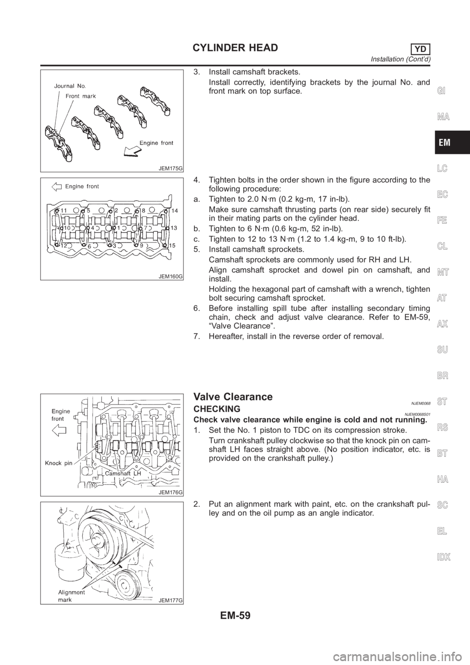
3. Remove front chain case.
Move power steering fluid reservoir tank from the bracket.
Loosen fixing bolts in the reverse order of that shown in the
figure and remove them.
Remove No. 6, 10, and 11 bolts with the rubber washer as
space is limited for pulling them out.
SEM514G
CAUTION:
While front chain case is removed, cover openings to pre-
vent entry of foreign material into engine.
Do not remove two mass dampers on the back of cover.
SEM515G
4. Set the No. 1 piston to TDC on its compression stroke.
Turn crankshaft pulley clockwise so that the alignment mark
(punched mark) on each camshaft sprocket is positioned as
shown in the figure.
No position indicator is provided on the crankshaft pulley.
When installing, color coded links on the secondary tim-
ing chain can be used as alignment marks. Marking may
not be necessary for removal; however, make alignment
marks as required because the alignment mark on fuel
injection pump sprocket may not be easy to see.
JEM124G
5. Remove chain tensioner.
a. Push the plunger of chain tensioner and keep it pressed with
a push pin.
JEM125G
b. Using a hexagon-head wrench (face to face: 5 mm, SST),
remove bolts to remove chain tensioner.
GI
MA
LC
EC
FE
CL
MT
AT
AX
SU
BR
ST
RS
BT
HA
SC
EL
IDX
TIMING CHAINYD
Secondary Timing Chain (Cont’d)
EM-21
Page 243 of 3189

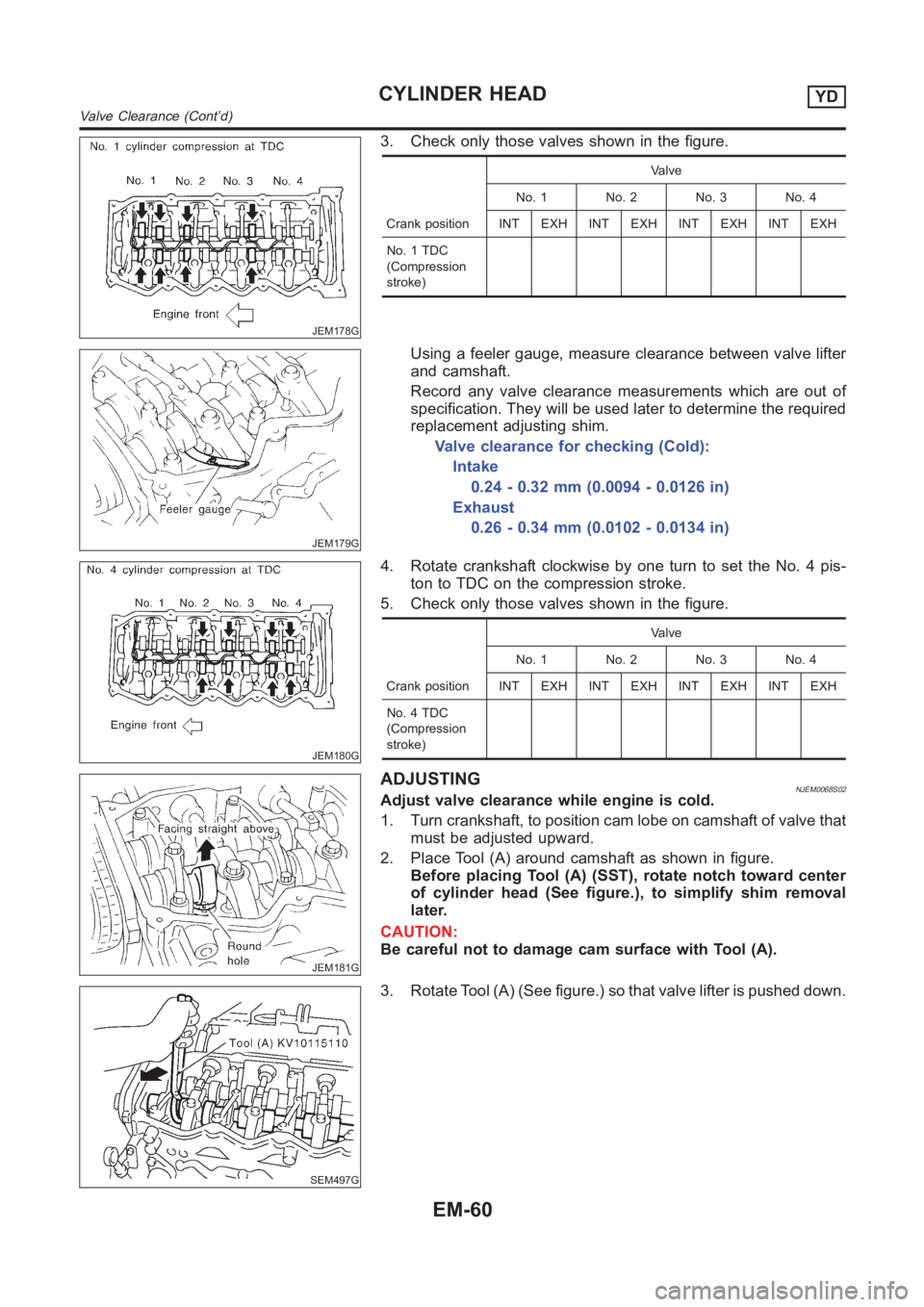
JEM175G
3. Install camshaft brackets.
Install correctly, identifying brackets by the journal No. and
front mark on top surface.
JEM160G
4. Tighten bolts in the order shown in the figure according to the
following procedure:
a. Tighten to 2.0 N·m (0.2 kg-m, 17 in-lb).
Make sure camshaft thrusting parts (on rear side) securely fit
in their mating parts on the cylinder head.
b. Tighten to 6 N·m (0.6 kg-m, 52 in-lb).
c. Tightento12to13N·m(1.2to1.4kg-m,9to10ft-lb).
5. Install camshaft sprockets.
Camshaft sprockets are commonly used for RH and LH.
Align camshaft sprocket and dowel pin on camshaft, and
install.
Holding the hexagonal part of camshaft with a wrench, tighten
bolt securing camshaft sprocket.
6. Before installing spill tube after installing secondary timing
chain, check and adjust valve clearance. Refer to EM-59,
“Valve Clearance”.
7. Hereafter, install in the reverse order of removal.
JEM176G
Valve ClearanceNJEM0068CHECKINGNJEM0068S01Check valve clearance while engine is cold and not running.
1. Set the No. 1 piston to TDC on its compression stroke.
Turn crankshaft pulley clockwise so that the knock pin on cam-
shaft LH faces straight above. (No position indicator, etc. is
provided on the crankshaft pulley.)
JEM177G
2. Put an alignment mark with paint, etc. on the crankshaft pul-
ley and on the oil pump as an angle indicator.
GI
MA
LC
EC
FE
CL
MT
AT
AX
SU
BR
ST
RS
BT
HA
SC
EL
IDX
CYLINDER HEADYD
Installation (Cont’d)
EM-59
Page 244 of 3189

JEM178G
3. Check only those valves shown in the figure.
Crank positionValve
No. 1 No. 2 No. 3 No. 4
INT EXH INT EXH INT EXH INT EXH
No. 1 TDC
(Compression
stroke)
JEM179G
Using a feeler gauge, measure clearance between valve lifter
and camshaft.
Record any valve clearance measurements which are out of
specification. They will be used later to determine the required
replacement adjusting shim.
Valve clearance for checking (Cold):
Intake
0.24 - 0.32 mm (0.0094 - 0.0126 in)
Exhaust
0.26 - 0.34 mm (0.0102 - 0.0134 in)
JEM180G
4. Rotate crankshaft clockwise by one turn to set the No. 4 pis-
ton to TDC on the compression stroke.
5. Check only those valves shown in the figure.
Crank positionValve
No. 1 No. 2 No. 3 No. 4
INT EXH INT EXH INT EXH INT EXH
No. 4 TDC
(Compression
stroke)
JEM181G
ADJUSTINGNJEM0068S02Adjust valve clearance while engine is cold.
1. Turn crankshaft, to position cam lobe on camshaft of valve that
must be adjusted upward.
2. Place Tool (A) around camshaft as shown in figure.
Before placing Tool (A) (SST), rotate notch toward center
of cylinder head (See figure.), to simplify shim removal
later.
CAUTION:
Be careful not to damage cam surface with Tool (A).
SEM497G
3. Rotate Tool (A) (See figure.) so that valve lifter is pushed down.
CYLINDER HEADYD
Valve Clearance (Cont’d)
EM-60
Page 381 of 3189
![NISSAN ALMERA N16 2003 Electronic Repair Manual ON BOARD DIAGNOSTIC (OBD) SYSTEM
EC-51
[QG (WITH EURO-OBD)]
C
D
E
F
G
H
I
J
K
L
MA
EC
HOW TO SWITCH DIAGNOSTIC TEST MODE
NOTE:
●It is better to count the time accurately with a clock.
●It is imp NISSAN ALMERA N16 2003 Electronic Repair Manual ON BOARD DIAGNOSTIC (OBD) SYSTEM
EC-51
[QG (WITH EURO-OBD)]
C
D
E
F
G
H
I
J
K
L
MA
EC
HOW TO SWITCH DIAGNOSTIC TEST MODE
NOTE:
●It is better to count the time accurately with a clock.
●It is imp](/manual-img/5/57350/w960_57350-380.png)
ON BOARD DIAGNOSTIC (OBD) SYSTEM
EC-51
[QG (WITH EURO-OBD)]
C
D
E
F
G
H
I
J
K
L
MA
EC
HOW TO SWITCH DIAGNOSTIC TEST MODE
NOTE:
●It is better to count the time accurately with a clock.
●It is impossible to switch the diagnostic mode when an accelerator pedal position sensor circuit
has a malfunction.
●Always ECM returns to Diagnostic Test Mode I after ignition switch is turned “OFF”.
How to Set Diagnostic Test Mode II (Self-diagnostic Results)
1. Confirm that accelerator pedal is fully released, turn ignition switch “ON” and wait 3 seconds.
2. Repeat the following procedure quickly five times within 5 seconds.
a. Fully depress the accelerator pedal.
b. Fully release the accelerator pedal.
3. Wait 7 seconds, fully depress the accelerator pedal and keep it for approx. 10 seconds until the MI starts
blinking.
4. Fully release the accelerator pedal.
ECM has entered to Diagnostic Test Mode II (Self-diagnostic results).
How to Set Diagnostic Test Mode II (Heated Oxygen Sensor 1 Monitor)
1. Set the ECM in Diagnostic Test Mode II (Self-diagnostic results). Refer to EC-51, "How to Set Diagnostic
Test Mode II (Self-diagnostic Results)" .
2. Start Engine.
ECM has entered to Diagnostic Test Mode II (Heated oxygen sensor 1 monitor).
How to Erase Diagnostic Test Mode II (Self-diagnostic Results)
1. Set ECM in Diagnostic Test Mode II (Self-diagnostic results). Refer to EC-51, "How to Set Diagnostic Test
Mode II (Self-diagnostic Results)" .
2. Fully depress the accelerator pedal and keep it for more than 10 seconds.
The emission-related diagnostic information has been erased from the backup memory in the ECM.
3. Fully release the accelerator pedal, and confirm the DTC 0000 is displayed.
DIAGNOSTIC TEST MODE I — BULB CHECK
In this mode, the MI on the instrument panel should stay ON. If it remains OFF, check the bulb. Refer to EL-
129 or see EC-397
.
DIAGNOSTIC TEST MODE I — MALFUNCTION WARNING
●These DTC numbers are clarified in Diagnostic Test Mode II (SELF-DIAGNOSTIC RESULTS)
DIAGNOSTIC TEST MODE II — SELF-DIAGNOSTIC RESULTS
In this mode, the DTC and 1st trip DTC are indicated by the number of blinks of the MI as shown below.
The DTC and 1st trip DTC are displayed at the same time. If the MI does not illuminate in diagnostic test mode
I (Malfunction warning), all displayed items are 1st trip DTCs. If only one code is displayed when the MI illumi-
nates in diagnostic test mode II (SELF-DIAGNOSTIC RESULTS), it is a DTC; if two or more codes are dis-
played, they may be either DTCs or 1st trip DTCs. DTC No. is same as that of 1st trip DTC. These unidentified
PBIB0092E
MI Condition
ON When the malfunction is detected.
OFF No malfunction.