2003 NISSAN ALMERA N16 EL-129
[x] Cancel search: EL-129Page 379 of 3189
![NISSAN ALMERA N16 2003 Electronic Repair Manual ON BOARD DIAGNOSTIC (OBD) SYSTEM
EC-49
[QG (WITH EURO-OBD)]
C
D
E
F
G
H
I
J
K
L
MA
EC
2. Perform “SELF-DIAGNOSTIC PROCEDURE (Without CONSULT-II)” in AT section titled “TROUBLE
DIAGNOSIS NISSAN ALMERA N16 2003 Electronic Repair Manual ON BOARD DIAGNOSTIC (OBD) SYSTEM
EC-49
[QG (WITH EURO-OBD)]
C
D
E
F
G
H
I
J
K
L
MA
EC
2. Perform “SELF-DIAGNOSTIC PROCEDURE (Without CONSULT-II)” in AT section titled “TROUBLE
DIAGNOSIS](/manual-img/5/57350/w960_57350-378.png)
ON BOARD DIAGNOSTIC (OBD) SYSTEM
EC-49
[QG (WITH EURO-OBD)]
C
D
E
F
G
H
I
J
K
L
MA
EC
2. Perform “SELF-DIAGNOSTIC PROCEDURE (Without CONSULT-II)” in AT section titled “TROUBLE
DIAGNOSIS”, “Self-diagnosis”. (The engine warm-up step can be skipped when performing the diagnosis
only to erase the DTC.)
3. Select Mode 4 with GST (Generic Scan Tool).
How to Erase DTC ( No Tools)
1. If the ignition switch stays “ON” after repair work, be sure to turn ignition switch OFF” once.
2. Wait at least 10 seconds and then turn it “ON” (engine stopped) again.
3. Change the diagnostic test mode from Mode II to Mode I by depressing the accelerator pedal. Refer to
EC-51, "
HOW TO SWITCH DIAGNOSTIC TEST MODE" .
●If the battery is disconnected, the emission-related diagnostic information will be lost after
approx. 24 hours.
●The following data are cleared when the ECM memory is erased.
–Diagnostic trouble codes
–1st trip diagnostic trouble codes
–Freeze frame data
–1st trip freeze frame data
–System readiness test (SRT) codes
–Test values
–Others
Actual work procedures are explained using a DTC as an example. Be careful so that not only the DTC, but all
of the data listed above, are cleared from the ECM memory during work procedures.
NATS (Nissan Anti-theft System)EBS00K3I
●If the security indicator lights up with the ignition switch in
the “ON” position or “NATS MALFUNCTION” is displayed
on “SELF-DIAG RESULTS” screen, perform self-diagnostic
results mode with CONSULT-II using NATS program card.
Refer to EL-386.
●Confirm no self-diagnostic results of NATS is displayed
before touching “ERASE” in “SELF-DIAG RESULTS” mode
with CONSULT-II.
●When replacing ECM, initialization of NATS system and reg-
istration of all NATS ignition key IDs must be carried out
with CONSULT-II using NATS program card.
Therefore, be sure to receive all keys from vehicle owner.
Regarding the procedures of NATS initialization and NATS ignition key ID registration, refer to
CONSULT-II operation manual, NATS.
Malfunction Indicator (MI)EBS00K3J
DESCRIPTION
The MI is located on the instrument panel.
1. The MI will light up when the ignition switch is turned ON without
the engine running. This is a bulb check.
●If the MI does not light up, refer to EL-129, or see EC-397 .
2. When the engine is started, the MI should go off.
If the MI remains on, the on board diagnostic system has
detected an engine system malfunction.
ON BOARD DIAGNOSTIC SYSTEM FUNCTION
The on board diagnostic system has the following four functions.
SEF515Y
SAT652J
Page 762 of 3189
![NISSAN ALMERA N16 2003 Electronic Repair Manual EC-432
[QG (WITHOUT EURO-OBD)]
ON BOARD DIAGNOSTIC (OBD) SYSTEM
Malfunction Indicator (MI)
EBS00KEQ
DESCRIPTION
The MI is located on the instrument panel.
1. The MI will light up when the ignition swi NISSAN ALMERA N16 2003 Electronic Repair Manual EC-432
[QG (WITHOUT EURO-OBD)]
ON BOARD DIAGNOSTIC (OBD) SYSTEM
Malfunction Indicator (MI)
EBS00KEQ
DESCRIPTION
The MI is located on the instrument panel.
1. The MI will light up when the ignition swi](/manual-img/5/57350/w960_57350-761.png)
EC-432
[QG (WITHOUT EURO-OBD)]
ON BOARD DIAGNOSTIC (OBD) SYSTEM
Malfunction Indicator (MI)
EBS00KEQ
DESCRIPTION
The MI is located on the instrument panel.
1. The MI will light up when the ignition switch is turned ON without
the engine running. This is a bulb check.
●If the MI does not light up, refer to EL-129, or see EC-715, "MI&
DATA LINK CONNECTORS" .
2. When the engine is started, the MI should go off.
If the MI remains on, the on board diagnostic system has
detected an engine system malfunction.
ON BOARD DIAGNOSTIC SYSTEM FUNCTION
The on board diagnostic system has the following four functions.
When there is an open circuit on MI circuit, the ECM cannot warn the driver by lighting MI up when there is
malfunction on engine control system.
Therefore, when electrical controlled throttle and part of ECM related diagnoses are continuously detected as
NG for 5 trips, ECM warns the driver that engine control system malfunctions and MI circuit is open by means
of operating fail-safe function.
The fail-safe function also operates when above diagnoses except MI circuit and demands the driver to repair
the malfunction.
SAT652J
Diagnostic Test
ModeKEY and ENG.
Sta tusFunction Explanation of Function
Mode I Ignition switch in
“ON” position
Engine stoppedBULB CHECK This function checks the MI bulb for damage (blown, open
circuit, etc.).
If the MI does not come on, check MI circuit.
Engine running MALFUNCTION
WARNINGThis is a usual driving condition. When a malfunction is
detected twice in two consecutive driving cycles (two trip
detection logic), the MI will light up to inform the driver that
a malfunction has been detected.
The following malfunctions will light up the MI in the 1st
trip.
●“One trip detection diagnoses”
Mode II Ignition switch in
“ON” position
Engine stoppedSELF-DIAGNOSTIC
RESULTSThis function allows DTCs and 1st trip DTCs to be read.
Engine running HEATED OXYGEN SENSOR 1
MONITORThis function allows the fuel mixture condition (lean or
rich), monitored by heated oxygen sensor 1, to be read.
Engine operating condition in fail-safe mode Engine speed will not rise more than 2,500 rpm due to the fuel cut
Page 1089 of 3189

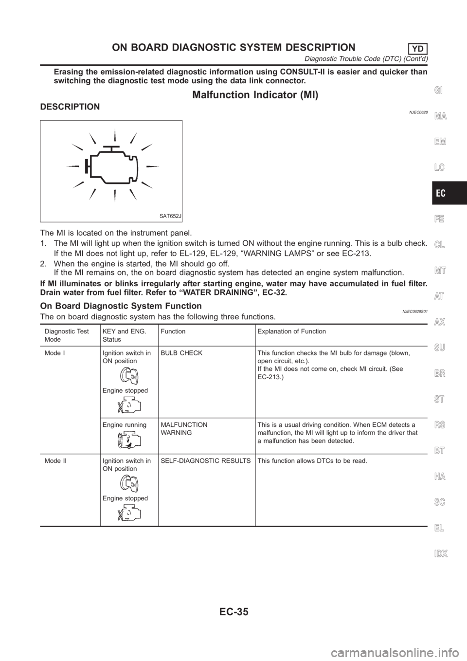
Erasing the emission-related diagnostic information using CONSULT-II is easier and quicker than
switching the diagnostic test mode using the data link connector.
Malfunction Indicator (MI)
DESCRIPTIONNJEC0628
SAT652J
The MI is located on the instrument panel.
1. The MI will light up when the ignition switch is turned ON without the engine running. This is a bulb check.
If the MI does not light up, refer to EL-129, EL-129, “WARNING LAMPS” or see EC-213.
2. When the engine is started, the MI should go off.
If the MI remains on, the on board diagnostic system has detected an engine system malfunction.
If MI illuminates or blinks irregularly after starting engine, water may have accumulated in fuel filter.
Drain water from fuel filter. Refer to “WATER DRAINING”, EC-32.
On Board Diagnostic System FunctionNJEC0628S01The on board diagnostic system has the following three functions.
Diagnostic Test
ModeKEY and ENG.
StatusFunction Explanation of Function
Mode I Ignition switch in
ON position
Engine stopped
BULB CHECK This function checks the MI bulb for damage (blown,
open circuit, etc.).
If the MI does not come on, check MI circuit. (See
EC-213.)
Engine running
MALFUNCTION
WARNINGThis is a usual driving condition. When ECM detects a
malfunction, the MI will light up to inform the driver that
a malfunction has been detected.
Mode II Ignition switch in
ON position
Engine stopped
SELF-DIAGNOSTIC RESULTS This function allows DTCs to be read.
GI
MA
EM
LC
FE
CL
MT
AT
AX
SU
BR
ST
RS
BT
HA
SC
EL
IDX
ON BOARD DIAGNOSTIC SYSTEM DESCRIPTIONYD
Diagnostic Trouble Code (DTC) (Cont’d)
EC-35
Page 1091 of 3189

Diagnostic Test Mode I — Bulb CheckNJEC0628S03In this mode, the MI on the instrument panel should stay ON. If it remains OFF, check the bulb. Refer to EL-129,
EL-129, “WARNING LAMPS” or see EC-213.
Diagnostic Test Mode I — Malfunction WarningNJEC0628S04
MI Condition
ON When the malfunction is detected or the ECM’s CPU is malfunctioning.
OFF No malfunction.
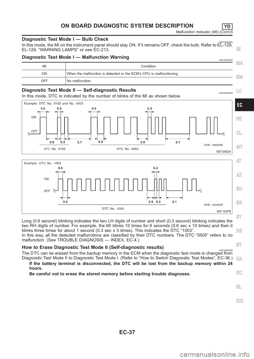
Diagnostic Test Mode II — Self-diagnostic ResultsNJEC0628S05In this mode, DTC is indicated by the number of blinks of the MI as shown below.
SEF298QA
SEF162PB
Long (0.6 second) blinking indicates the two LH digits of number and short (0.3 second) blinking indicates the
two RH digits of number. For example, the MI blinks 10 times for 6 seconds (0.6 sec x 10 times) and then it
blinks three times for about 1 second (0.3 sec x 3 times). This indicates theDTC “1003”.
In this way, all the detected malfunctions are classified by their DTC numbers. The DTC “0505” refers to no
malfunction. (See TROUBLE DIAGNOSIS — INDEX, EC-4.)
How to Erase Diagnostic Test Mode II (Self-diagnostic results)NJEC0628S06The DTC can be erased from the backup memory in the ECM when the diagnostic test mode is changed from
Diagnostic Test Mode II to Diagnostic Test Mode I. (Refer to “How to Switch Diagnostic Test Modes”, EC-36.)
If the battery terminal is disconnected, the DTC will be lost from the backup memory within 24
hours.
Be careful not to erase the stored memory before starting trouble diagnoses.
GI
MA
EM
LC
FE
CL
MT
AT
AX
SU
BR
ST
RS
BT
HA
SC
EL
IDX
ON BOARD DIAGNOSTIC SYSTEM DESCRIPTIONYD
Malfunction Indicator (MI) (Cont’d)
EC-37
Page 2465 of 3189

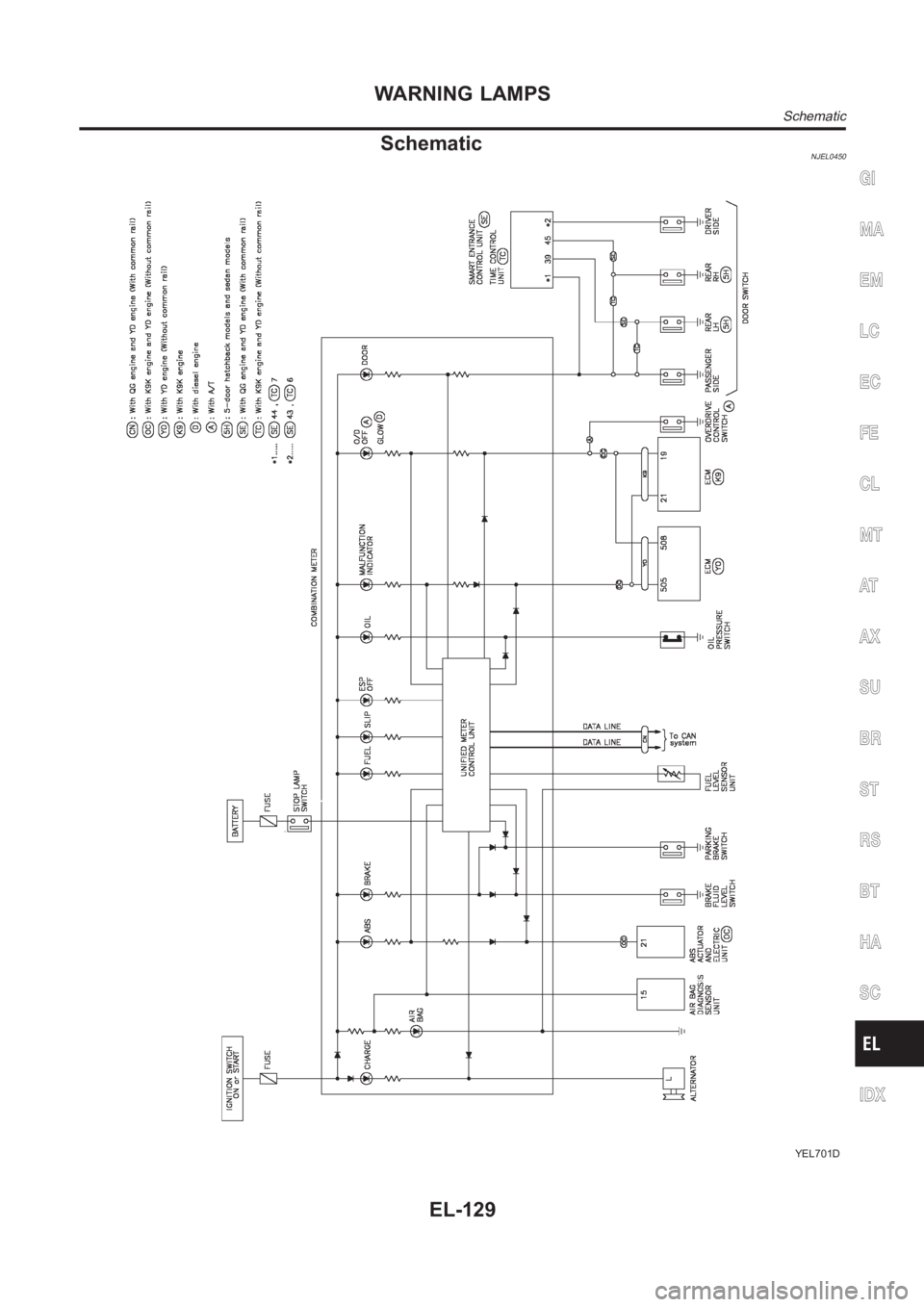
SchematicNJEL0450
YEL701D
GI
MA
EM
LC
EC
FE
CL
MT
AT
AX
SU
BR
ST
RS
BT
HA
SC
IDX
WARNING LAMPS
Schematic
EL-129
Page 3183 of 3189

Starting system...............................................SC-13
Steering linkage ..............................................ST-15
Steering switch................................................EL-41
Steering wheel and column ............................ST-10
Steering wheel play ..........................................ST-6
Steering wheel turning force .............................ST-8
Stop lamp switch (QG engine) ......EC-361, EC-630
Stop lamp <0011001100110011001100110011001100110011001100110011001100110011001100110011001100110011001100110011001100110011001100110011001100110011001100110011001100110011001100110011001100110011001100110011001100
110011001100110011[.EL-58
STOP/L - Wiring diagram................................EL-58
Striking rod (M/T) ...............................MT-32, 56, 94
Strut (front) <0011001100110011001100110011001100110011001100110011001100110011001100110011001100110011001100110011001100110011001100110011001100110011001100110011001100110011001100110011001100110011001100110011001100
11[....SU-9
Strut (rear) <0011001100110011001100110011001100110011001100110011001100110011001100110011001100110011001100110011001100110011001100110011001100110011001100110011001100110011001100110011001100110011001100110011001100
110011[..SU-20
Sub-gear (M/T) .........................................MT-31, 55
Sun roof, electric ...........................................EL-249
Sunload sensor...........ATC-106, ATC-108, ATC-118
Sunroof<0011001100110011001100110011001100110011001100110011001100110011001100110011001100110011001100110011001100110011001100110011001100110011001100110011001100110011001100110011001100110011001100110011001100
1100110011001100110011[....BT-60
Super lock <0011001100110011001100110011001100110011001100110011001100110011001100110011001100110011001100110011001100110011001100110011001100110011001100110011001100110011001100110011001100110011001100110011001100
11001100110028[L-301
Supplemental restraint system - Wiring
diagram <0011001100110011001100110011001100110011001100110011001100110011001100110011001100110011001100110011001100110011001100110011001100110011001100110011001100110011001100110011001100110011001100110011001100
1100110011001100110035[S-46
Supplemental Restraint System .....................RS-20
Symbols and abbreviations..............................GI-11
Symptom matrix chart
(QG engine)..................................EC-70, EC-449
Symptom matrix chart (YD engine)................EC-53
Synchronizer (M/T) ............................MT-31, 55, 93
System readiness test (SRT) code
(QG engine) ................................................EC-40
T
Tachometer <0011001100110011001100110011001100110011001100110011001100110011001100110011001100110011001100110011001100110011001100110011001100110011001100110011001100110011001100110011001100110011001100110011001100
1100110028[L-110
Tail lamp <0011001100110011001100110011001100110011001100110011001100110011001100110011001100110011001100110011001100110011001100110011001100110011001100110011001100110011001100110011001100110011001100110011001100
110011001100110011[...EL-55
TCM circuit diagram ........................................AT-15
TCM inspection table .......................AT-107, AT-303
Thermostat................................................LC-15,40
Three way catalyst function
(QG engine) ..............................................EC-247
Three way catalyst precautions.........................GI-6
Throttle body (QG engine) .............................EM-18
Throttle control motor relay
(QG engine)................................EC-286, EC-587
Throttle position sensor (TPS)
(QG engine) ..EC-200, EC-206, EC-336, EC-342,
EC-344, EC-526, EC-532, EC-609,
EC-615, EC-617
Throttle position switch ....................AT-244, AT-340
Throttle valve closed position learning
(QG engine)..................................EC-31, EC-426
Throwout bearing - See Clutch release
bearing ..................................................CL-17,20
Tie-rod ball joints.............................................ST- 1 9
Tie-rod <0011001100110011001100110011001100110011001100110011001100110011001100110011001100110011001100110011001100110011001100110011001100110011001100110011001100110011001100110011001100110011001100110011001100
1100110011001100110011[.....ST-15
Tightening torque of standard bolts.................GI-50
Timing chain (QG engine)..............................EM-47
Timing chain (YD engine) ..............................EM-20
Tire size <0011001100110011001100110011001100110011001100110011001100110011001100110011001100110011001100110011001100110011001100110011001100110011001100110011001100110011001100110011001100110011001100110011001100
110011001100110011[....GI-44
Torque converter installation ............AT-412, AT-509
Tow truck towing ..............................................GI-48
TPS1 - Wiring diagram
(QG engine)................................EC-208, EC-534TPS2 - Wiring diagram
(QG engine) ................................EC-338, EC-611
TPS3 - Wiring diagram
(QG engine)................................EC-202, EC-528
Transmission case (M/T) ...................MT-30, 54, 92
Tread-FR&RR (Dimensions)............................GI-44
Trim <0011001100110011001100110011001100110011001100110011001100110011001100110011001100110011001100110011001100110011001100110011001100110011001100110011001100110011001100110011001100110011001100110011001100
1100110011001100110011001100110011[......BT-31
Trouble diagnoses ...........................................GI-32
Trunk lid finisher..............................................BT- 4 5
Trunk lid opener - See Trunk lid .....................BT-10
Trunk lid trim <0011001100110011001100110011001100110011001100110011001100110011001100110011001100110011001100110011001100110011001100110011001100110011001100110011001100110011001100110011001100110011001100110011001100
11[BT-45
Trunk lid <0011001100110011001100110011001100110011001100110011001100110011001100110011001100110011001100110011001100110011001100110011001100110011001100110011001100110011001100110011001100110011001100110011001100
110011001100110011[...BT-10
Trunk room lamp ...........................................EL-108
Trunk room trim...............................................BT-45
TURN - Wiring diagram ..................................EL-71
Turn signal lamp .............................................EL-67
Two trip detection logic
(QG engine)..................................EC-36, EC-430
Two-pole lift <0011001100110011001100110011001100110011001100110011001100110011001100110011001100110011001100110011001100110011001100110011001100110011001100110011001100110011001100110011001100110011001100110011001100
11[..GI-47
U
Under body <0011001100110011001100110011001100110011001100110011001100110011001100110011001100110011001100110011001100110011001100110011001100110011001100110011001100110011001100110011001100110011001100110011001100
11001100110025[T- 7 7
V
Vacuum hose (brake system).........................BR-22
Vacuum hose drawing (Engine control)
(QG engine)..................................EC-22, EC-417
Vacuum pump.................................................BR-23
Valve clearance (YD engine) .........................EM-59
Valve guide (QG engine) ...............................EM-63
Valve guide (YD engine) ................................EM-50
Valve lifter<0011001100110011001100110011001100110011001100110011001100110011001100110011001100110011001100110011001100110011001100110011001100110011001100110011001100110011001100110011001100110011001100110011001100
110011[...EM-41
Valve seat (QG engine) .................................EM-64
Valve seat (YD engine) ..................................EM-52
Valve spring (QG engine) ..............................EM-66
Valve spring (YD engine) ...............................EM-54
Vehicle speed sensor (VSS)
(QG engine)................................EC-258, EC-679
Vehicle speed sensor (VSS)
(YD engine)...............................................EC-105
Ventilation air filter (manual A/C) ...................HA-95
Ventilation air filter ......................................ATC-129
Viscosity number (SAE) .................................MA-20
Viscous coupling (FF M/T) .............................MT-93
VSS - Wiring diagram (YD engine) ..............EC-105
W
WARN - Wiring diagram ...............................EL-130
Warning chime ..............................................EL-136
Warning lamps ..............................................EL-129
Washer, front .................................................EL-158
Water pump ..............................................LC-14, 38
Water temperature gauge .............................EL-110
Weatherstrip - See Exterior ............................BT-47
GI
MA
EM
LC
EC
FE
CL
MT
AT
AX
SU
BR
ST
RS
BT
HA
SC
EL
ALPHABETICAL INDEX
IDX-9