2003 NISSAN ALMERA N16 battery location
[x] Cancel search: battery locationPage 7 of 3189
SEF289H
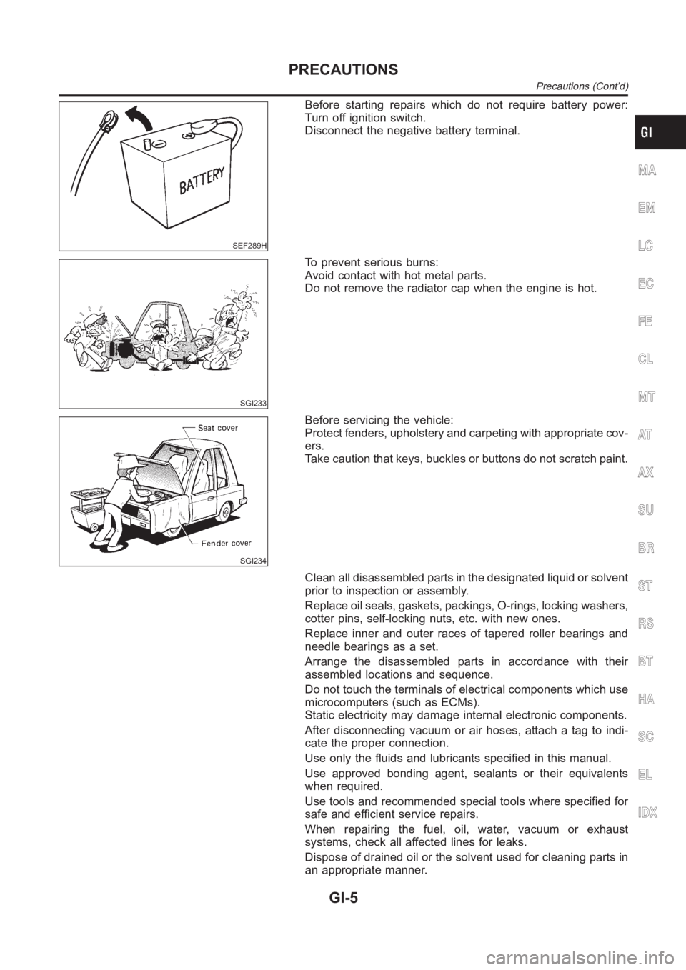
Before starting repairs which do not require battery power:
Turn off ignition switch.
Disconnect the negative battery terminal.
SGI233
To prevent serious burns:
Avoid contact with hot metal parts.
Do not remove the radiator cap when the engine is hot.
SGI234
Before servicing the vehicle:
Protect fenders, upholstery and carpeting with appropriate cov-
ers.
Take caution that keys, buckles or buttons do not scratch paint.
Clean all disassembled parts in the designated liquid or solvent
prior to inspection or assembly.
Replace oil seals, gaskets, packings, O-rings, locking washers,
cotter pins, self-locking nuts, etc. with new ones.
Replace inner and outer races of tapered roller bearings and
needle bearings as a set.
Arrange the disassembled parts in accordance with their
assembled locations and sequence.
Do not touch the terminals of electrical components which use
microcomputers (such as ECMs).
Static electricity may damage internal electronic components.
After disconnecting vacuum or air hoses, attach a tag to indi-
cate the proper connection.
Use only the fluids and lubricants specified in this manual.
Use approved bonding agent, sealants or their equivalents
when required.
Use tools and recommended special tools where specified for
safe and efficient service repairs.
When repairing the fuel, oil, water, vacuum or exhaust
systems, check all affected lines for leaks.
Dispose of drained oil or the solvent used for cleaning parts in
an appropriate manner.
MA
EM
LC
EC
FE
CL
MT
AT
AX
SU
BR
ST
RS
BT
HA
SC
EL
IDX
PRECAUTIONS
Precautions (Cont’d)
GI-5
Page 16 of 3189
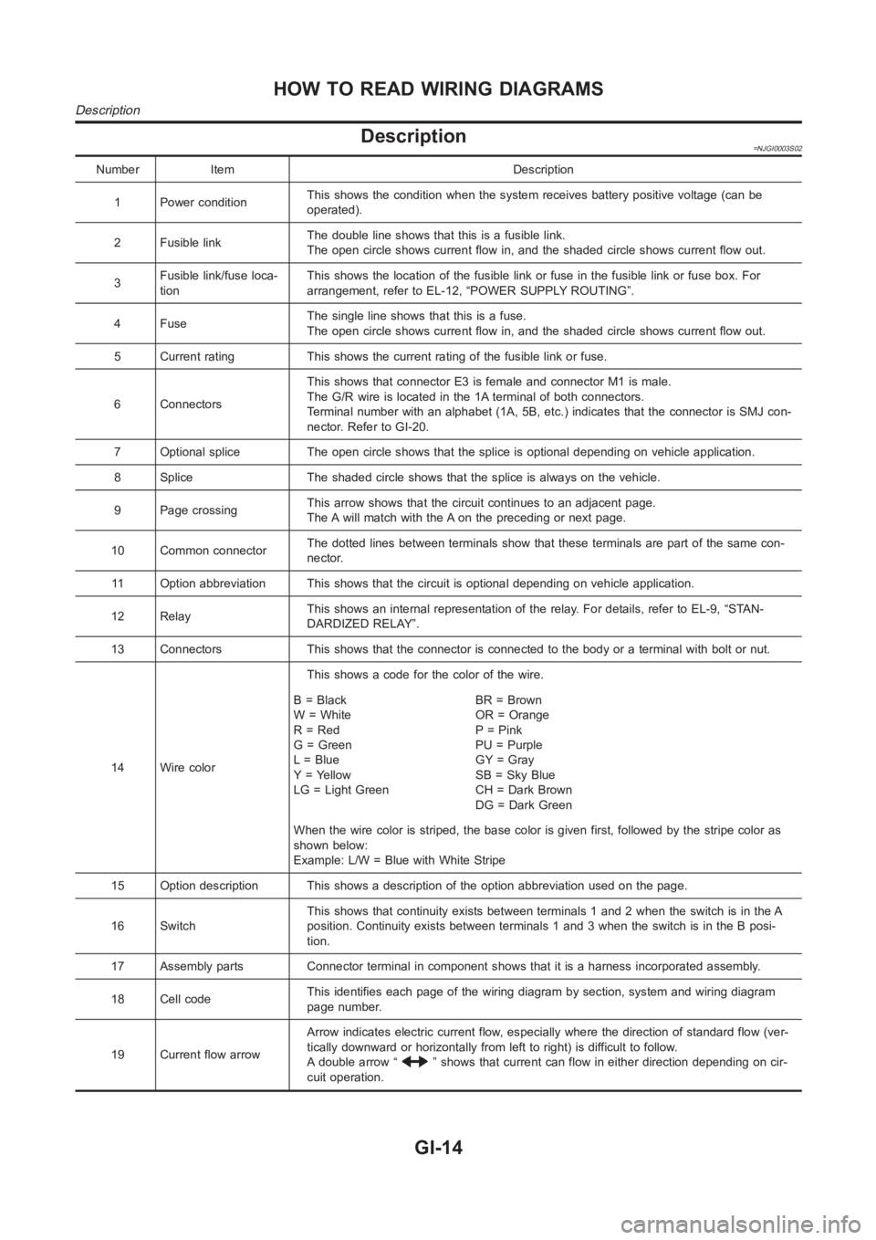
Description=NJGI0003S02
Number Item Description
1 Power conditionThis shows the condition when the system receives battery positive voltage (can be
operated).
2 Fusible linkThe double line shows that this is a fusible link.
The open circle shows current flow in, and the shaded circle shows current flow out.
3Fusible link/fuse loca-
tionThis shows the location of the fusible link or fuse in the fusible link or fusebox.For
arrangement, refer to EL-12, “POWER SUPPLY ROUTING”.
4FuseThe single line shows that this is a fuse.
The open circle shows current flow in, and the shaded circle shows current flow out.
5 Current rating This shows the current rating of the fusible link or fuse.
6 ConnectorsThis shows that connector E3 is female and connector M1 is male.
The G/R wire is located in the 1A terminal of both connectors.
Terminal number with an alphabet (1A, 5B, etc.) indicates that the connector is SMJ con-
nector. Refer to GI-20.
7 Optional splice The open circle shows that the splice is optional depending on vehicle application.
8 Splice The shaded circle shows that the splice is always on the vehicle.
9 Page crossingThis arrow shows that the circuit continues to an adjacent page.
The A will match with the A on the preceding or next page.
10 Common connectorThe dotted lines between terminals show that these terminals are part of thesamecon-
nector.
11 Option abbreviation This shows that the circuit is optional depending on vehicle application.
12 RelayThis shows an internal representation of the relay. For details, refer to EL-9, “STAN-
DARDIZED RELAY”.
13 Connectors This shows that the connector is connected to the body or a terminal with bolt or nut.
14 Wire colorThis shows a code for the color of the wire.
B=Black
W = White
R = Red
G = Green
L = Blue
Y = Yellow
LG = Light GreenBR = Brown
OR = Orange
P = Pink
PU = Purple
GY = Gray
SB = Sky Blue
CH = Dark Brown
DG=DarkGreen
When the wire color is striped, the base color is given first, followed by the stripe color as
shown below:
Example: L/W = Blue with White Stripe
15 Option description This shows a description of the option abbreviationused on the page.
16 SwitchThis shows that continuity exists between terminals 1 and 2 when the switchis in the A
position. Continuity exists between terminals 1 and 3 when the switch is inthe B posi-
tion.
17 Assembly parts Connector terminal in component shows that it is a harness incorporated assembly.
18 Cell codeThis identifies each page of the wiring diagram by section, system and wiring diagram
page number.
19 Current flow arrowArrow indicates electric current flow, especially where the direction ofstandard flow (ver-
tically downward or horizontally from left to right) is difficult to follow.
A double arrow “
” shows that current can flow in either direction depending on cir-
cuit operation.
HOW TO READ WIRING DIAGRAMS
Description
GI-14
Page 34 of 3189
NJGI0006
NOTICE:
Trouble diagnoses indicate work procedures required to diagnose
problems effectively. Observe the following instructions before
diagnosing.
1)Before performing trouble diagnoses, read the “Prelimi-
nary Check”, the “Symptom Chart” or the “Work Flow”.
2)After repairs, re-check that the problem has been com-
pletely eliminated.
3)Refer to Component Parts and Harness Connector Loca-
tion for the Systems described in each section for
identification/location of components and harness con-
nectors.
4)Refer to the Circuit Diagram for quick pinpoint check.
If you need to check circuit continuity between harness
connectors in more detail, such as when a sub-harness is
used, refer to Wiring Diagram in each individual section
and Harness Layout in EL section for identification of har-
ness connectors.
5)When checking circuit continuity, ignition switch should
be OFF.
6)Before checking voltage at connectors, check battery volt-
age.
7)After accomplishing the Diagnostic Procedures and Elec-
trical Components Inspection, make sure that all harness
connectors are reconnected as they were.
HOW TO FOLLOW TROUBLE DIAGNOSES
GI-32
Page 450 of 3189
![NISSAN ALMERA N16 2003 Electronic Repair Manual EC-120
[QG (WITH EURO-OBD)]
DTC P0011 IVT CONTROL
On Board Diagnosis Logic
EBS00K4E
The MI will not light up for this diagnosis.
FAIL-SAFE MODE
When the malfunction is detected, the ECM enters fail-sa NISSAN ALMERA N16 2003 Electronic Repair Manual EC-120
[QG (WITH EURO-OBD)]
DTC P0011 IVT CONTROL
On Board Diagnosis Logic
EBS00K4E
The MI will not light up for this diagnosis.
FAIL-SAFE MODE
When the malfunction is detected, the ECM enters fail-sa](/manual-img/5/57350/w960_57350-449.png)
EC-120
[QG (WITH EURO-OBD)]
DTC P0011 IVT CONTROL
On Board Diagnosis Logic
EBS00K4E
The MI will not light up for this diagnosis.
FAIL-SAFE MODE
When the malfunction is detected, the ECM enters fail-safe mode.
DTC Confirmation ProcedureEBS00K4F
CAUTION:
Always drive at a safe speed.
NOTE:
●If DTC P0011 is displayed with DTC P1111, first perform trouble diagnosis for “DTC P1111”. See
EC-272, "
DTC P1111 IVT CONTROL SOLENOID VALVE" .
●If “DTC Confirmation Procedure” has been previously conducted, always turn ignition switch “OFF” and
wait at least 10 seconds before conducting the next test.
TESTING CONDITION:
Before performing the following procedure, confirm that battery voltage is between 10V and 16V at
idle.
WITH CONSULT-II
1. Turn ignition switch “ON” and select ″DATA MONITOR″ mode
with CONSULT-II.
2. Start engine and warm it up to the normal operating tempera-
ture.
3. Maintain the following conditions for at least 20 consecutive sec-
onds.
4. Stop vehicle with engine running and let engine idle for 10 seconds.
5. If 1st trip DTC is detected, go to EC-121, "
Diagnostic Procedure" .
If 1st trip DTC is not detected, go to next step.
6. Maintain the following conditions for at least 10 consecutive seconds.
7. If 1st trip DTC is detected, go to EC-121, "
Diagnostic Procedure" .
DTC No. Trouble diagnosis name Detecting condition Possible cause
P0011
0011Intake valve timing con-
trol performanceThere is a gap between angle of target and
phase-control angle degree.
●Crankshaft position sensor (POS)
●Camshaft position sensor (PHASE)
●Accumulation of debris to the signal pick-up
portion of the camshaft
Detected items Engine operating condition in fail-safe mode
Intake valve timing control The signal is not energized to the solenoid valve and the valve control does not function
VHCL SPEED SE 100 - 120 km/h (63 - 75 MPH)
ENG SPEED 2,000 - 4,000 rpm
COOLANT TEMPS 60 - 120°C (140 - 248°F)
B/FUEL SCHDL More than 3.38 msec
Selector leverA/T models: D position
M/T models: 5th position
ENG SPEED 1,700 - 3,175 rpm (A constant rotation is maintained.)
COOLANT TEMPS 70 - 105°C (176 - 194°F)
Selector lever 1st or 2nd position
Driving location uphillDriving vehicle uphill
(Increased engine load will help maintain the driving
conditions required for this test.)
SEF174Y
Page 1129 of 3189
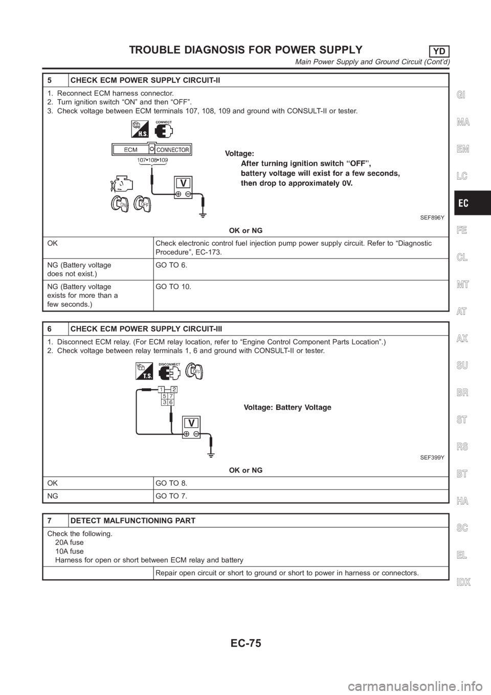
5 CHECK ECM POWER SUPPLY CIRCUIT-II
1. Reconnect ECM harness connector.
2. Turn ignition switch “ON” and then “OFF”.
3. Check voltage between ECM terminals 107, 108, 109 and ground with CONSULT-II or tester.
SEF896Y
OK or NG
OK Check electronic control fuel injection pump power supply circuit. Refer to “Diagnostic
Procedure”, EC-173.
NG (Battery voltage
does not exist.)GO TO 6.
NG (Battery voltage
exists for more than a
few seconds.)GO TO 10.
6 CHECK ECM POWER SUPPLY CIRCUIT-III
1. Disconnect ECM relay. (For ECM relay location, refer to “Engine ControlComponent Parts Location”.)
2. Check voltage between relay terminals 1, 6 and ground with CONSULT-II ortester.
SEF399Y
OK or NG
OK GO TO 8.
NG GO TO 7.
7 DETECT MALFUNCTIONING PART
Check the following.
20A fuse
10A fuse
Harness for open or short between ECM relay and battery
Repair open circuit or short to ground or short to power in harness or connectors.
GI
MA
EM
LC
FE
CL
MT
AT
AX
SU
BR
ST
RS
BT
HA
SC
EL
IDX
TROUBLE DIAGNOSIS FOR POWER SUPPLYYD
Main Power Supply and Ground Circuit (Cont’d)
EC-75
Page 1233 of 3189
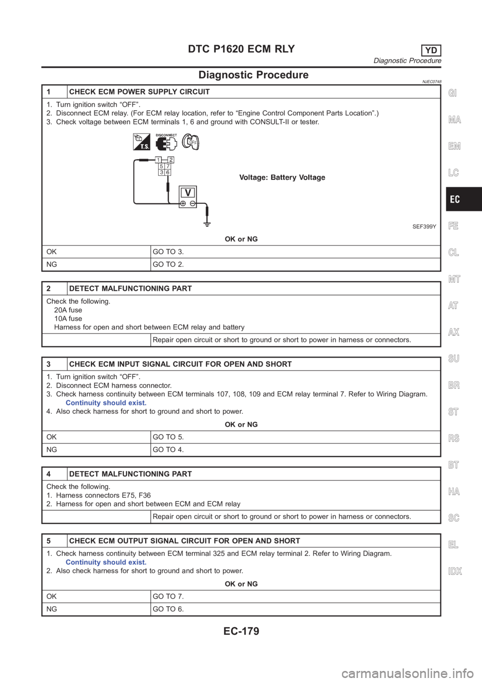
Diagnostic ProcedureNJEC0748
1 CHECK ECM POWER SUPPLY CIRCUIT
1. Turn ignition switch “OFF”.
2. Disconnect ECM relay. (For ECM relay location, refer to “Engine ControlComponent Parts Location”.)
3. Check voltage between ECM terminals 1, 6 and ground with CONSULT-II or tester.
SEF399Y
OK or NG
OK GO TO 3.
NG GO TO 2.
2 DETECT MALFUNCTIONING PART
Check the following.
20A fuse
10A fuse
Harness for open and short between ECM relay and battery
Repair open circuit or short to ground or short to power in harness or connectors.
3 CHECK ECM INPUT SIGNAL CIRCUIT FOR OPEN AND SHORT
1. Turn ignition switch “OFF”.
2. Disconnect ECM harness connector.
3. Check harness continuity between ECM terminals 107, 108, 109 and ECM relay terminal 7. Refer to Wiring Diagram.
Continuity should exist.
4. Also check harness for short to ground and short to power.
OK or NG
OK GO TO 5.
NG GO TO 4.
4 DETECT MALFUNCTIONING PART
Check the following.
1. Harness connectors E75, F36
2. Harness for open and short between ECM and ECM relay
Repair open circuit or short to ground or short to power in harness or connectors.
5 CHECK ECM OUTPUT SIGNAL CIRCUIT FOR OPEN AND SHORT
1. Check harness continuity between ECM terminal 325 and ECM relay terminal 2. Refer to Wiring Diagram.
Continuity should exist.
2. Also check harness for short to ground and short to power.
OK or NG
OK GO TO 7.
NG GO TO 6.
GI
MA
EM
LC
FE
CL
MT
AT
AX
SU
BR
ST
RS
BT
HA
SC
EL
IDX
DTC P1620 ECM RLYYD
Diagnostic Procedure
EC-179
Page 1255 of 3189
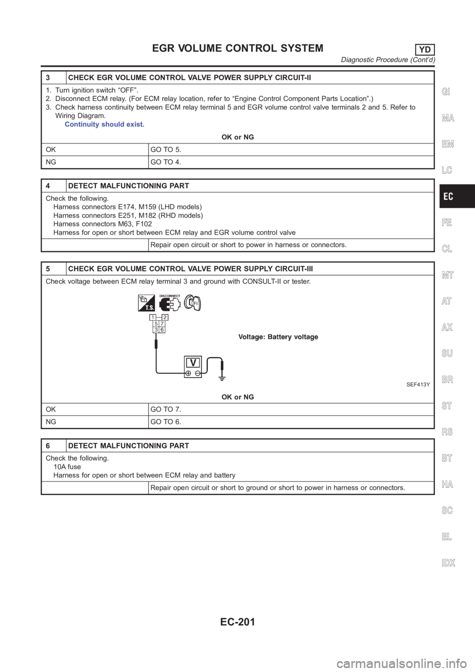
3 CHECK EGR VOLUME CONTROL VALVE POWER SUPPLY CIRCUIT-II
1. Turn ignition switch “OFF”.
2. Disconnect ECM relay. (For ECM relay location, refer to “Engine ControlComponent Parts Location”.)
3. Check harness continuity between ECM relay terminal 5 and EGR volume control valve terminals 2 and 5. Refer to
Wiring Diagram.
Continuity should exist.
OK or NG
OK GO TO 5.
NG GO TO 4.
4 DETECT MALFUNCTIONING PART
Check the following.
Harness connectors E174, M159 (LHD models)
Harness connectors E251, M182 (RHD models)
Harness connectors M63, F102
Harness for open or short between ECM relay and EGR volume control valve
Repair open circuit or short to power in harness or connectors.
5 CHECK EGR VOLUME CONTROL VALVE POWER SUPPLY CIRCUIT-III
Check voltage between ECM relay terminal 3 and ground with CONSULT-II or tester.
SEF413Y
OK or NG
OK GO TO 7.
NG GO TO 6.
6 DETECT MALFUNCTIONING PART
Check the following.
10A fuse
Harness for open or short between ECM relay and battery
Repair open circuit or short to ground or short to power in harness or connectors.
GI
MA
EM
LC
FE
CL
MT
AT
AX
SU
BR
ST
RS
BT
HA
SC
EL
IDX
EGR VOLUME CONTROL SYSTEMYD
Diagnostic Procedure (Cont’d)
EC-201
Page 2339 of 3189
Trouble Diagnoses/YD Engine Models with
Common Rail and K9K Engine Models...................292
POWER DOOR LOCK - SUPER LOCK -...................301
System Description ..................................................301
Schematic <0011001100110011001100110011001100110011001100110011001100110011001100110011001100110011001100110011001100110011001100110011001100110011001100110011001100110011001100110011001100110011001100110011001100
11001100110011[..........304
Wiring Diagram - S/LOCK - .....................................306
Trouble Diagnosis/QG and YD Engine Models
with Common Rail ...................................................313
Trouble Diagnoses/YD Engine Models without
Common Rail and K9K Engine Models...................339
MULTI-REMOTE CONTROL SYSTEM.......................352
System Description ..................................................352
Wiring Diagram - MULTI - .......................................353
Trouble Diagnoses/QG and YD Engine Models
with Common Rail ...................................................355
Trouble Diagnoses/YD Engine Models without
Common Rail and K9K Engine Models...................360
ID Code Entry Procedure ........................................364
Remote Controller Battery Replacement.................365
THEFT WARNING SYSTEM.......................................366
Wiring Diagram - PRWIRE -....................................366
SMART ENTRANCE CONTROL SYSTEM.................368
Description <0011001100110011001100110011001100110011001100110011001100110011001100110011001100110011001100110011001100110011001100110011001100110011001100110011001100110011001100110011001100110011001100110011001100
110011[...........368
CONSULT-II <0011001100110011001100110011001100110011001100110011001100110011001100110011001100110011001100110011001100110011001100110011001100110011001100110011001100110011001100110011001100110011001100110011001100
1100110011[........369
Schematic <0011001100110011001100110011001100110011001100110011001100110011001100110011001100110011001100110011001100110011001100110011001100110011001100110011001100110011001100110011001100110011001100110011001100
11001100110011[..........374
Smart Entrance Control Unit Inspection Table ........376
Trouble Diagnoses...................................................378
Power Supply and Ground Circuit Check ...............379
CAN Communication Line Check ............................380
TIME CONTROL UNIT................................................381
Description <0011001100110011001100110011001100110011001100110011001100110011001100110011001100110011001100110011001100110011001100110011001100110011001100110011001100110011001100110011001100110011001100110011001100
110011[...........381
Trouble Diagnoses...................................................382
Schematic <0011001100110011001100110011001100110011001100110011001100110011001100110011001100110011001100110011001100110011001100110011001100110011001100110011001100110011001100110011001100110011001100110011001100
11001100110011[..........384
NATS (NISSAN ANTI-THEFT SYSTEM).....................386
Component Parts and Harness Connetor
Location <0011001100110011001100110011001100110011001100110011001100110011001100110011001100110011001100110011001100110011001100110011001100110011001100110011001100110011001100110011001100110011001100110011001100
110011001100110011[............386
System Description ..................................................386
System Composition ................................................387
Wiring Diagram - NATS -.........................................388
CONSULT-II <0011001100110011001100110011001100110011001100110011001100110011001100110011001100110011001100110011001100110011001100110011001100110011001100110011001100110011001100110011001100110011001100110011001100
1100110011[........390
Trouble Diagnoses/QG and YD Engine Models
with Common Rail ...................................................393
How to Replace NATS Antenna Amp ...................... 411
Trouble Diagnoses/YD Engine Models without
Common Rail and K9K Engine Models...................412
How to Replace NATS IMMU ..................................429
NAVIGATION SYSTEM...............................................430
System Description ..................................................430
Precautions for AV and NAVI Control Unit
Replacement <0011001100110011001100110011001100110011001100110011001100110011001100110011001100110011001100110011001100110011001100110011001100110011001100110011001100110011001100110011001100110011001100110011001100
110011[........440
Component Parts Location ......................................441
Location of Antenna .................................................441Schematic <0011001100110011001100110011001100110011001100110011001100110011001100110011001100110011001100110011001100110011001100110011001100110011001100110011001100110011001100110011001100110011001100110011001100
11001100110011[..........442
Wiring Diagram - NAVI - ..........................................443
Wiring Diagram - COMM -.......................................448
Terminals and Reference Value for AV and NAVI
Control Unit <0011001100110011001100110011001100110011001100110011001100110011001100110011001100110011001100110011001100110011001100110011001100110011001100110011001100110011001100110011001100110011001100110011001100
110011[..........450
Terminals and Reference Value for Display Unit ....454
Terminals and Reference Value for Multifunction
Switch <0011001100110011001100110011001100110011001100110011001100110011001100110011001100110011001100110011001100110011001100110011001100110011001100110011001100110011001100110011001100110011001100110011001100
11001100110011001100110011[.............456
Self-Diagnosis Function ...........................................457
Self-Diagnosis Mode................................................458
Confirmation/Adjustment Mode ...............................461
Power Supply and Ground Circuit Check ...............467
Check Display Unit, Multifunction Switch Power,
and Ground Circuit ..................................................469
Vehicle Speed Signal Check ...................................471
Illumination Control Signal Check ...........................472
Ignition Signal Check ...............................................473
Reverse Signal Check .............................................474
RGB Screen Is Not Shown......................................475
No Screens Appear .................................................477
Color of RGB Image Is Not Proper .........................477
RGB Screen Is Rolling ............................................482
Guide Sound Is Not Heard ......................................484
Multifunction Switch Controls Are Ineffective
(Rear Defogger Control Excluded) ..........................485
Air Conditioning Controls (Only) Are Ineffective
(Rear Defogger Control Excluded) ..........................489
Rear Defogger Does Not Operate...........................491
Rear Defogger Indicator Lamp Does Not
Illuminate<0011001100110011001100110011001100110011001100110011001100110011001100110011001100110011001100110011001100110011001100110011001100110011001100110011001100110011001100110011001100110011001100110011001100
1100110011[.............492
No Fuel Information Is Displayed/No Warning
Message Is Displayed .............................................493
Previous Conditions Are Not Stored........................495
The Position of The Current-Location Mark Is
Not Correct <0011001100110011001100110011001100110011001100110011001100110011001100110011001100110011001100110011001100110011001100110011001100110011001100110011001100110011001100110011001100110011001100110011001100
1100110011[.........495
Radio Wave From The GPS Satellite Is Not
Received <0011001100110011001100110011001100110011001100110011001100110011001100110011001100110011001100110011001100110011001100110011001100110011001100110011001100110011001100110011001100110011001100110011001100
110011001100110011[...........495
Display Does Not Change When Screen
Adjustment Is Performed .........................................496
Day/Night Display Switching Is Not Done. Night
Illumination for AV and NAVI Control Unit Does
Not Illuminate ...........................................................496
On Multifunction Switch, a Specific Switch Does
Not Operate in All Conditions ..................................496
Driving Information Is Inaccurate. Maintenance
Information Is Inaccurate .........................................496
System Does Not Start ............................................497
The Current Position Mark Is in the Wrong Place ..497
The Current-Location Mark Will Not Move
Forward/Backward ...................................................498
The Position of the Current-Location Mark Is Not
Correct <0011001100110011001100110011001100110011001100110011001100110011001100110011001100110011001100110011001100110011001100110011001100110011001100110011001100110011001100110011001100110011001100110011001100
1100110011001100110011[.............498
GI
MA
EM
LC
EC
FE
CL
MT
AT
AX
SU
BR
ST
RS
BT
HA
SC
IDX
CONTENTS(Cont’d)
EL-3