2003 NISSAN ALMERA N16 junction box b4
[x] Cancel search: junction box b4Page 17 of 3189
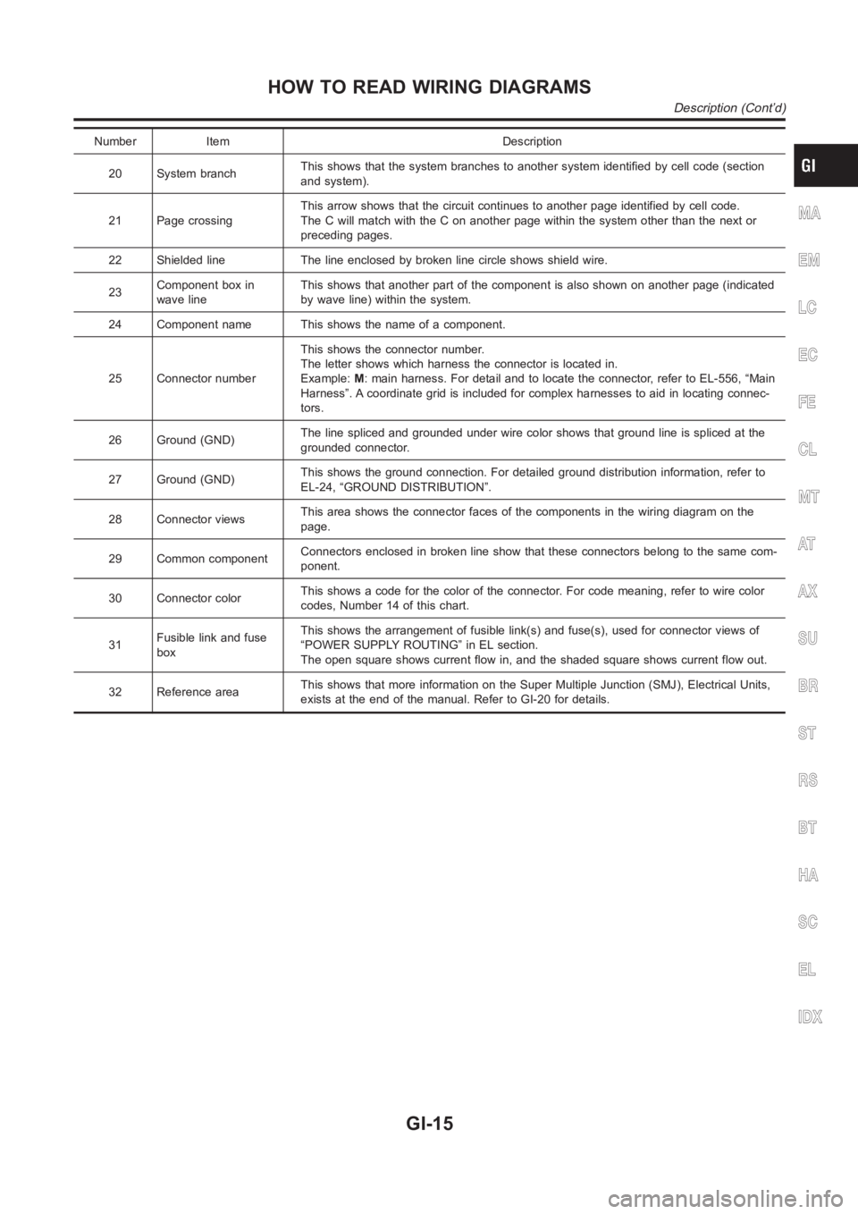
Number Item Description
20 System branchThis shows that the system branches to another system identified by cell code (section
and system).
21 Page crossingThis arrow shows that the circuit continues to another page identified by cell code.
The C will match with the C on another page within the system other than the next or
preceding pages.
22 Shielded line The line enclosed by broken line circle shows shield wire.
23Component box in
wave lineThis shows that another part of the component is also shown on another page (indicated
by wave line) within the system.
24 Component name This shows the name of a component.
25 Connector numberThis shows the connector number.
The letter shows which harness the connector is located in.
Example:M: main harness. For detail and to locate the connector, refer to EL-556, “Main
Harness”. A coordinate grid is included for complex harnesses to aid in locating connec-
tors.
26 Ground (GND)The line spliced and grounded under wire color shows that ground line is spliced at the
grounded connector.
27 Ground (GND)This shows the ground connection. For detailed ground distribution information, refer to
EL-24, “GROUND DISTRIBUTION”.
28 Connector viewsThis area shows the connector faces of the components in the wiring diagramon the
page.
29 Common componentConnectors enclosed in broken line show that these connectors belong to thesamecom-
ponent.
30 Connector colorThis shows a code for the color of the connector. For code meaning, refer to wire color
codes, Number 14 of this chart.
31Fusible link and fuse
boxThis shows the arrangement of fusible link(s) and fuse(s), used for connector views of
“POWER SUPPLY ROUTING” in EL section.
The open square shows current flow in, and the shaded square shows current flow out.
32 Reference areaThis shows that more information on the Super Multiple Junction (SMJ), Electrical Units,
exists at the end of the manual. Refer to GI-20 for details.
MA
EM
LC
EC
FE
CL
MT
AT
AX
SU
BR
ST
RS
BT
HA
SC
EL
IDX
HOW TO READ WIRING DIAGRAMS
Description (Cont’d)
GI-15
Page 23 of 3189
manual.
Fuse block — Junction box (J/B)
Fuse block — Junction box (J/B) connector number is shown in the
Reference Area of the wiring diagram. For connector terminal and
fuse arrangement, refer to the “FUSE BLOCK — Junction Box
(J/B)” electrical reference page at the end of the manual.
Fuse and fusible link box
For fuse arrangement in the fuse and fusible link box, refer to the
“FUSE AND FUSIBLE LINK BOX” electrical reference page at the
end of the manual.
Electrical units
Electrical unit connector symbols are shown in the Connector Area
of the wiring diagram.
However, when there is not enough space to show the connector
terminal arrangement in the Connector Area of the wiring diagram,
the electrical unit connector number is shown in the Reference
Area of the wiring diagram. For electrical unit connector terminal
arrangement, refer to the “ELECTRICAL UNITS” electrical refer-
ence page at the end of the manual. Most of the electrical unit
connectors on this page are shown from the harness side of the
connector.
Joint connector
Joint connector symbols are shown in the connector area of the
wiring diagram. For connector internal wiring layout and joint con-
nector terminal arrangement, refer to the “JOINT CONNECTOR
(J/C)” electrical reference page at the end of the manual.
MA
EM
LC
EC
FE
CL
MT
AT
AX
SU
BR
ST
RS
BT
HA
SC
EL
IDX
HOW TO READ WIRING DIAGRAMS
Description (Cont’d)
GI-21
Page 3180 of 3189

Heated oxygen sensor 2 heater
(QG engine)................................EC-129, EC-640
Heated seat<0011001100110011001100110011001100110011001100110011001100110011001100110011001100110011001100110011001100110011001100110011001100110011001100110011001100110011001100110011001100110011001100110011001100
110028002f[-247
HEATER - Wiring diagram (manual
A/C) <0011001100110011001100110011001100110011001100110011001100110011001100110011001100110011001100110011001100110011001100110011001100110011001100110011001100110011001100110011001100110011001100110011001100
1100110011001100110011001100110011[..HA-23
Heater and cooling unit (Heater core)
(manual A/C) ...............................................HA-87
Heater and cooling unit (Heater core)........ATC-123
Heater unit (heater core) ............................ATC-130
Height (Dimensions) ........................................GI-44
HFC134a (R134a) system precaution
(manual A/C) .................................................HA-2
HFC134a (R134a) system precaution............ATC-4
HFC134a (R134a) system service pro-
cedure (manual A/C)...................................HA-77
HFC134a (R134a) system service
procedure ................................................ATC-133
HFC134a (R134a) system service tools
(manual A/C) ...............................................HA-10
HFC134a (R134a) system service tools ......ATC-11
HFC134a system service equipment
precaution (manual A/C) ...............................HA-6
HFC134a system service equipment
precaution <0011001100110011001100110011001100110011001100110011001100110011001100110011001100110011001100110011001100110011001100110011001100110011001100110011001100110011001100110011001100110011001100110011001100
110024>TC-7
HO2S1 - Wiring diaram
(QG engine) ................EC-152, EC-159, EC-169,
EC-510, EC-516
HO2S1H - Wiring diagram (QG engine) ......EC-125
HO2S2 - Wiring diagram
(QG engine) ................EC-175, EC-182, EC-312,
EC-320, EC-522
HO2S2H - Wiring diagram (QG engine) ......EC-131
Hood<0011001100110011001100110011001100110011001100110011001100110011001100110011001100110011001100110011001100110011001100110011001100110011001100110011001100110011001100110011001100110011001100110011001100
1100110011001100110011001100110011[.......BT-7
HORN - Wiring diagram................................EL-170
Horn <0011001100110011001100110011001100110011001100110011001100110011001100110011001100110011001100110011001100110011001100110011001100110011001100110011001100110011001100110011001100110011001100110011001100
1100110011001100110011001100110011[...EL-170
How to erase DTC for OBD system
(QG engine)..................................EC-48, EC-431
How to erase DTC for OBD system
(YD engine).................................................EC-34
HSEAT - Wiring diagram ......................EL-246, 247
I
IATS - Wiring diagram (QG engine) .............EC-142
IATSEN - Wiring diagram (QG engine) ........EC-646
Identification plate............................................GI-41
Identification .....................................ATC-9, ATC-10
Idle air volume learning
(QG engine)..................................EC-31, EC-426
Idle speed (QG engine) ...................EC-65, EC-444
Idle speed (YD engine) ..................................EC-48
Ignition coil (QG engine) ................EC-366, EC-662
Ignition coil (QG engine) ................................EM-24
Ignition control system
(QG engine)................................EC-366, EC-662
Ignition timing (QG engine)..............EC-65, EC-444
IGNSYS - Wiring diagram
(QG engine)................................EC-367, EC-663
ILL - Wiring diagram .......................................EL-76
Illumination <0011001100110011001100110011001100110011001100110011001100110011001100110011001100110011001100110011001100110011001100110011001100110011001100110011001100110011001100110011001100110011001100110011001100
11[...EL-75In vehicle sensor ........ATC-103, ATC-105, ATC-117
INJECT - Wiring diagram
(QG engine)................................EC-377, EC-696
Injection nozzle (YD engine) ..........................EC-21
Injector (QG engine) ......................EC-376, EC-695
Input shaft (FF M/T).....................MT-36, 64, 93, 98
Instrument panel .............................................BT-25
INT/L - Wiring diagram..................................EL-108
Intake air temperature sensor
(QG engine)................................EC-141, EC-645
Intake door control linkage adjustment ........ATC-67
Intake door motor .........................ATC-66, ATC-122
Intake manifold (QG engine) .........................EM-16
Intake sensor ..............................ATC-109, ATC-119
Intake valve timing control
(QG engine) .................EC-120, EC-273, EC-685
Intake valve timing control solenoid
valve (QG engine) ......................EC-273, EC-685
Interior lamp on-off control........................EL-81, 83
Interior lamp <0011001100110011001100110011001100110011001100110011001100110011001100110011001100110011001100110011001100110011001100110011001100110011001100110011001100110011001100110011001100110011001100110011001100
11[.EL-80
Interior <0011001100110011001100110011001100110011001100110011001100110011001100110011001100110011001100110011001100110011001100110011001100110011001100110011001100110011001100110011001100110011001100110011001100
110011001100110011[......BT-31
ISO 15031-2 Terminology ................................GI-51
ISO 15031-5 Mode 1 - 9 (QG engine) ...........EC-36
IVC - Wiring diagram (QG engine)...............EC-274
IVC/V - Wiring diagram (QG engine) ...........EC-687
J
Jacking points ..................................................GI-46
Joint connector (J/C) ....................................Foldout
Junction box (J/B).........................................Foldout
K
Keyless entry system - See Multi-re-
mote control system ..................................EL-352
Knock sensor (KS) (QG engine) ....EC-231, EC-552
Knuckle spindle ................................................AX-5
KS - Wiring diagram
(QG engine)................................EC-232, EC-553
L
LAN system circuit........................................ATC-57
Length (Dimensions) .......................................GI-44
License lamp <0011001100110011001100110011001100110011001100110011001100110011001100110011001100110011001100110011001100110011001100110011001100110011001100110011001100110011001100110011001100110011001100110011001100
110028[L-55
Lifting points ....................................................GI-47
Line pressure solenoid valve ........................AT-159
Line pressure test (A/T) .....................AT-67, AT-266
Liquid gasket application (QG engine) ............EM-4
Liquid gasket application (YD engine) .............EM-3
LOAD - Wiring diagram
(QG engine)................................EC-394, EC-713
Location of electrical units ............................EL-543
Lock, door <0011001100110011001100110011001100110011001100110011001100110011001100110011001100110011001100110011001100110011001100110011001100110011001100110011001100110011001100110011001100110011001100110011001100
11001100110011[.BT-21
Lubricant (R134a) A/C (manual A/C) .............HA-79
Lubricant (R134a) A/C......................ATC-5, ATC-20
ALPHABETICAL INDEX
IDX-6
Page 3186 of 3189
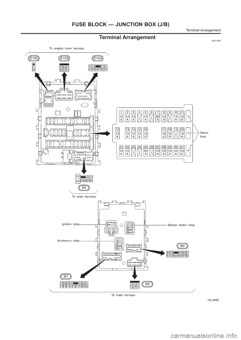
Terminal ArrangementNJEL0493
YEL466D
FUSE BLOCK — JUNCTION BOX (J/B)
Terminal Arrangement