2003 NISSAN ALMERA N16 fuse chart
[x] Cancel search: fuse chartPage 17 of 3189
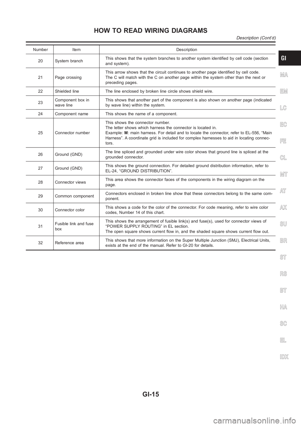
Number Item Description
20 System branchThis shows that the system branches to another system identified by cell code (section
and system).
21 Page crossingThis arrow shows that the circuit continues to another page identified by cell code.
The C will match with the C on another page within the system other than the next or
preceding pages.
22 Shielded line The line enclosed by broken line circle shows shield wire.
23Component box in
wave lineThis shows that another part of the component is also shown on another page (indicated
by wave line) within the system.
24 Component name This shows the name of a component.
25 Connector numberThis shows the connector number.
The letter shows which harness the connector is located in.
Example:M: main harness. For detail and to locate the connector, refer to EL-556, “Main
Harness”. A coordinate grid is included for complex harnesses to aid in locating connec-
tors.
26 Ground (GND)The line spliced and grounded under wire color shows that ground line is spliced at the
grounded connector.
27 Ground (GND)This shows the ground connection. For detailed ground distribution information, refer to
EL-24, “GROUND DISTRIBUTION”.
28 Connector viewsThis area shows the connector faces of the components in the wiring diagramon the
page.
29 Common componentConnectors enclosed in broken line show that these connectors belong to thesamecom-
ponent.
30 Connector colorThis shows a code for the color of the connector. For code meaning, refer to wire color
codes, Number 14 of this chart.
31Fusible link and fuse
boxThis shows the arrangement of fusible link(s) and fuse(s), used for connector views of
“POWER SUPPLY ROUTING” in EL section.
The open square shows current flow in, and the shaded square shows current flow out.
32 Reference areaThis shows that more information on the Super Multiple Junction (SMJ), Electrical Units,
exists at the end of the manual. Refer to GI-20 for details.
MA
EM
LC
EC
FE
CL
MT
AT
AX
SU
BR
ST
RS
BT
HA
SC
EL
IDX
HOW TO READ WIRING DIAGRAMS
Description (Cont’d)
GI-15
Page 2238 of 3189
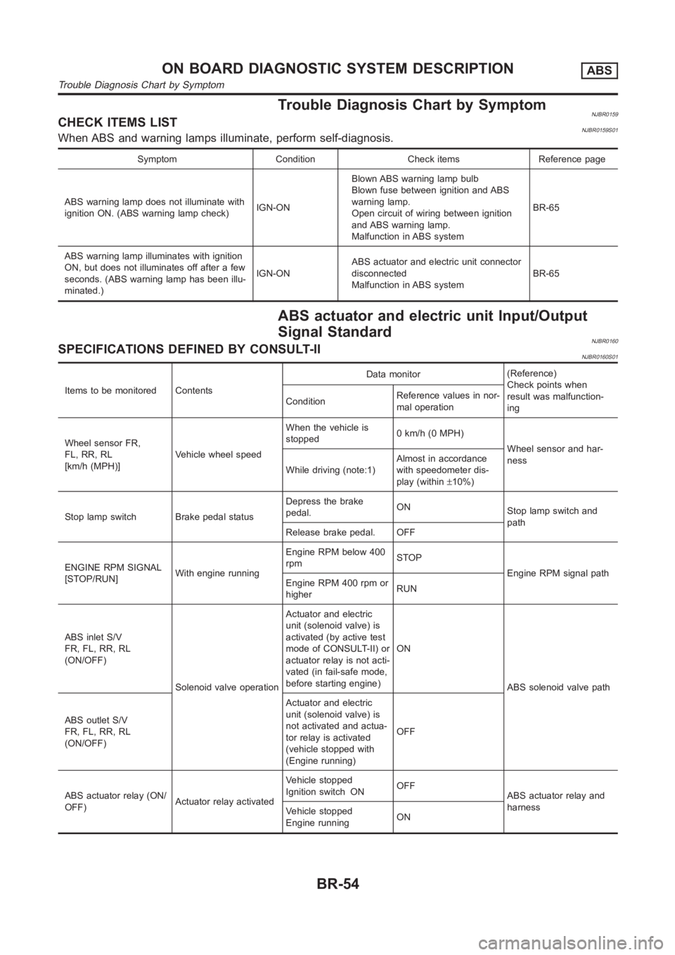
Trouble Diagnosis Chart by SymptomNJBR0159CHECK ITEMS LISTNJBR0159S01When ABS and warning lamps illuminate, perform self-diagnosis.
Symptom Condition Check items Reference page
ABS warning lamp does not illuminate with
ignition ON. (ABS warning lamp check)IGN-ONBlown ABS warning lamp bulb
Blown fuse between ignition and ABS
warning lamp.
Open circuit of wiring between ignition
and ABS warning lamp.
Malfunction in ABS systemBR-65
ABS warning lamp illuminates with ignition
ON, but does not illuminates off after a few
seconds. (ABS warning lamp has been illu-
minated.)IGN-ONABS actuator and electric unit connector
disconnected
Malfunction in ABS systemBR-65
ABS actuator and electric unit Input/Output
Signal Standard
NJBR0160SPECIFICATIONS DEFINED BY CONSULT-IINJBR0160S01
Items to be monitored ContentsData monitor(Reference)
Check points when
result was malfunction-
ing ConditionReference values in nor-
mal operation
Wheel sensor FR,
FL, RR, RL
[km/h (MPH)]Vehicle wheel speedWhen the vehicle is
stopped0 km/h (0 MPH)
Wheel sensor and har-
ness
While driving (note:1)Almost in accordance
with speedometer dis-
play (within±10%)
Stop lamp switch Brake pedal statusDepress the brake
pedal.ON
Stop lamp switch and
path
Release brake pedal. OFF
ENGINE RPM SIGNAL
[STOP/RUN]With engine runningEngine RPM below 400
rpmSTOP
Engine RPM signal path
Engine RPM 400 rpm or
higherRUN
ABS inlet S/V
FR, FL, RR, RL
(ON/OFF)
Solenoid valve operationActuator and electric
unit (solenoid valve) is
activated (by active test
mode of CONSULT-II) or
actuator relay is not acti-
vated (in fail-safe mode,
before starting engine)ON
ABS solenoid valve path
ABS outlet S/V
FR, FL, RR, RL
(ON/OFF)Actuator and electric
unit (solenoid valve) is
not activated and actua-
tor relay is activated
(vehicle stopped with
(Engine running)OFF
ABS actuator relay (ON/
OFF)Actuator relay activatedVehicle stopped
Ignition switch ONOFF
ABS actuator relay and
harness
Vehicle stopped
Engine runningON
ON BOARD DIAGNOSTIC SYSTEM DESCRIPTIONABS
Trouble Diagnosis Chart by Symptom
BR-54
Page 2628 of 3189
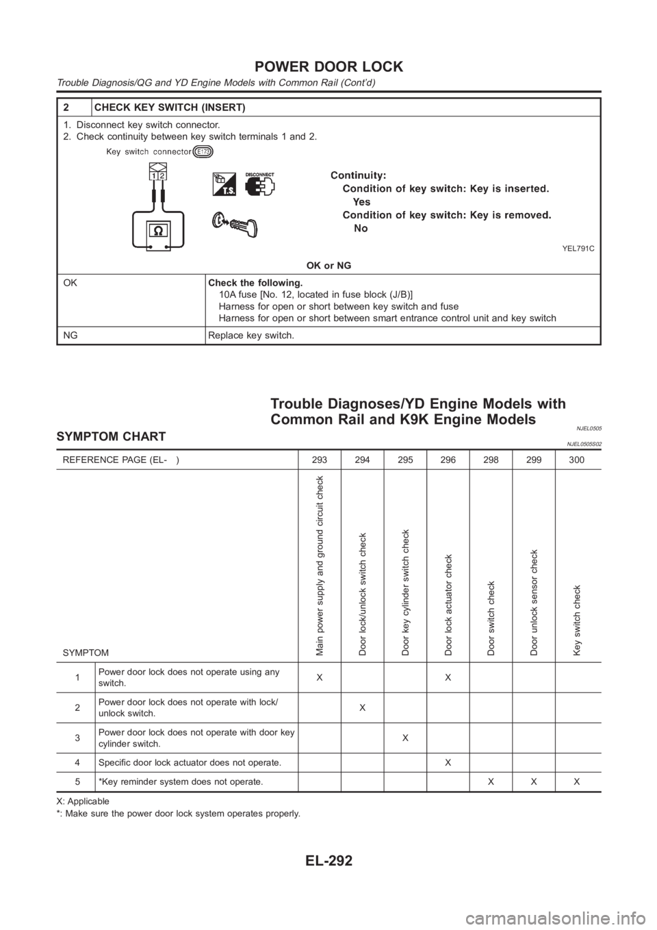
2 CHECK KEY SWITCH (INSERT)
1. Disconnect key switch connector.
2. Check continuity between key switch terminals 1 and 2.
YEL791C
OK or NG
OKCheck the following.
10A fuse [No. 12, located in fuse block (J/B)]
Harness for open or short between key switch and fuse
Harness for open or short between smart entrance control unit and key switch
NG Replace key switch.
Trouble Diagnoses/YD Engine Models with
Common Rail and K9K Engine Models
NJEL0505SYMPTOM CHARTNJEL0505S02
REFERENCE PAGE (EL- ) 293 294 295 296 298 299 300
SYMPTOM
Main power supply and ground circuit check
Door lock/unlock switch check
Door key cylinder switch check
Door lock actuator check
Door switch check
Door unlock sensor check
Key switch check
1Power door lock does not operate using any
switch.XX
2Power door lock does not operate with lock/
unlock switch.X
3Power door lock does not operate with door key
cylinder switch.X
4 Specific door lock actuator does not operate. X
5 *Key reminder system does not operate. X X X
X: Applicable
*: Make sure the power door lock system operates properly.
POWER DOOR LOCK
Trouble Diagnosis/QG and YD Engine Models with Common Rail (Cont’d)
EL-292
Page 2731 of 3189
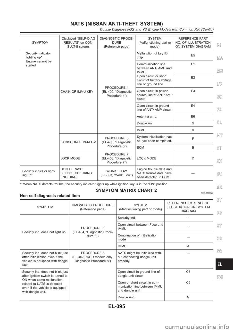
SYMPTOMDisplayed “SELF-DIAG
RESULTS” on CON-
SULT-II screen.DIAGNOSTIC PROCE-
DURE
(Reference page)SYSTEM
(Malfunctioning part or
mode)REFERENCE PART
NO. OF ILLUSTRATION
ON SYSTEM DIAGRAM
Security indicator
lighting up*
Engine cannot be
started
CHAIN OF IMMU-KEYPROCEDURE 4
(EL-400, “Diagnostic
Procedure 4”)Malfunction of key ID
chipE5
Communication line
between ANT/ AMP and
IMMU:
Open circuit or short
circuit of battery voltage
line or ground lineE1
E2
Open circuit in power
source line of ANT/ AMP
circuitE3
Open circuit in ground
line of ANT/ AMP circuitE4
Antenna amp. E6
Dongle unit G
IMMU A
ID DISCORD, IMM-ECMPROCEDURE 5
(EL-403, “Diagnostic
Procedure 5”)System initialization has
not yet been completed.F
ECM B
LOCK MODEPROCEDURE 7
(EL-406, “Diagnostic
Procedure 7”)LOCK MODE D
Security indicator light-
ing up*DON’T ERASE
BEFORE CHECKING
ENG DIAGWORK FLOW
(EL-393, “Work Flow”)Engine trouble data and
NATS trouble data have
been detected in ECM—
*: When NATS detects trouble, the security indicator lights up while ignition key is in the “ON” position.
SYMPTOM MATRIX CHART 2NJEL0590S03Non self-diagnosis related item
SYMPTOMDIAGNOSTIC PROCEDURE
(Reference page)SYSTEM
(Malfunctioning part or mode)REFERENCE PART NO. OF
ILLUSTRATION ON SYSTEM
DIAGRAM
Security ind. does not light up.PROCEDURE 6
(EL-404, “Diagnostic Proce-
dure 6”)Security ind. —
Open circuit between Fuse and
IMMU—
Continuation of initialization
mode—
IMMU A
Security ind. does not blink just
after initialization even if the
vehicle is equipped with dongle
unit.PROCEDURE 8
(EL-407, “RHD models only:
Diagnostic Procedure 8”)NATS might be initialized with-
out connecting dongle unit
properly.—
Security ind. does not blink just
after ignition switch is turned to
ON when some malfunction
related to NATS is detected
even if the vehicle is equipped
with dongle unit.Open circuit in ground line of
dongle unit circuitC6
Open or short circuit in com-
munication line between IMMU
and dongle unitC5
Dongle unit G
GI
MA
EM
LC
EC
FE
CL
MT
AT
AX
SU
BR
ST
RS
BT
HA
SC
IDX
NATS (NISSAN ANTI-THEFT SYSTEM)
Trouble Diagnoses/QG and YD Engine Models with Common Rail (Cont’d)
EL-395
Page 2733 of 3189
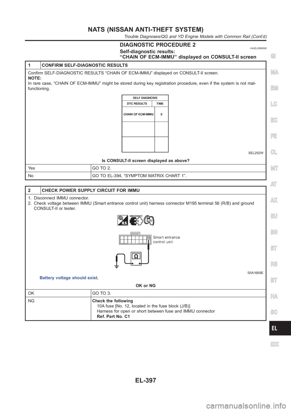
DIAGNOSTIC PROCEDURE 2=NJEL0590S06Self-diagnostic results:
“CHAIN OF ECM-IMMU” displayed on CONSULT-II screen
1 CONFIRM SELF-DIAGNOSTIC RESULTS
Confirm SELF-DIAGNOSTIC RESULTS “CHAIN OF ECM-IMMU” displayed on CONSULT-II screen.
NOTE:
In rare case, “CHAIN OF ECM-IMMU” might be stored during key registration procedure, even if the system is not mal-
functioning.
SEL292W
Is CONSULT-II screen displayed as above?
Ye s G O T O 2 .
No GO TO EL-394, “SYMPTOM MATRIX CHART 1”.
2 CHECK POWER SUPPLY CIRCUIT FOR IMMU
1. Disconnect IMMU connector.
2. Check voltage between IMMU (Smart entrance control unit) harness connector M195 terminal 56 (R/B) and ground
CONSULT-II or tester.
SIIA1669E
Battery voltage should exist.
OK or NG
OK GO TO 3.
NGCheck the following
10A fuse [No. 12, located in the fuse block (J/B)]
Harness for open or short between fuse and IMMU connector
Ref. Part No. C1
GI
MA
EM
LC
EC
FE
CL
MT
AT
AX
SU
BR
ST
RS
BT
HA
SC
IDX
NATS (NISSAN ANTI-THEFT SYSTEM)
Trouble Diagnoses/QG and YD Engine Models with Common Rail (Cont’d)
EL-397
Page 2750 of 3189
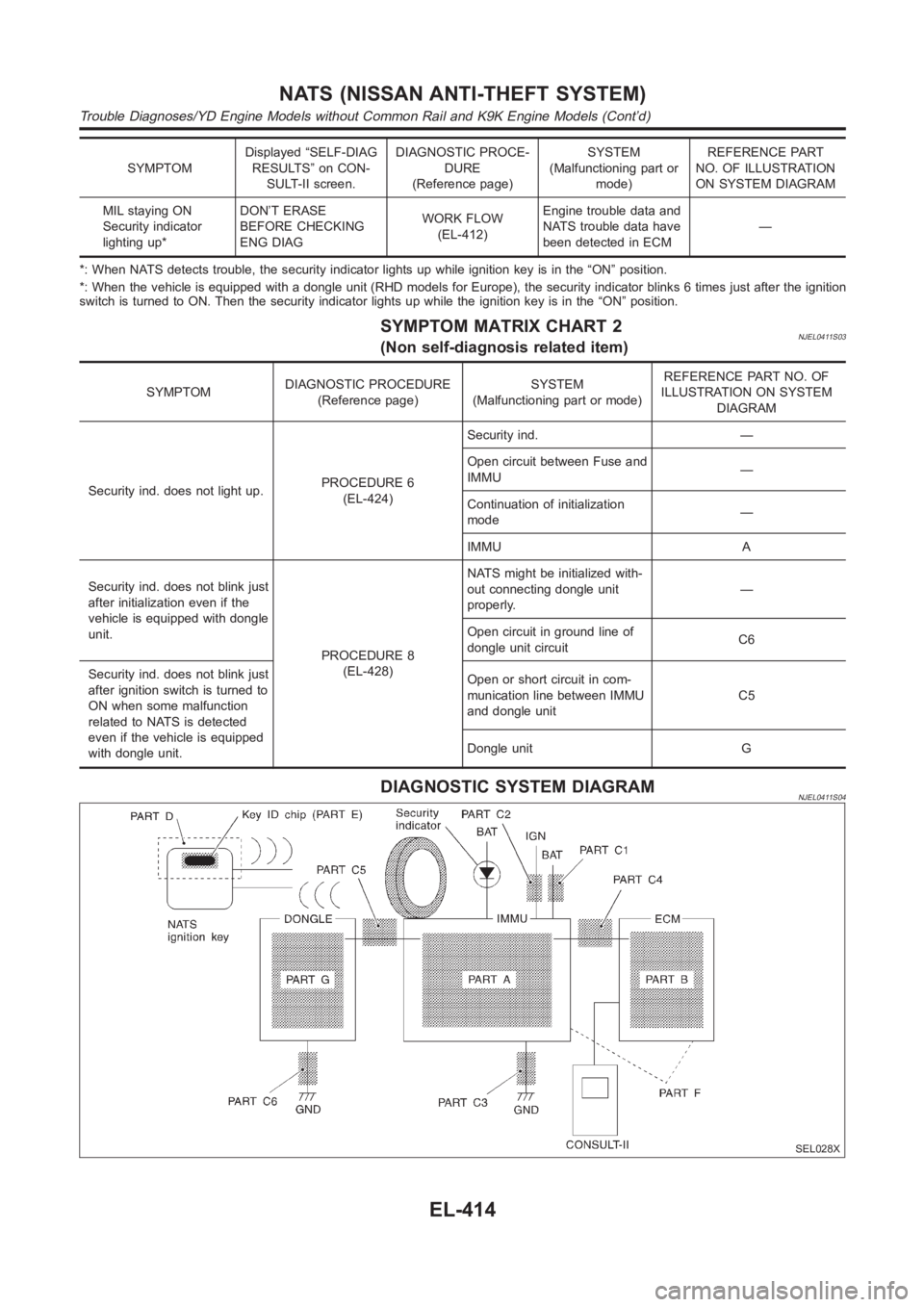
SYMPTOMDisplayed “SELF-DIAG
RESULTS” on CON-
SULT-II screen.DIAGNOSTIC PROCE-
DURE
(Reference page)SYSTEM
(Malfunctioning part or
mode)REFERENCE PART
NO. OF ILLUSTRATION
ON SYSTEM DIAGRAM
MIL staying ON
Security indicator
lighting up*DON’T ERASE
BEFORE CHECKING
ENG DIAGWORK FLOW
(EL-412)Engine trouble data and
NATS trouble data have
been detected in ECM—
*: When NATS detects trouble, the security indicator lights up while ignition key is in the “ON” position.
*: When the vehicle is equipped with a dongle unit (RHD models for Europe), the security indicator blinks 6 times just after the ignition
switch is turned to ON. Then the security indicator lights up while the ignition key is in the “ON” position.
SYMPTOM MATRIX CHART 2NJEL0411S03(Non self-diagnosis related item)
SYMPTOMDIAGNOSTIC PROCEDURE
(Reference page)SYSTEM
(Malfunctioning part or mode)REFERENCE PART NO. OF
ILLUSTRATION ON SYSTEM
DIAGRAM
Security ind. does not light up.PROCEDURE 6
(EL-424)Security ind. —
Open circuit between Fuse and
IMMU—
Continuation of initialization
mode—
IMMU A
Security ind. does not blink just
after initialization even if the
vehicle is equipped with dongle
unit.
PROCEDURE 8
(EL-428)NATS might be initialized with-
out connecting dongle unit
properly.—
Open circuit in ground line of
dongle unit circuitC6
Security ind. does not blink just
after ignition switch is turned to
ON when some malfunction
related to NATS is detected
even if the vehicle is equipped
with dongle unit.Open or short circuit in com-
munication line between IMMU
and dongle unitC5
Dongle unit G
DIAGNOSTIC SYSTEM DIAGRAMNJEL0411S04
SEL028X
NATS (NISSAN ANTI-THEFT SYSTEM)
Trouble Diagnoses/YD Engine Models without Common Rail and K9K Engine Models (Cont’d)
EL-414
Page 2752 of 3189

DIAGNOSTIC PROCEDURE 2=NJEL0411S06Self-diagnostic results:
“CHAIN OF ECM-IMMU” displayed on CONSULT-II screen
1 CONFIRM SELF-DIAGNOSTIC RESULTS
Confirm SELF-DIAGNOSTIC RESULTS “CHAIN OF ECM-IMMU” displayed on CONSULT-II screen.
NOTE:
In rare case, “CHAIN OF ECM-IMMU” might be stored during key registration procedure, even if the system is not mal-
functioning.
SEL366X
Is CONSULT-II screen displayed as above?
Ye s G O T O 2 .
No GO TO SYMPTOM MATRIX CHART 1.
2 CHECK POWER SUPPLY CIRCUIT FOR IMMU
1. Disconnect IMMU connector.
2. Check voltage between terminal 8 of IMMU and ground with CONSULT-II or tester.
SEL302WB
OK or NG
OK GO TO 3.
NGCheck the following
10A fuse (No. 36, located in the fusible link and fuse box) — (Gasoline engine)
20A fuse (No. 34, located in the fusible link and fuse box) — (Diesel engine)
Harness for open or short between fuse and IMMU connector
Ref. Part No. C1
NATS (NISSAN ANTI-THEFT SYSTEM)
Trouble Diagnoses/YD Engine Models without Common Rail and K9K Engine Models (Cont’d)
EL-416
Page 3081 of 3189
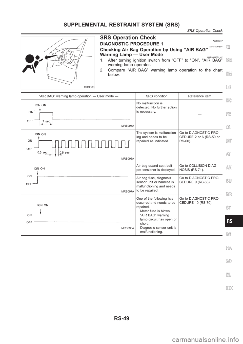
SRS800
SRS Operation CheckNJRS0047DIAGNOSTIC PROCEDURE 1NJRS0047S01Checking Air Bag Operation by Using “AIR BAG”
Warning Lamp — User Mode
NJRS0047S01011. After turning ignition switch from “OFF” to “ON”, “AIR BAG”
warning lamp operates.
2. Compare “AIR BAG” warning lamp operation to the chart
below.
“AIR BAG” warning lamp operation — User mode — SRS condition Reference item
MRS095A
No malfunction is
detected. No further action
is necessary.
—
MRS096A
The system is malfunction-
ing and needs to be
repaired as indicated.Go to DIAGNOSTIC PRO-
CEDURE 2 or 6 (RS-50 or
RS-60).
MRS097A
Air bag or/and seat belt
pre-tensioner is deployed.Go to COLLISION DIAG-
NOSIS (RS-71).
Air bag fuse, diagnosis
sensor unit or harness is
malfunctioning and needs
to be repaired.Go to DIAGNOSTIC PRO-
CEDURE 9 (RS-68).
MRS098A
One of the following has
occurred and needs to be
repaired.
Meter fuse is blown.
“AIR BAG” warning
lamp circuit has open or
short.
Diagnosis sensor unit is
malfunctioning.Go to DIAGNOSTIC PRO-
CEDURE 10 (RS-70).
GI
MA
EM
LC
EC
FE
CL
MT
AT
AX
SU
BR
ST
BT
HA
SC
EL
IDX
SUPPLEMENTAL RESTRAINT SYSTEM (SRS)
SRS Operation Check
RS-49