2003 NISSAN ALMERA N16 Can communicat
[x] Cancel search: Can communicatPage 38 of 3189

NJGI0007
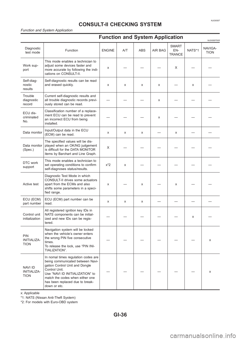
Function and System ApplicationNJGI0007S05
Diagnostic
test modeFunction ENGINE A/T ABS AIR BAGSMART
EN-
TRANCENATS*1NAVIGA-
TION
Work sup-
portThis mode enables a technician to
adjust some devices faster and
more accurate by following the indi-
cations on CONSULT-II.x ———X——
Self-diag-
nostic
resultsSelf-diagnostic results can be read
anderasedquickly. x x x x—x—
Trouble
diagnostic
recordCurrent self-diagnostic results and
all trouble diagnostic records previ-
ously stored can be read.——— x ———
ECU dis-
criminated
No.Classification number of a replace-
ment ECU can be read to prevent
an incorrect ECU from being
installed.——— x ———
Data monitorInput/Output data in the ECU
(ECM) can be read.x x x—x——
Data monitor
(Spec.)The specified values will be dis-
played when an OK/NG judgement
is difficult for the DATA MONITOR
items by Barchart and Line Graph.X ——————
DTC work
supportThis mode enables a technician to
set operating conditions to confirm
self-diagnoses status/results.x*2x —————
Active testDiagnostic Test Mode in which
CONSULT-II drives some actuators
apart from the ECMs and also
shifts some parameters in a speci-
fied range.x—x—x——
ECU (ECM)
part numberECU (ECM) part number can be
read.x x x ————
Control unit
initializationAll registered ignition key IDs in
NATS components can be initial-
ized and new IDs can be regis-
tered.————— x —
PIN
INITIALIZA-
TIONNavigation system will be locked
when the vehicle’s owner enters
the wrong PIN five consecutive
times.
To release the lock, use “PIN INI-
TIALIZATION”.—————— x
NAVI ID
INITIALIZA-
TIONIn nomal times regulation codes are
being communicated between Navi-
gation Control Unit and Dongle
Control Unit.
Use “NAVI ID INITIALIZATION” to
match the codes when either one
has been replaced due to break-
down or etc.—————— x
x: Applicable
*1: NATS (Nissan Anti-Theft System)
*2: For models with Euro-OBD system
CONSULT-II CHECKING SYSTEM
Function and System Application
GI-36
Page 331 of 3189

EC-1
ENGINE CONTROL SYSTEM
B ENGINE
CONTENTS
C
D
E
F
G
H
I
J
K
L
M
SECTION
A
EC
ENGINE CONTROL SYSTEM
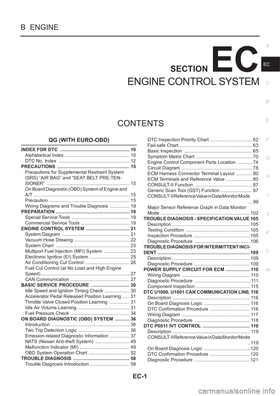
QG (WITH EURO-OBD)
INDEX FOR DTC ...................................................... 10
Alphabetical Index .................................................. 10
DTC No. Index ....................................................... 12
PRECAUTIONS ........................................................ 15
Precautions for Supplemental Restraint System
(SRS) “AIR BAG” and “SEAT BELT PRE-TEN-
SIONER” ................................................................ 15
On Board Diagnostic (OBD) System of Engine and
A/T .......................................................................... 15
Precaution .............................................................. 15
Wiring Diagrams and Trouble Diagnosis ................ 18
PREPARATION ......................................................... 19
Special Service Tools ............................................. 19
Commercial Service Tools ...................................... 19
ENGINE CONTROL SYSTEM .................................. 21
System Diagram ..................................................... 21
Vacuum Hose Drawing ........................................... 22
System Chart ......................................................... 23
Multiport Fuel Injection (MFI) System .................... 23
Electronic Ignition (EI) System ............................... 25
Air Conditioning Cut Control ................................... 26
Fuel Cut Control (at No Load and High Engine
Speed) .................................................................... 27
CAN Communication .............................................. 27
BASIC SERVICE PROCEDURE .............................. 30
Idle Speed and Ignition Timing Check .................... 30
Accelerator Pedal Released Position Learning ...... 31
Throttle Valve Closed Position Learning ................ 31
Idle Air Volume Learning ........................................ 31
Fuel Pressure Check .............................................. 34
ON BOARD DIAGNOSTIC (OBD) SYSTEM ............ 36
Introduction ............................................................ 36
Two Trip Detection Logic ........................................ 36
Emission-related Diagnostic Information ................ 37
NATS (Nissan Anti-theft System) ........................... 49
Malfunction Indicator (MI) ....................................... 49
OBD System Operation Chart ................................ 52
TROUBLE DIAGNOSIS ............................................ 58
Trouble Diagnosis Introduction ............................... 58DTC Inspection Priority Chart ................................. 62
Fail-safe Chart ........................................................ 63
Basic Inspection ..................................................... 65
Symptom Matrix Chart ............................................ 70
Engine Control Component Parts Location ............ 74
Circuit Diagram ....................................................... 78
ECM Harness Connector Terminal Layout ............. 80
ECM Terminals and Reference Value ..................
... 80
CONSULT-II Function ............................................. 87
Generic Scan Tool (GST) Function ......................... 97
CONSULT-II Reference Value in Data Monitor Mode
... 99
Major Sensor Reference Graph in Data Monitor
Mode .....................................................................102
TROUBLE DIAGNOSIS - SPECIFICATION VALUE .105
Description ............................................................105
Testing Condition ..................................................105
Inspection Procedure ............................................105
Diagnostic Procedure ...........................................106
TROUBLE DIAGNOSIS FOR INTERMITTENT INCI-
DENT .......................................................................109
Description ............................................................109
Diagnostic Procedure ...........................................109
POWER SUPPLY CIRCUIT FOR ECM ...................110
Wiring Diagram .....................................................110
Diagnostic Procedure ............................................111
Component Inspection ..........................................115
DTC U1000, U1001 CAN COMMUNICATION LINE .116
Description ............................................................116
On Board Diagnosis Logic ....................................116
DTC Confirmation Procedure ...............................116
Wiring Diagram .....................................................117
Diagnostic Procedure ...........................................118
DTC P0011 IVT CONTROL .....................................119
Description ............................................................119
CONSULT-II Reference Value in Data Monitor Mode
.119
On Board Diagnosis Logic ....................................120
DTC Confirmation Procedure ...............................120
Diagnostic Procedure ...........................................121
Page 335 of 3189

EC-5
C
D
E
F
G
H
I
J
K
L
M
ECA Wiring Diagram .................................................... 353
Diagnostic Procedure ........................................... 354
DTC P1706 PNP SWITCH ...................................... 356
Component Description ........................................ 356
CONSULT-II Reference Value in Data Monitor Mode
. 356
On Board Diagnosis Logic ................................... 356
DTC Confirmation Procedure ............................... 356
Overall Function Check ........................................ 357
Wiring Diagram .................................................... 358
Diagnostic Procedure ........................................... 359
DTC P1805 BRAKE SWITCH ................................ 360
Description ........................................................... 360
CONSULT-II Reference Value in Data Monitor Mode
. 360
On Board Diagnosis Logic ................................... 360
DTC Confirmation Procedure ............................... 360
Wiring Diagram .................................................... 361
Diagnostic Procedure ........................................... 362
Component Inspection ......................................... 364
IGNITION SIGNAL .................................................. 365
Component Description ........................................ 365
Wiring Diagram .................................................... 366
Diagnostic Procedure ........................................... 369
Component Inspection ......................................... 373
Removal and Installation ...................................... 374
INJECTOR CIRCUIT ............................................... 375
Component Description ........................................ 375
CONSULT-II Reference Value in Data Monitor Mode
. 375
Wiring Diagram .................................................... 376
Diagnostic Procedure ........................................... 377
Component Inspection ......................................... 380
Removal and Installation ...................................... 380
FUEL PUMP CIRCUIT ............................................ 381
Description ........................................................... 381
CONSULT-II Reference Value in Data Monitor Mode
. 381
Wiring Diagram .................................................... 382
Diagnostic Procedure ........................................... 383
Component Inspection ......................................... 385
Removal and Installation ...................................... 386
REFRIGERANT PRESSURE SENSOR ................. 387
Component Description ........................................ 387
Wiring Diagram .................................................... 388
Diagnostic Procedure ........................................... 389
Removal and Installation ...................................... 391
ELECTRICAL LOAD SIGNAL ................................ 392
Description ...................................................
........ 392
CONSULT-II Reference Value in Data Monitor Mode
. 392
Wiring Diagram .................................................... 393
Diagnostic Procedure ........................................... 394
MI & DATA LINK CONNECTORS .......................... 397
Wiring Diagram—LHD Models ............................. 397
Wiring Diagram—RHD Models ............................ 398
EVAPORATIVE EMISSION SYSTEM ..................... 399
Description ........................................................... 399
Component Inspection ......................................... 401POSITIVE CRANKCASE VENTILATION ...............402
Description ............................................................402
Component Inspection ..........................................402
SERVICE DATA AND SPECIFICATIONS (SDS) ....404
Fuel Pressure .......................................................404
Idle Speed and Ignition Timing .............................404
Calculated Load Value ..........................................404
Mass Air Flow Sensor ...........................................404
Intake Air Temperature Sensor .............................404
Engine Coolant Temperature Sensor ...................404
Heated Oxygen Sensor 1 Heater .........................404
Heated Oxygen sensor 2 Heater ..........................404
Crankshaft Position Sensor (POS) .......................404
Camshaft Position Sensor (PHASE) ....................404
Throttle Control Motor ...........................................405
Injector ..................................................................405
Fuel Pump ............................................................405
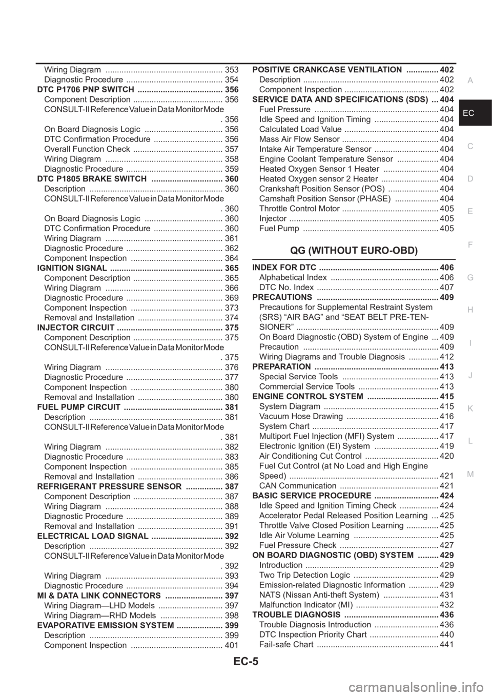
QG (WITHOUT EURO-OBD)
INDEX FOR DTC .....................................................406
Alphabetical Index ................................................406
DTC No. Index ......................................................407
PRECAUTIONS ......................................................409
Precautions for Supplemental Restraint System
(SRS) “AIR BAG” and “SEAT BELT PRE-TEN-
SIONER” ...............................................................409
On Board Diagnostic (OBD) System of Engine ....409
Precaution ............................................................409
Wiring Diagrams and Trouble Diagnosis ..............412
PREPARATION .......................................................413
Special Service Tools ...........................................413
Commercial Service Tools ....................................413
ENGINE CONTROL SYSTEM ................................415
System Diagram ...................................................415
Vacuum Hose Drawing .........................................416
System Chart ........................................................417
Multiport Fuel Injection (MFI) System ...................417
Electronic Ignition (EI) System .............................419
Air Conditioning Cut Control .................................420
Fuel Cut Control (at No Load and High Engine
Speed) ..................................................................421
CAN Communication ............................................421
BASIC SERVICE PROCEDURE .............................424
Idle Speed and Ignition Timing Check ..................424
Accelerator Pedal Released Position Learning ....425
Throttle Valve Closed Position Learning ...............425
Idle Air Volume Learning ......................................425
Fuel Pressure Check ............................................427
ON BOARD DIAGNOSTIC (OBD) SYSTEM ..........429
Introduction ...........................................................429
Two Trip Detection Logic ......................................429
Emission-related Diagnostic Information ..............429
NATS (Nissan Anti-theft System) .........................431
Malfunction Indicator (MI) .....................................432
TROUBLE DIAGNOSIS ..........................................436
Trouble Diagnosis Introduction .............................436
DTC Inspection Priority Chart ...............................440
Fail-safe Chart ......................................................441
Page 336 of 3189

EC-6
Basic Inspection ...................................................443
Symptom Matrix Chart ..........................................448
Engine Control Component Parts Location ..........452
Circuit Diagram .....................................................456
ECM Harness Connector Terminal Layout ...........458
ECM Terminals and Reference Value ...................458
CONSULT-II Function ...........................................465
CONSULT-II Reference Value in Data Monitor Mode
.475
Major Sensor Reference Graph in Data Monitor
Mode .....................................................................479
TROUBLE DIAGNOSIS - SPECIFICATION VALUE .481
Description ............................................................481
Testing Condition ..................................................481
Inspection Procedure ............................................481
Diagnostic Procedure ...........................................482
TROUBLE DIAGNOSIS FOR INTERMITTENT INCI-
DENT .......................................................................485
Description ............................................................485
Diagnostic Procedure ...........................................485
POWER SUPPLY CIRCUIT FOR ECM ...................486
Wiring Diagram .....................................................486
Diagnostic Procedure ...........................................487
Component Inspection ..........................................491
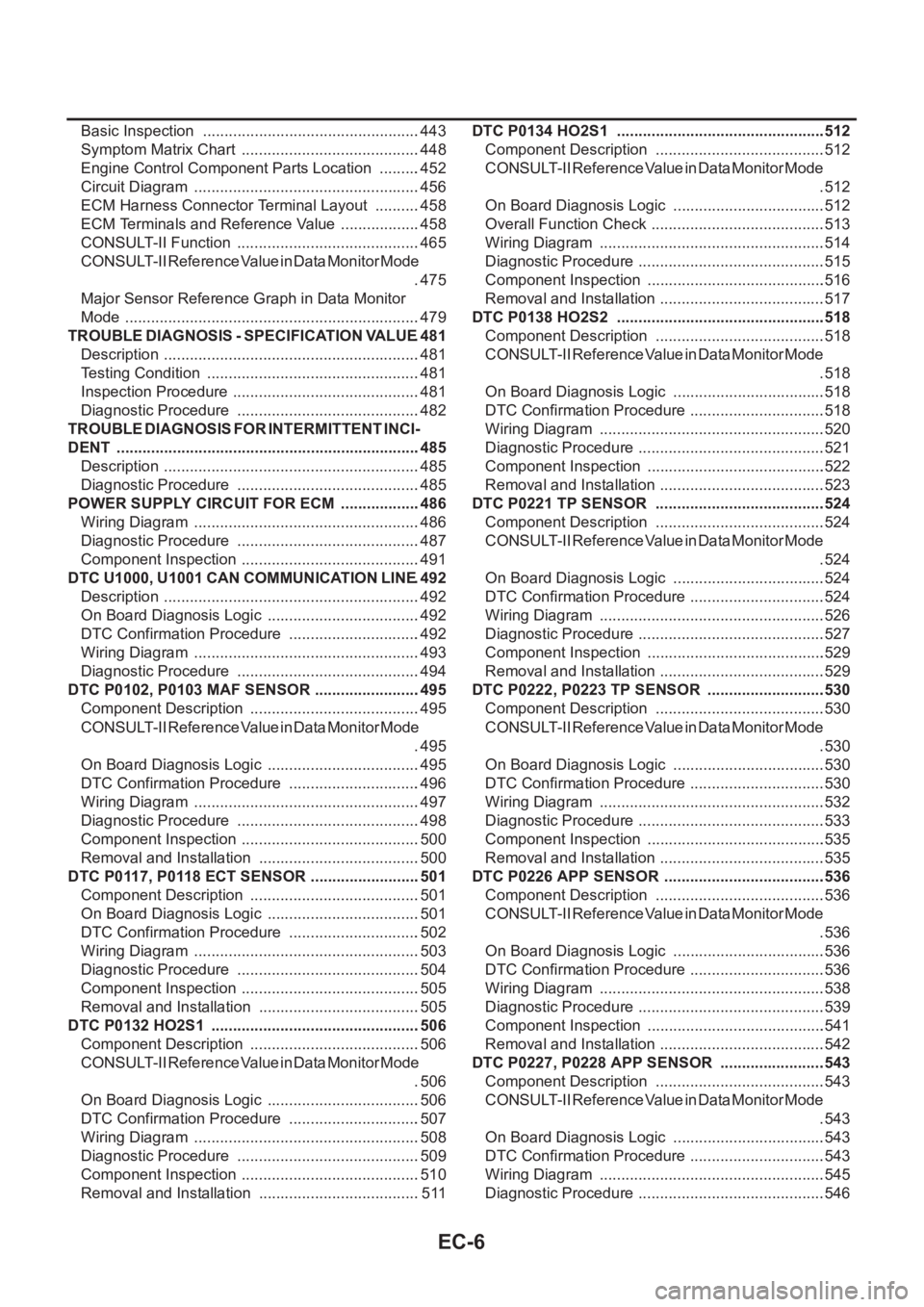
DTC U1000, U1001 CAN COMMUNICATION LINE .492
Description ............................................................492
On Board Diagnosis Logic ....................................492
DTC Confirmation Procedure ...............................492
Wiring Diagram .....................................................493
Diagnostic Procedure ...........................................494
DTC P0102, P0103 MAF SENSOR .........................495
Component Description ........................................495
CONSULT-II Reference Value in Data Monitor Mode
.495
On Board Diagnosis Logic ....................................495
DTC Confirmation Procedure ...............................496
Wiring Diagram .....................................................497
Diagnostic Procedure ...........................................498
Component Inspection ..........................................500
Removal and Installation ......................................500
DTC P0117, P0118 ECT SENSOR ..........................501
Component Description ........................................501
On Board Diagnosis Logic ....................................501
DTC Confirmation Procedure ...............................502
Wiring Diagram .....................................................503
Diagnostic Procedure ...........................................504
Component Inspection ..........................................505
Removal and Installation ......................................505
DTC P0132 HO2S1 .................................................506
Component Description ........................................506
CONSULT-II Reference Value in Data Monitor Mode
.506
On Board Diagnosis Logic ....................................506
DTC Confirmation Procedure ...............................507
Wiring Diagram .....................................................508
Diagnostic Procedure ...........................................509
Component Inspection ..........................................510
Removal and Installation ......................................511DTC P0134 HO2S1 ................................................ .512
Component Description ........................................512
CONSULT-II Reference Value in Data Monitor Mode
.512
On Board Diagnosis Logic ....................................512
Overall Function Check .........................................513
Wiring Diagram .....................................................514
Diagnostic Procedure ............................................515
Component Inspection ..........................................516
Removal and Installation .......................................517
DTC P0138 HO2S2 ................................................ .518
Component Description ........................................518
CONSULT-II Reference Value in Data Monitor Mode
.518
On Board Diagnosis Logic ....................................518
DTC Confirmation Procedure ................................518
Wiring Diagram .....................................................520
Diagnostic Procedure ............................................521
Component Inspection ..........................................522
Removal and Installation .......................................523
DTC P0221 TP SENSOR ........................................524
Component Description ........................................524
CONSULT-II Reference Value in Data Monitor Mode
.524
On Board Diagnosis Logic ....................................524
DTC Confirmation Procedure ................................524
Wiring Diagram .....................................................526
Diagnostic Procedure ............................................527
Component Inspection ..........................................529
Removal and Installation .......................................529
DTC P0222, P0223 TP SENSOR ............................530
Component Description ........................................530
CONSULT-II Reference Value in Data Monitor Mode
.530
On Board Diagnosis Logic ....................................530
DTC Confirmation Procedure ................................530
Wiring Diagram .....................................................532
Diagnostic Procedure ............................................533
Component Inspection ..........................................535
Removal and Installation ......................................
.535
DTC P0226 APP SENSOR ......................................536
Component Description ........................................536
CONSULT-II Reference Value in Data Monitor Mode
.536
On Board Diagnosis Logic ....................................536
DTC Confirmation Procedure ................................536
Wiring Diagram .....................................................538
Diagnostic Procedure ............................................539
Component Inspection ..........................................541
Removal and Installation .......................................542
DTC P0227, P0228 APP SENSOR .........................543
Component Description ........................................543
CONSULT-II Reference Value in Data Monitor Mode
.543
On Board Diagnosis Logic ....................................543
DTC Confirmation Procedure ................................543
Wiring Diagram .....................................................545
Diagnostic Procedure ............................................546
Page 340 of 3189
![NISSAN ALMERA N16 2003 Electronic Repair Manual EC-10
[QG (WITH EURO-OBD)]
INDEX FOR DTC
[QG (WITH EURO-OBD)]INDEX FOR DTCPFP:00024
Alphabetical IndexEBS00K2T
Check if the vehicle is a model with Euro-OBD (E-OBD) system or not by the “Type approv NISSAN ALMERA N16 2003 Electronic Repair Manual EC-10
[QG (WITH EURO-OBD)]
INDEX FOR DTC
[QG (WITH EURO-OBD)]INDEX FOR DTCPFP:00024
Alphabetical IndexEBS00K2T
Check if the vehicle is a model with Euro-OBD (E-OBD) system or not by the “Type approv](/manual-img/5/57350/w960_57350-339.png)
EC-10
[QG (WITH EURO-OBD)]
INDEX FOR DTC
[QG (WITH EURO-OBD)]INDEX FOR DTCPFP:00024
Alphabetical IndexEBS00K2T
Check if the vehicle is a model with Euro-OBD (E-OBD) system or not by the “Type approval number” on the
identification plate. Refer to GI-39.
NOTE:
If DTC U1000 or U1001 is displayed with other DTC, first perform the trouble diagnosis for DTC U1000,
U1001. Refer to EC-116, "
DTC U1000, U1001 CAN COMMUNICATION LINE" .
×: Applicable –: Not applicable
Items
(CONSULT-II screen terms)DTC*
1
TripMI lighting
upReference page
CONSULT-II
GST*
2ECM*3
A/T 1ST GR FNCTN P0731 0731 2×AT-133
A/T 2ND GR FNCTN P0732 0732 2×AT-139
A/T 3RD GR FNCTN P0733 0733 2×AT-145
A/T 4TH GR FNCTN P0734 0734 2×AT-151
APP SEN 1/CIRC P0227 0227 1×EC-218
APP SEN 1/CIRC P0228 0228 1×EC-218
APP SEN 2/CIRC P1227 1227 1×EC-345
APP SEN 2/CIRC P1228 1228 1×EC-345
APP SENSOR P0226 0226 1×EC-211
ATF TEMP SEN/CIRC P0710 0710 2×AT- 11 7
BRAKE SW/CIRCUIT P1805 1805 2 –EC-360
CAN COMM CIRCUIT U1000
1000*51×EC-116
CAN COMM CIRCUIT U1001
1001*52–EC-116
CKP SEN/CIRCUIT P0335 0335 2×EC-234
CMP SEN/CIRC-B1 P0340 0340 2×EC-240
CTP LEARNING P1225 1225 2 –EC-341
CTP LEARNING P1226 1226 2 –EC-343
CYL 1 MISFIRE P0301 0301 2×EC-225
CYL 2 MISFIRE P0302 0302 2×EC-225
CYL 3 MISFIRE P0303 0303 2×EC-225
CYL 4 MISFIRE P0304 0304 2×EC-225
ECM P0605 0605 1 or 2× or –EC-265
ECM BACK UP/CIRC P1065 1065 2×EC-268
ECT SEN/CIRCUIT P0117 0117 1×EC-144
ECT SEN/CIRCUIT P0118 0118 1×EC-144
ENG OVER TEMP P1217 1217 1×EC-324
ENGINE SPEED SIG P0725 0725 1×AT-129
ETC ACTR P1121 1121 1 or 2×EC-276
ETC FUNCTION/CIRC P1122 1122 1×EC-278
ETC MOT P1128 1128 1×EC-291
ETC MOT PWR P1124 1124 1×EC-285
ETC MOT PWR P1126 1126 1×EC-285
FUEL SYS-LEAN-B1 P0171 0171 2×EC-186
FUEL SYS-RICH-B1 P0172 0172 2×EC-193
HO2S1 (B1) P0132 0132 2×EC-149
Page 342 of 3189
![NISSAN ALMERA N16 2003 Electronic Repair Manual EC-12
[QG (WITH EURO-OBD)]
INDEX FOR DTC
*1: 1st trip DTC No. is the same as DTC No.
*2: These numbers are prescribed by ISO 15031-5.
*3: In Diagnostic Test Mode II (Self-diagnostic results), these nu NISSAN ALMERA N16 2003 Electronic Repair Manual EC-12
[QG (WITH EURO-OBD)]
INDEX FOR DTC
*1: 1st trip DTC No. is the same as DTC No.
*2: These numbers are prescribed by ISO 15031-5.
*3: In Diagnostic Test Mode II (Self-diagnostic results), these nu](/manual-img/5/57350/w960_57350-341.png)
EC-12
[QG (WITH EURO-OBD)]
INDEX FOR DTC
*1: 1st trip DTC No. is the same as DTC No.
*2: These numbers are prescribed by ISO 15031-5.
*3: In Diagnostic Test Mode II (Self-diagnostic results), these numbers are controlled by NISSAN.
*4: When engine is running.
*5: The troubleshooting for this DTC needs CONSULT-II.
*6: When the fail-safe operations for both self-diagnoses occur, the MI illuminates.
DTC No. IndexEBS00K2U
Check if the vehicle is a model with Euro-OBD (E-OBD) system or not by the “Type approval number” on the
identification plate. Refer to GI-39.
NOTE:
If DTC U1000 or U1001 is displayed with other DTC, first perform the trouble diagnosis for DTC U1000,
U1001. Refer to EC-116, "
DTC U1000, U1001 CAN COMMUNICATION LINE" .
×: Applicable –: Not applicable TW CATALYST SYS-B1 P0420 0420 2×EC-246
VEH SPD SEN/CIR AT*6P0720 0720 2×AT-123
VEH SPEED SEN/CIRC P0500 0500 2×EC-257
Items
(CONSULT-II screen terms)DTC*
1
TripMI lighting
upReference page
CONSULT-II
GST*
2ECM*3
DTC*1
Items
(CONSULT-II screen terms)TripMI lighting
upReference page
CONSULT-II
GST*
2ECM*3
No DTC
Flashing*4NO DTC IS DETECTED.
FURTHER TESTING
MAY BE REQUIRED.–
Flashing*4EC-50
U1000
1000*5CAN COMM CIRCUIT 1×EC-116
U1001
1001*5CAN COMM CIRCUIT 2 –EC-116
P0000 0000NO DTC IS DETECTED.
FURTHER TESTING
MAY BE REQUIRED.––—
P0011 0011 INT/V TIM CONT-B1 2 –EC-119
P0031 0031 HO2S1 HTR (B1) 2×EC-122
P0032 0032 HO2S1 HTR (B1) 2×EC-122
P0037 0037 HO2S2 HTR (B1) 2×EC-128
P0038 0038 HO2S2 HTR (B1) 2×EC-128
P0102 0102 MAF SEN/CIRCUIT 1×EC-134
P0103 0103 MAF SEN/CIRCUIT 1×EC-134
P0112 0112 IAT SEN/CIRCUIT 2×EC-140
P0113 0113 IAT SEN/CIRCUIT 2×EC-140
P0117 0117 ECT SEN/CIRCUIT 1×EC-144
P0118 0118 ECT SEN/CIRCUIT 1×EC-144
P0132 0132 HO2S1 (B1) 2×EC-149
P0133 0133 HO2S1 (B1) 2×EC-155
P0134 0134 HO2S1 (B1) 2×EC-165
P0138 0138 HO2S2 (B1) 2×EC-172
P0139 0139 HO2S2 (B1) 2×EC-178
P0171 0171 FUEL SYS-LEAN-B1 2×EC-186
P0172 0172 FUEL SYS-RICH-B1 2×EC-193
P0221 0221 TP SENSOR 1×EC-199
Page 353 of 3189
![NISSAN ALMERA N16 2003 Electronic Repair Manual ENGINE CONTROL SYSTEM
EC-23
[QG (WITH EURO-OBD)]
C
D
E
F
G
H
I
J
K
L
MA
EC
System ChartEBS00K34
*1: This sensor is not used to control the engine system under normal conditions.
*2: The signals are se NISSAN ALMERA N16 2003 Electronic Repair Manual ENGINE CONTROL SYSTEM
EC-23
[QG (WITH EURO-OBD)]
C
D
E
F
G
H
I
J
K
L
MA
EC
System ChartEBS00K34
*1: This sensor is not used to control the engine system under normal conditions.
*2: The signals are se](/manual-img/5/57350/w960_57350-352.png)
ENGINE CONTROL SYSTEM
EC-23
[QG (WITH EURO-OBD)]
C
D
E
F
G
H
I
J
K
L
MA
EC
System ChartEBS00K34
*1: This sensor is not used to control the engine system under normal conditions.
*2: The signals are sent to the ECM through CAN communication line.
*3: The output signals are sent from the ECM through CAN communication line.
Multiport Fuel Injection (MFI) SystemEBS00K35
INPUT/OUTPUT SIGNAL CHART
*1: Under normal conditions, this sensor is not for engine control operation.
*2: This signal is sent to the ECM through CAN communication line.
*3: ECM determines the start signal status by the signals of engine speed and battery voltage.
SYSTEM DESCRIPTION
The amount of fuel injected from the fuel injector is determined by the ECM. The ECM controls the length of
time the valve remains open (injection pulse duration). The amount of fuel injected is a program value in the
Input (Sensor) ECM Function Output (Actuator)
●Camshaft position sensor (PHASE)
●Crankshaft position sensor (POS)
●Mass air flow sensor
●Engine coolant temperature sensor
●Heated oxygen sensor 1
●Throttle position sensor
●Accelerator pedal position sensor
●Park/neutral position (PNP) switch
●Intake air temperature sensor
●Power steering pressure sensor
●Ignition switch
●Stop lamp switch
●Battery voltage
●Knock sensor
●Refrigerant pressure sensor
●Heated oxygen sensor 2*1
●TCM (Transmission control module)*2
●Air conditioner switch*2
●Vehicle speed signal*2
●Electrical load signal*2
Fuel injection & mixture ratio control Fuel injectors
Electronic ignition system Power transistor
Fuel pump control Fuel pump relay
On board diagnostic system
MI (On the instrument panel)
*3
Intake valve timing controlIntake valve timing control solenoid
valve
Heated oxygen sensor 1 heater control Heated oxygen sensor 1 heater
Heated oxygen sensor 2 heater control Heated oxygen sensor 2 heater
EVAP canister purge flow controlEVAP canister purge volume control
solenoid valve
Air conditioning cut control
Air conditioner relay
*3
Cooling fan control
Cooling fan relay*3
Sensor Input Signal to ECM ECM Function Actuator
Crankshaft position sensor (POS)
Camshaft position sensor (PHASE)Engine speed
*3 and piston position
Fuel injection & mixture
ratio controlFuel injectors Mass air flow sensor Amount of intake air
Engine coolant temperature sensor Engine coolant temperature
Heated oxygen sensor 1 Density of oxygen in exhaust gas
Throttle position sensor Throttle position
Accelerator pedal position sensor Accelerator pedal position
Park/neutral position (PNP) switch Gear position
Knock sensor Engine knocking condition
Battery
Battery voltage
*3
Power steering pressure sensor Power steering operation
Heated oxygen sensor 2
*1Density of oxygen in exhaust gas
Vehicle speed signal
*2Vehicle speed
Air conditioner switch
*2Air conditioner operation
Page 355 of 3189
![NISSAN ALMERA N16 2003 Electronic Repair Manual ENGINE CONTROL SYSTEM
EC-25
[QG (WITH EURO-OBD)]
C
D
E
F
G
H
I
J
K
L
MA
EC
inally designed. Both manufacturing differences (i.e., mass air flow sensor hot film) and characteristic changes
during opera NISSAN ALMERA N16 2003 Electronic Repair Manual ENGINE CONTROL SYSTEM
EC-25
[QG (WITH EURO-OBD)]
C
D
E
F
G
H
I
J
K
L
MA
EC
inally designed. Both manufacturing differences (i.e., mass air flow sensor hot film) and characteristic changes
during opera](/manual-img/5/57350/w960_57350-354.png)
ENGINE CONTROL SYSTEM
EC-25
[QG (WITH EURO-OBD)]
C
D
E
F
G
H
I
J
K
L
MA
EC
inally designed. Both manufacturing differences (i.e., mass air flow sensor hot film) and characteristic changes
during operation (i.e., injector clogging) directly affect mixture ratio.
Accordingly, the difference between the basic and theoretical mixture ratios is monitored in this system. This is
then computed in terms of “injection pulse duration” to automatically compensate for the difference between
the two ratios.
“Fuel trim” refers to the feedback compensation value compared against the basic injection duration. Fuel trim
includes short term fuel trim and long term fuel trim.
“Short term fuel trim” is the short-term fuel compensation used to maintain the mixture ratio at its theoretical
value. The signal from heated oxygen sensor 1 indicates whether the mixture ratio is RICH or LEAN compared
to the theoretical value. The signal then triggers a reduction in fuel volume if the mixture ratio is rich, and an
increase in fuel volume if it is lean.
“Long term fuel trim” is overall fuel compensation carried out long-term to compensate for continual deviation
of the short term fuel trim from the central value. Such deviation will occur due to individual engine differences,
wear over time and changes in the usage environment.
FUEL INJECTION TIMING
Two types of systems are used.
Sequential Multiport Fuel Injection System
Fuel is injected into each cylinder during each engine cycle according to the firing order. This system is used
when the engine is running.
Simultaneous Multiport Fuel Injection System
Fuel is injected simultaneously into all four cylinders twice each engine cycle. In other words, pulse signals of
the same width are simultaneously transmitted from the ECM.
The four injectors will then receive the signals two times for each engine cycle.
This system is used when the engine is being started and/or if the fail-safe system (CPU) is operating.
FUEL SHUT-OFF
Fuel to each cylinder is cut off during deceleration or operation of the engine at excessively high speeds.
Electronic Ignition (EI) SystemEBS00K36
INPUT/OUTPUT SIGNAL CHART
*1: This signal is sent to the ECM through CAN communication line.
*2: ECM determines the start signal status by the signals of engine speed and battery voltage.
SEF337W
Sensor Input Signal to ECM ECM Function Actuator
Crankshaft position sensor (POS)
Camshaft position sensor (PHASE)Engine speed
*2 and piston position
Ignition timing control Power transistor Mass air flow sensor Amount of intake air
Engine coolant temperature sensor Engine coolant temperature
Throttle position sensor Throttle position
Accelerator pedal position sensor Accelerator pedal position
Knock sensor Engine knocking
Park/neutral position (PNP) switch Gear position
Battery
Battery voltage
*2
Vehicle speed signal*1Vehicle speed