2003 NISSAN ALMERA N16 change wheel
[x] Cancel search: change wheelPage 59 of 3189

NJMA0004
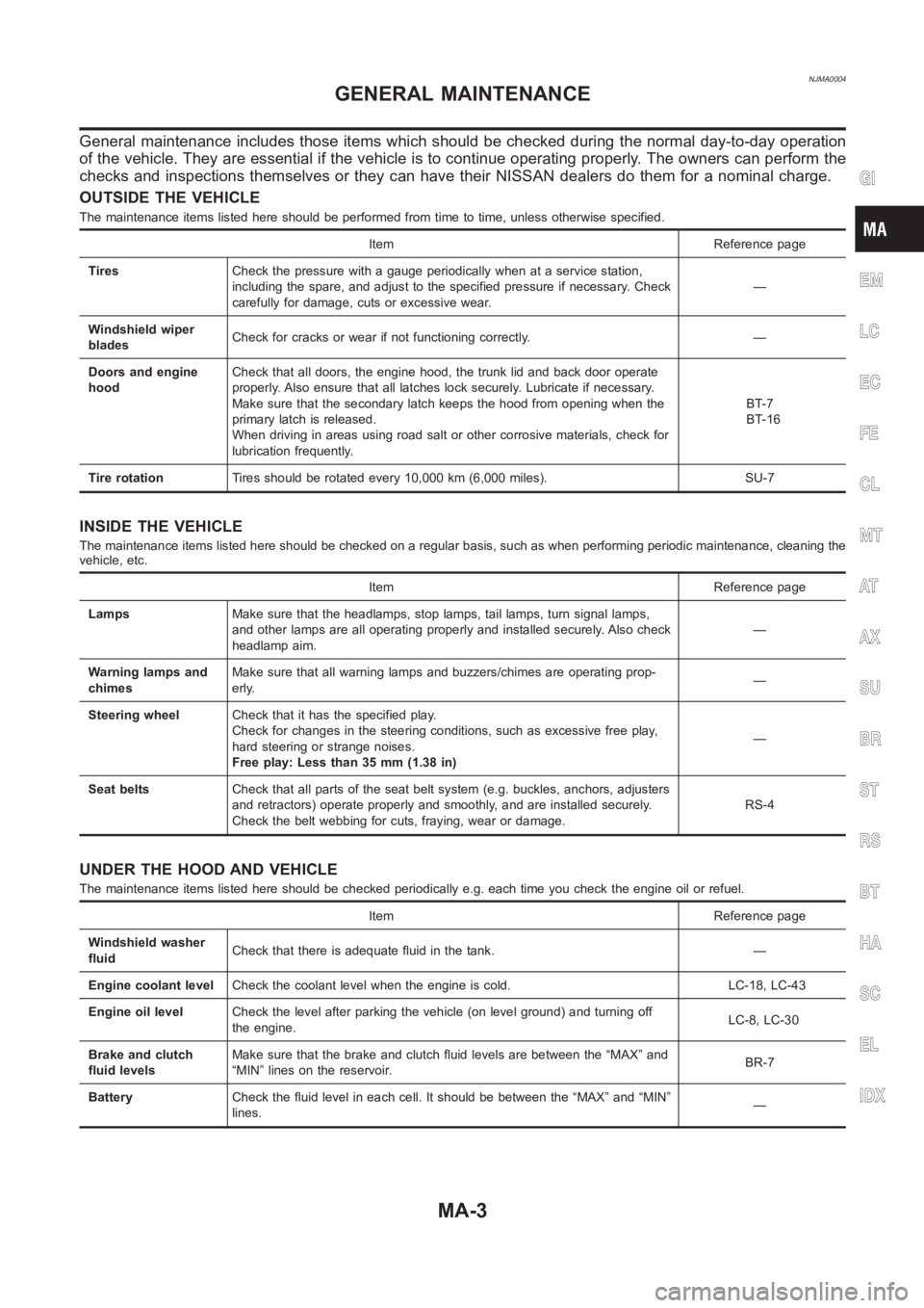
General maintenance includes those items which should be checked during the normal day-to-day operation
of the vehicle. They are essential if the vehicle is to continue operating properly. The owners can perform the
checks and inspections themselves or they can have their NISSAN dealers dothem for a nominal charge.
OUTSIDE THE VEHICLE
The maintenance items listed here should be performed from time to time, unless otherwise specified.
Item Reference page
TiresCheck the pressure with a gauge periodically when at a service station,
including the spare, and adjust to the specified pressure if necessary. Check
carefully for damage, cuts or excessive wear.—
Windshield wiper
bladesCheck for cracks or wear if not functioning correctly. —
Doors and engine
hoodCheck that all doors, the engine hood, the trunk lid and back door operate
properly. Also ensure that all latches lock securely. Lubricate if necessary.
Make sure that the secondary latch keeps the hood from opening when the
primary latch is released.
When driving in areas using road salt or other corrosive materials, check for
lubrication frequently.BT-7
BT-16
Tire rotationTires should be rotated every 10,000 km (6,000 miles). SU-7
INSIDE THE VEHICLE
The maintenance items listed here should be checked on a regular basis, such as when performing periodic maintenance, cleaning the
vehicle, etc.
Item Reference page
LampsMake sure that the headlamps, stop lamps, tail lamps, turn signal lamps,
and other lamps are all operating properly and installed securely. Also check
headlamp aim.—
Warning lamps and
chimesMake sure that all warning lamps and buzzers/chimes are operating prop-
erly.—
Steering wheelCheck that it has the specified play.
Check for changes in the steering conditions, such as excessive free play,
hard steering or strange noises.
Free play: Less than 35 mm (1.38 in)—
Seat beltsCheck that all parts of the seat belt system (e.g. buckles, anchors, adjusters
and retractors) operate properly and smoothly, and are installed securely.
Check the belt webbing for cuts, fraying, wear or damage.RS-4
UNDER THE HOOD AND VEHICLE
The maintenance items listed here should be checked periodically e.g. each time you check the engine oil or refuel.
Item Reference page
Windshield washer
fluidCheck that there is adequate fluid in the tank. —
Engine coolant levelCheck the coolant level when the engine is cold. LC-18, LC-43
Engine oil levelCheck the level after parking the vehicle (on level ground) and turning off
the engine.LC-8, LC-30
Brake and clutch
fluid levelsMake sure that the brake and clutch fluid levels are between the “MAX” and
“MIN” lines on the reservoir.BR-7
BatteryCheck the fluid level in each cell. It should be between the “MAX” and “MIN”
lines.—
GI
EM
LC
EC
FE
CL
MT
AT
AX
SU
BR
ST
RS
BT
HA
SC
EL
IDX
GENERAL MAINTENANCE
MA-3
Page 429 of 3189
![NISSAN ALMERA N16 2003 Electronic Repair Manual TROUBLE DIAGNOSIS
EC-99
[QG (WITH EURO-OBD)]
C
D
E
F
G
H
I
J
K
L
MA
EC
5. Perform each diagnostic mode according to each service proce-
dure.
For further information, see the GST Operation Manu NISSAN ALMERA N16 2003 Electronic Repair Manual TROUBLE DIAGNOSIS
EC-99
[QG (WITH EURO-OBD)]
C
D
E
F
G
H
I
J
K
L
MA
EC
5. Perform each diagnostic mode according to each service proce-
dure.
For further information, see the GST Operation Manu](/manual-img/5/57350/w960_57350-428.png)
TROUBLE DIAGNOSIS
EC-99
[QG (WITH EURO-OBD)]
C
D
E
F
G
H
I
J
K
L
MA
EC
5. Perform each diagnostic mode according to each service proce-
dure.
For further information, see the GST Operation Manual of the
tool maker.
CONSULT-II Reference Value in Data Monitor ModeEBS00K3W
Remarks:
● Specification data are reference values.
● Specification data are output/input values which are detected or supplied by the ECM at the connector.
* Specification data may not be directly related to their components signals/values/operations.
i.e. Adjust ignition timing with a timing light before monitoring IGN TIMING, because the monitor may show the specification data in
spite of the ignition timing not being adjusted to the specification data. This IGN TIMING monitors the data calculated by the ECM
according to the signals input from the camshaft position sensor and other ignition timing related sensors.
SEF416S
MONITOR ITEM CONDITION SPECIFICATION
ENG SPEED
●Tachometer: Connect
●Run engine and compare tachometer indication with the CONSULT-II
value.Almost the same speed as the
CONSULT-II value.
MAS A/F SE-B1
●Engine: After warming up
●Air conditioner switch: OFF
●Shift lever:
N (A/T models)
Neutral (M/T models)
●No-loadIdle Approx. 1.0 - 1.7V
2,500 rpm Approx. 1.5 - 2.1V
B/FUEL SCHDL
●Engine: After warming up
●Shift lever:
N (A/T models)
Neutral (M/T models)
●Air conditioner switch: OFF
●No-loadIdle 1.5 - 3.0 msec
2,000 rpm 1.2 - 3.0 msec
A/F ALPHA-B1
●Engine: After warming upMaintaining engine speed at 2,000
rpm75% - 125%
COOLAN TEMP/S
●Engine: After warming up More than 70°C (158°F)
HO2S1 (B1)
●Engine: After warming upMaintaining engine speed at 2,000
rpm0 - 0.3V ←→ Approx. 0.6 - 1.0V
HO2S2 (B1)
●Engine: After warming up
●Keeping the engine speed
between 3,500 and 4,000 rpm
for one minute and at idle for
one minute under no loadRevving engine from idle to 3,000
rpm quickly.0 - 0.3V ←→ Approx. 0.6 - 1.0V
HO2S1 MNTR (B1)
●Engine: After warming upMaintaining engine speed at 2,000
rpmLEAN←→ RICH
Changes more than 5 times dur-
ing 10 seconds.
HO2S2 MNTR (B1)
●Engine: After warming up
●Keeping the engine speed
between 3,500 and 4,000 rpm
for one minute and at idle for
one minute under no loadRevving engine from idle to 3,000
rpm quickly.LEAN←→ RICH
VEH SPEED SE
●Turn drive wheels and compare speedometer indication with the CON-
SULT-II value.Almost the same speed as the
CONSULT-II value
BATTERY VOLT
●Ignition switch: ON (Engine stopped) 11 - 14V
Page 432 of 3189
![NISSAN ALMERA N16 2003 Electronic Repair Manual EC-102
[QG (WITH EURO-OBD)]
TROUBLE DIAGNOSIS
*: Accelerator pedal position sensor 2 signal and throttle position sensor 2 signal are converted by ECM internally. Thus, they differ from
ECM terminals NISSAN ALMERA N16 2003 Electronic Repair Manual EC-102
[QG (WITH EURO-OBD)]
TROUBLE DIAGNOSIS
*: Accelerator pedal position sensor 2 signal and throttle position sensor 2 signal are converted by ECM internally. Thus, they differ from
ECM terminals](/manual-img/5/57350/w960_57350-431.png)
EC-102
[QG (WITH EURO-OBD)]
TROUBLE DIAGNOSIS
*: Accelerator pedal position sensor 2 signal and throttle position sensor 2 signal are converted by ECM internally. Thus, they differ from
ECM terminals voltage signal.
Major Sensor Reference Graph in Data Monitor ModeEBS00K3X
The following are the major sensor reference graphs in “DATA MONITOR” mode.
CLSD THL POS, ACCEL SEN 1, THRTL SEN 1
Below is the data for “CLSD THL POS”, “ACCEL SEN 1” and “THRTL SEN 1” when depressing the accelera-
tor pedal with the ignition switch “ON” and with selector lever in “D” position (A/T models) or with shift lever in
“1st” position (M/T models).
The signal of “ACCEL SEN 1” and “THRTL SEN 1” should rise gradually without any intermittent drop or rise
after “CLSD THL POS” is changed from “ON” to “OFF”.
ENG SPEED, MAS A/F SE-B1, THRTL SEN 1, HO2S2 (B1), HO2S1 (B1), INJ PULSE-B1
Below is the data for “ENG SPEED”, “MAS A/F SE-B1”, “THRTL SEN 1”, “HO2S2 (B1)”, “HO2S1 (B1)” and
“INJ PULSE-B1” when revving engine quickly up to 4,800 rpm under no load after warming up engine suffi-
ciently.
AC PRESS SEN
●Ignition switch: ON (Engine stopped) Approx. 0V
●Engine: Idle
●Air conditioner switch: OFF1.0 - 4.0V
VEH SPEED SE
●Turn drive wheels and compare speedometer indication with the CON-
SULT-II value.Almost the same speed as the
CONSULT-II value
CAN COMM
●Ignition switch: ONOK
CAN CIRC 1OK
CAN CIRC 2OK or UNKWN
CAN CIRC 3UNKWN
CAN CIRC 4OK
CAN CIRC 5UNKWN
CAN CIRC 6OK
CAN CIRC 7UNKWN MONITOR ITEM CONDITION SPECIFICATION
PBIB0198E
Page 555 of 3189
![NISSAN ALMERA N16 2003 Electronic Repair Manual DTC P0300 - P0304 MULTIPLE CYLINDER MISFIRE, NO. 1 - 4 CYLINDER MIS-
FIRE
EC-225
[QG (WITH EURO-OBD)]
C
D
E
F
G
H
I
J
K
L
MA
EC
DTC P0300 - P0304 MULTIPLE CYLINDER MISFIRE, NO. 1 - 4 CYLIND NISSAN ALMERA N16 2003 Electronic Repair Manual DTC P0300 - P0304 MULTIPLE CYLINDER MISFIRE, NO. 1 - 4 CYLINDER MIS-
FIRE
EC-225
[QG (WITH EURO-OBD)]
C
D
E
F
G
H
I
J
K
L
MA
EC
DTC P0300 - P0304 MULTIPLE CYLINDER MISFIRE, NO. 1 - 4 CYLIND](/manual-img/5/57350/w960_57350-554.png)
DTC P0300 - P0304 MULTIPLE CYLINDER MISFIRE, NO. 1 - 4 CYLINDER MIS-
FIRE
EC-225
[QG (WITH EURO-OBD)]
C
D
E
F
G
H
I
J
K
L
MA
EC
DTC P0300 - P0304 MULTIPLE CYLINDER MISFIRE, NO. 1 - 4 CYLINDER MIS-
FIRE
PFP:00000
On Board Diagnosis LogicEBS00K7U
When a misfire occurs, engine speed will fluctuate. If the engine speed fluctuates enough to cause the crank-
shaft position (CKP) sensor (POS) signal to vary, ECM can determine that a misfire is occurring.
The misfire detection logic consists of the following two conditions.
1. One Trip Detection Logic (Three Way Catalyst Damage)
On the first trip that a misfire condition occurs that can damage the three way catalyst (TWC) due to over-
heating, the MI will blink.
When a misfire condition occurs, the ECM monitors the CKP sensor (POS) signal every 200 engine revo-
lutions for a change.
When the misfire condition decreases to a level that will not damage the TWC, the MI will turn off.
If another misfire condition occurs that can damage the TWC on a second trip, the MI will blink.
When the misfire condition decreases to a level that will not damage the TWC, the MI will remain on.
If another misfire condition occurs that can damage the TWC, the MI will begin to blink again.
2. Two Trip Detection Logic (Exhaust quality deterioration)
For misfire conditions that will not damage the TWC (but will affect vehicle emissions), the MI will only light
when the misfire is detected on a second trip. During this condition, the ECM monitors the CKP sensor
signal every 1,000 engine revolutions.
A misfire malfunction can be detected on any one cylinder or on multiple cylinders.
DTC Confirmation ProcedureEBS00K7V
CAUTION:
Always drive vehicle at a safe speed.
NOTE:
If “DTC Confirmation Procedure” has been previously conducted, always turn ignition switch “OFF” and wait at
least 10 seconds before conducting the next test.
Sensor Input Signal to ECM ECM function
Crankshaft position sensor (POS) Engine speed On board diagnosis of misfire
DTC No. Trouble diagnosis name DTC detecting condition Possible cause
P0300
0300Multiple cylinder misfire
detectedMultiple cylinder misfire.
●Improper spark plug
●Insufficient compression
●Incorrect fuel pressure
●The injector circuit is open or shorted
●Fuel injectors
●Intake air leak
●The ignition signal circuit is open or
shorted
●Lack of fuel
●Drive plate or flywheel
●Heated oxygen sensor 1
●Incorrect PCV hose connection P0301
0301No.1 cylinder misfire
detectedNo. 1 cylinder misfires.
P0302
0302No. 2 cylinder misfire
detectedNo. 2 cylinder misfires.
P0303
0303No. 3 cylinder misfire
detectedNo. 3 cylinder misfires.
P0304
0304No. 4 cylinder misfire
detectedNo. 4 cylinder misfires.
Page 806 of 3189
![NISSAN ALMERA N16 2003 Electronic Repair Manual EC-476
[QG (WITHOUT EURO-OBD)]
TROUBLE DIAGNOSIS
MAS A/F SE-B1
●Engine: After warming up
●Air conditioner switch: OFF
●Shift lever:
N (A/T models)
Neutral (M/T models)
●No-loadIdle Approx. 1.0 NISSAN ALMERA N16 2003 Electronic Repair Manual EC-476
[QG (WITHOUT EURO-OBD)]
TROUBLE DIAGNOSIS
MAS A/F SE-B1
●Engine: After warming up
●Air conditioner switch: OFF
●Shift lever:
N (A/T models)
Neutral (M/T models)
●No-loadIdle Approx. 1.0](/manual-img/5/57350/w960_57350-805.png)
EC-476
[QG (WITHOUT EURO-OBD)]
TROUBLE DIAGNOSIS
MAS A/F SE-B1
●Engine: After warming up
●Air conditioner switch: OFF
●Shift lever:
N (A/T models)
Neutral (M/T models)
●No-loadIdle Approx. 1.0 - 1.7V
2,500 rpm Approx. 1.5 - 2.1V
B/FUEL SCHDL
●Engine: After warming up
●Shift lever:
N (A/T models)
Neutral (M/T models)
●Air conditioner switch: OFF
●No-loadIdle 1.5 - 3.0 msec
2,000 rpm 1.2 - 3.0 msec
A/F ALPHA-B1
●Engine: After warming upMaintaining engine speed at 2,000
rpm75% - 125%
COOLAN TEMP/S
●Engine: After warming up More than 70°C (158°F)
HO2S1 (B1)
●Engine: After warming upMaintaining engine speed at 2,000
rpm0 - 0.3V ←→ Approx. 0.6 - 1.0V
HO2S2 (B1)
●Engine: After warming up
●Keeping the engine speed
between 3,500 and 4,000 rpm
for one minute and at idle for
one minute under no loadRevving engine from idle to 3,000
rpm quickly.0 - 0.3V ←→ Approx. 0.6 - 1.0V
HO2S1 MNTR (B1)
●Engine: After warming upMaintaining engine speed at 2,000
rpmLEAN ←→ RICH
Changes more than 5 times dur-
ing 10 seconds.
HO2S2 MNTR (B1)
●Engine: After warming up
●Keeping the engine speed
between 3,500 and 4,000 rpm
for one minute and at idle for
one minute under no loadRevving engine from idle to 3,000
rpm quickly.LEAN ←→ RICH
VEH SPEED SE
●Turn drive wheels and compare speedometer indication with the CON-
SULT-II value.Almost the same speed as the
CONSULT-II value
BATTERY VOLT
●Ignition switch: ON (Engine stopped) 11 - 14V
ACCEL SEN1
ACCEL SEN2*
●Ignition switch: ON
(engine stopped)Accelerator pedal: Fully released 0.35 - 0.67V
Accelerator pedal: Fully depressed More than 3.9V
THRTL SEN1
THRTL SEN2*
●Ignition switch: ON
(engine stopped)Accelerator pedal: Fully released More than 0.36V
●Shift lever:
D (A/T model)
1st (M/T model)Accelerator pedal: Fully depressed Less than 4.75V
START SIGNAL
●Ignition switch: ON → START → ON OFF → ON → OFF
CLSD THL POS
●Ignition switch: ON
(engine stopped)Accelerator pedal: Fully released ON
Accelerator pedal: Slightly depressed OFF
AIR COND SIG
●Engine: After warming up, idle
the engineAir conditioner switch: OFF OFF
Air conditioner switch: ON
(Compressor operates.)ON
P/N POSI SW
●Ignition switch: ONShift lever: P or N (A/T models)
Neutral (M/T models)ON
Shift lever: Except above OFF MONITOR ITEM CONDITION SPECIFICATION
Page 1172 of 3189

SEF437Y
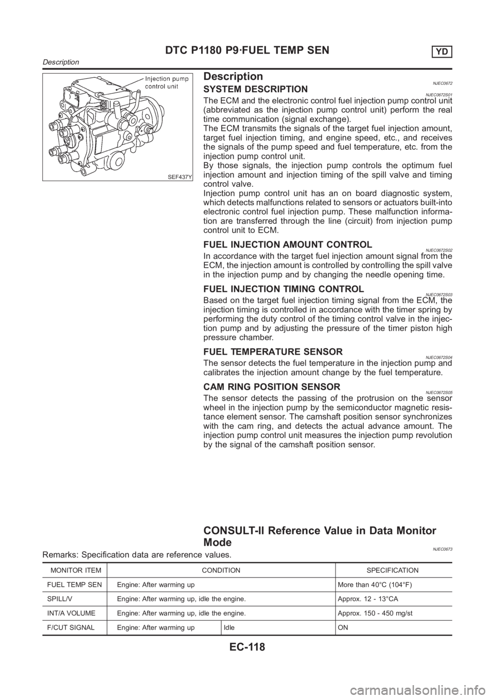
DescriptionNJEC0672SYSTEM DESCRIPTIONNJEC0672S01The ECM and the electronic control fuel injection pump control unit
(abbreviated as the injection pump control unit) perform the real
time communication (signal exchange).
The ECM transmits the signals of the target fuel injection amount,
target fuel injection timing, and engine speed, etc., and receives
the signals of the pump speed and fuel temperature, etc. from the
injection pump control unit.
By those signals, the injection pump controls the optimum fuel
injection amount and injection timing of the spill valve and timing
control valve.
Injection pump control unit has an on board diagnostic system,
which detects malfunctions related to sensors or actuators built-into
electronic control fuel injection pump. These malfunction informa-
tion are transferred through the line (circuit) from injection pump
control unit to ECM.
FUEL INJECTION AMOUNT CONTROLNJEC0672S02In accordance with the target fuel injection amount signal from the
ECM, the injection amount is controlled by controlling the spill valve
in the injection pump and by changing the needle opening time.
FUEL INJECTION TIMING CONTROLNJEC0672S03Based on the target fuel injection timing signal from the ECM, the
injection timing is controlled in accordance with the timer spring by
performing the duty control of the timing control valve in the injec-
tion pump and by adjusting the pressure of the timer piston high
pressure chamber.
FUEL TEMPERATURE SENSORNJEC0672S04The sensor detects the fuel temperature in the injection pump and
calibrates the injection amount change by the fuel temperature.
CAM RING POSITION SENSORNJEC0672S05The sensor detects the passing of the protrusion on the sensor
wheel in the injection pump by the semiconductor magnetic resis-
tance element sensor. The camshaft position sensor synchronizes
with the cam ring, and detects the actual advance amount. The
injection pump control unit measures the injection pump revolution
by the signal of the camshaft position sensor.
CONSULT-II Reference Value in Data Monitor
Mode
NJEC0673Remarks: Specification data are reference values.
MONITOR ITEM CONDITION SPECIFICATION
FUEL TEMP SEN Engine: After warming up More than 40°C (104°F)
SPILL/V Engine: After warming up, idle the engine. Approx. 12 - 13°CA
INT/A VOLUME Engine: After warming up, idle the engine. Approx. 150 - 450 mg/st
F/CUT SIGNAL Engine: After warming up Idle ON
DTC P1180 P9·FUEL TEMP SENYD
Description
EC-118
Page 1178 of 3189

SEF437Y
DescriptionNJEC0753SYSTEM DESCRIPTIONNJEC0753S01The ECM and the electronic control fuel injection pump control unit
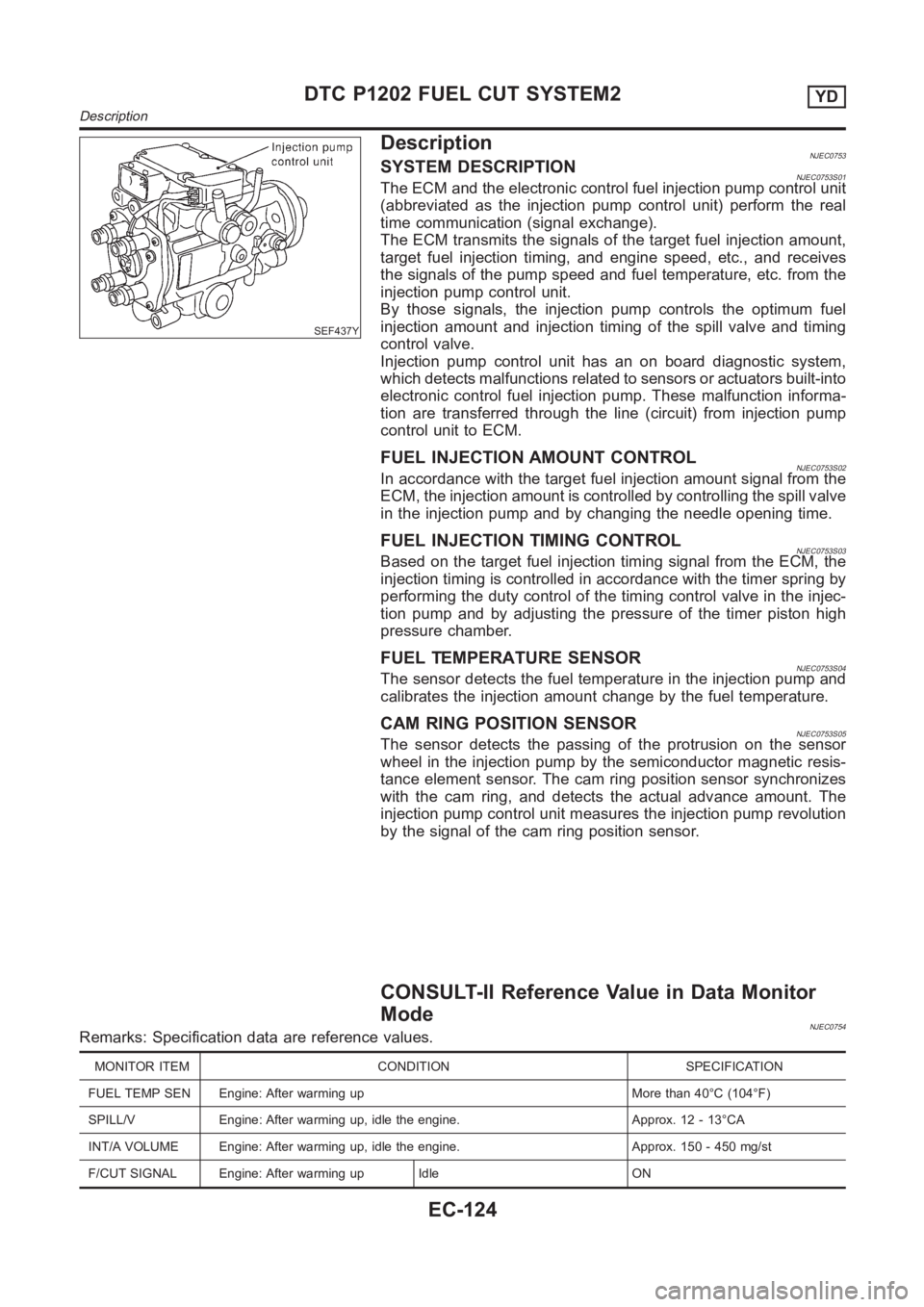
(abbreviated as the injection pump control unit) perform the real
time communication (signal exchange).
The ECM transmits the signals of the target fuel injection amount,
target fuel injection timing, and engine speed, etc., and receives
the signals of the pump speed and fuel temperature, etc. from the
injection pump control unit.
By those signals, the injection pump controls the optimum fuel
injection amount and injection timing of the spill valve and timing
control valve.
Injection pump control unit has an on board diagnostic system,
which detects malfunctions related to sensors or actuators built-into
electronic control fuel injection pump. These malfunction informa-
tion are transferred through the line (circuit) from injection pump
control unit to ECM.
FUEL INJECTION AMOUNT CONTROLNJEC0753S02In accordance with the target fuel injection amount signal from the
ECM, the injection amount is controlled by controlling the spill valve
in the injection pump and by changing the needle opening time.
FUEL INJECTION TIMING CONTROLNJEC0753S03Based on the target fuel injection timing signal from the ECM, the
injection timing is controlled in accordance with the timer spring by
performing the duty control of the timing control valve in the injec-
tion pump and by adjusting the pressure of the timer piston high
pressure chamber.
FUEL TEMPERATURE SENSORNJEC0753S04The sensor detects the fuel temperature in the injection pump and
calibrates the injection amount change by the fuel temperature.
CAM RING POSITION SENSORNJEC0753S05The sensor detects the passing of the protrusion on the sensor
wheel in the injection pump by the semiconductor magnetic resis-
tance element sensor. The cam ring position sensor synchronizes
with the cam ring, and detects the actual advance amount. The
injection pump control unit measures the injection pump revolution
by the signal of the cam ring position sensor.
CONSULT-II Reference Value in Data Monitor
Mode
NJEC0754Remarks: Specification data are reference values.
MONITOR ITEM CONDITION SPECIFICATION
FUEL TEMP SEN Engine: After warming up More than 40°C (104°F)
SPILL/V Engine: After warming up, idle the engine. Approx. 12 - 13°CA
INT/A VOLUME Engine: After warming up, idle the engine. Approx. 150 - 450 mg/st
F/CUT SIGNAL Engine: After warming up Idle ON
DTC P1202 FUEL CUT SYSTEM2YD
Description
EC-124
Page 1199 of 3189

SEF437Y
DescriptionNJEC0727SYSTEM DESCRIPTIONNJEC0727S01The ECM and the electronic control fuel injection pump control unit
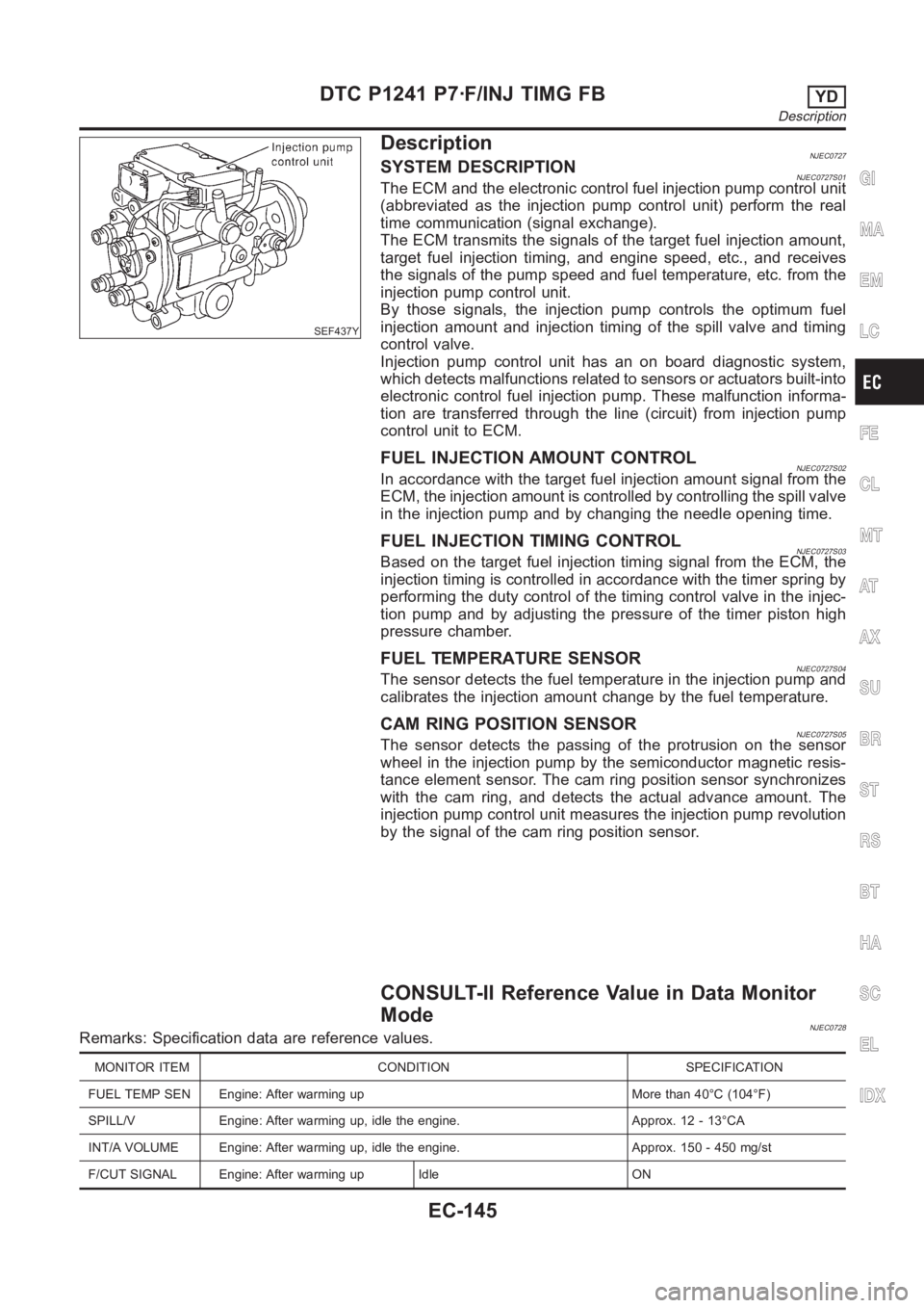
(abbreviated as the injection pump control unit) perform the real
time communication (signal exchange).
The ECM transmits the signals of the target fuel injection amount,
target fuel injection timing, and engine speed, etc., and receives
the signals of the pump speed and fuel temperature, etc. from the
injection pump control unit.
By those signals, the injection pump controls the optimum fuel
injection amount and injection timing of the spill valve and timing
control valve.
Injection pump control unit has an on board diagnostic system,
which detects malfunctions related to sensors or actuators built-into
electronic control fuel injection pump. These malfunction informa-
tion are transferred through the line (circuit) from injection pump
control unit to ECM.
FUEL INJECTION AMOUNT CONTROLNJEC0727S02In accordance with the target fuel injection amount signal from the
ECM, the injection amount is controlled by controlling the spill valve
in the injection pump and by changing the needle opening time.
FUEL INJECTION TIMING CONTROLNJEC0727S03Based on the target fuel injection timing signal from the ECM, the
injection timing is controlled in accordance with the timer spring by
performing the duty control of the timing control valve in the injec-
tion pump and by adjusting the pressure of the timer piston high
pressure chamber.
FUEL TEMPERATURE SENSORNJEC0727S04The sensor detects the fuel temperature in the injection pump and
calibrates the injection amount change by the fuel temperature.
CAM RING POSITION SENSORNJEC0727S05The sensor detects the passing of the protrusion on the sensor
wheel in the injection pump by the semiconductor magnetic resis-
tance element sensor. The cam ring position sensor synchronizes
with the cam ring, and detects the actual advance amount. The
injection pump control unit measures the injection pump revolution
by the signal of the cam ring position sensor.
CONSULT-II Reference Value in Data Monitor
Mode
NJEC0728Remarks: Specification data are reference values.
MONITOR ITEM CONDITION SPECIFICATION
FUEL TEMP SEN Engine: After warming up More than 40°C (104°F)
SPILL/V Engine: After warming up, idle the engine. Approx. 12 - 13°CA
INT/A VOLUME Engine: After warming up, idle the engine. Approx. 150 - 450 mg/st
F/CUT SIGNAL Engine: After warming up Idle ON
GI
MA
EM
LC
FE
CL
MT
AT
AX
SU
BR
ST
RS
BT
HA
SC
EL
IDX
DTC P1241 P7·F/INJ TIMG FBYD
Description
EC-145