2003 NISSAN ALMERA N16 Electrical systems
[x] Cancel search: Electrical systemsPage 1 of 3189
Edition: August 2003
Release: October 2003 (01)
Publication No.: SM3E00-1N16E1E
Reference No.: 7711347018
GENERAL INFORMATIONGI
MAINTENANCEMA
ENGINE MECHANICAL – QGEM-QG
ENGINE MECHANICAL – YDEM-YD
ENGINE LUBRICATION &
COOLING SYSTEMSLC
ENGINE CONTROL SYSTEM – QGEC - QG
ENGINE CONTROL SYSTEM – YDEC - YD
ACCELERATOR CONTROL,
FUEL & EXHAUST SYSTEMSFE
CLUTCHCL
MANUAL TRANSAXLEMT
AUTOMATIC TRANSAXLEAT
FRONT & REAR AXLEAX
FRONT & REAR SUSPENSIONSU
BRAKE SYSTEMBR
STEERING SYSTEMST
RESTRAINT SYSTEMRS
BODY & TRIMBT
HEATER & MANUAL AIR CONDITIONERHA
AUTOMATIC AIR CONDITIONERATC
STARTING & CHARGING SYSTEMSSC
ELECTRICAL SYSTEMEL
ALPHABETICAL INDEXIDX
ALMERA
MODEL N16 SERIES
NISSAN EUROPE S.A.S.
© 2003 NISSAN EUROPE S.A.S.
Produced in The Netherlands
Not to be reproduced in whole or in part
without the prior written permission of
Nissan Europe S.A.S., Paris, France.
QUICK REFERENCE INDEX
Page 7 of 3189
SEF289H
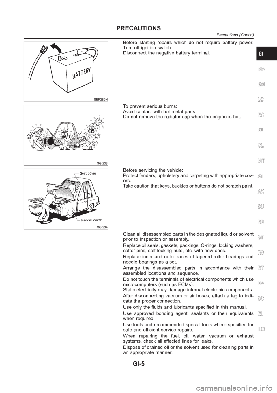
Before starting repairs which do not require battery power:
Turn off ignition switch.
Disconnect the negative battery terminal.
SGI233
To prevent serious burns:
Avoid contact with hot metal parts.
Do not remove the radiator cap when the engine is hot.
SGI234
Before servicing the vehicle:
Protect fenders, upholstery and carpeting with appropriate cov-
ers.
Take caution that keys, buckles or buttons do not scratch paint.
Clean all disassembled parts in the designated liquid or solvent
prior to inspection or assembly.
Replace oil seals, gaskets, packings, O-rings, locking washers,
cotter pins, self-locking nuts, etc. with new ones.
Replace inner and outer races of tapered roller bearings and
needle bearings as a set.
Arrange the disassembled parts in accordance with their
assembled locations and sequence.
Do not touch the terminals of electrical components which use
microcomputers (such as ECMs).
Static electricity may damage internal electronic components.
After disconnecting vacuum or air hoses, attach a tag to indi-
cate the proper connection.
Use only the fluids and lubricants specified in this manual.
Use approved bonding agent, sealants or their equivalents
when required.
Use tools and recommended special tools where specified for
safe and efficient service repairs.
When repairing the fuel, oil, water, vacuum or exhaust
systems, check all affected lines for leaks.
Dispose of drained oil or the solvent used for cleaning parts in
an appropriate manner.
MA
EM
LC
EC
FE
CL
MT
AT
AX
SU
BR
ST
RS
BT
HA
SC
EL
IDX
PRECAUTIONS
Precautions (Cont’d)
GI-5
Page 31 of 3189
strand will have a high resistance to the current. This will be picked
up as a slight voltage drop.
Unwanted resistance can be caused by many situations as follows:
Undersized wiring (single strand example)
Corrosion on switch contacts
Loose wire connections or splices.
If repairs are needed always use wire that is of the same or larger
gauge.
Measuring Voltage Drop — Accumulated Method
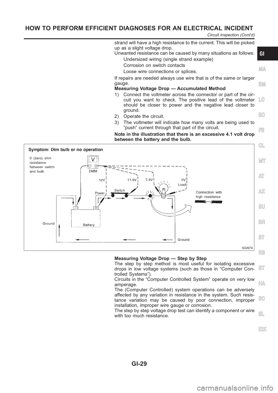
1) Connect the voltmeter across the connector or part of the cir-
cuit you want to check. The positive lead of the voltmeter
should be closer to power and the negative lead closer to
ground.
2) Operate the circuit.
3) The voltmeter will indicate how many volts are being used to
“push” current through that part of the circuit.
Note in the illustration that there is an excessive 4.1 volt drop
between the battery and the bulb.
SGI974
Measuring Voltage Drop — Step by Step
The step by step method is most useful for isolating excessive
drops in low voltage systems (such as those in “Computer Con-
trolled Systems”).
Circuits in the “Computer Controlled System” operate on very low
amperage.
The (Computer Controlled) system operations can be adversely
affected by any variation in resistance in the system. Such resis-
tance variation may be caused by poor connection, improper
installation, improper wire gauge or corrosion.
The step by step voltage drop test can identify a component or wire
with too much resistance.
MA
EM
LC
EC
FE
CL
MT
AT
AX
SU
BR
ST
RS
BT
HA
SC
EL
IDX
HOW TO PERFORM EFFICIENT DIAGNOSES FOR AN ELECTRICAL INCIDENT
Circuit Inspection (Cont’d)
GI-29
Page 345 of 3189
![NISSAN ALMERA N16 2003 Electronic Repair Manual PRECAUTIONS
EC-15
[QG (WITH EURO-OBD)]
C
D
E
F
G
H
I
J
K
L
MA
EC
PRECAUTIONSPFP:00001
Precautions for Supplemental Restraint System (SRS) “AIR BAG” and “SEAT
BELT PRE-TENSIONER”
EBS00K2V
The](/manual-img/5/57350/w960_57350-344.png "NISSAN ALMERA N16 2003 Electronic Repair Manual PRECAUTIONS
EC-15
[QG (WITH EURO-OBD)]
C
D
E
F
G
H
I
J
K
L
MA
EC
PRECAUTIONSPFP:00001
Precautions for Supplemental Restraint System (SRS) “AIR BAG” and “SEAT
BELT PRE-TENSIONER”
EBS00K2V
The")
PRECAUTIONS
EC-15
[QG (WITH EURO-OBD)]
C
D
E
F
G
H
I
J
K
L
MA
EC
PRECAUTIONSPFP:00001
Precautions for Supplemental Restraint System (SRS) “AIR BAG” and “SEAT
BELT PRE-TENSIONER”
EBS00K2V
The Supplemental Restraint System such as “AIR BAG” and “SEAT BELT PRE-TENSIONER”, used along
with a front seat belt, helps to reduce the risk or severity of injury to the driver and front passenger for certain
types of collision. Information necessary to service the system safely is included in the SRS and SB section of
this Service Manual.
WARNING:
●To avoid rendering the SRS inoperative, which could increase the risk of personal injury or death
in the event of a collision which would result in air bag inflation, all maintenance must be per-
formed by an authorized NISSAN/INFINITI dealer.
●Improper maintenance, including incorrect removal and installation of the SRS, can lead to per-
sonal injury caused by unintentional activation of the system. For removal of Spiral Cable and Air
Bag Module, see the SRS section.
●Do not use electrical test equipment on any circuit related to the SRS unless instructed to in this
Service Manual. SRS wiring harnesses can be identified by yellow and/or orange harness connec-
tors.
On Board Diagnostic (OBD) System of Engine and A/TEBS00K2W
The ECM has an on board diagnostic system. It will light up the malfunction indicator (MI) to warn the driver of
a malfunction causing emission deterioration.
CAUTION:
●Be sure to turn the ignition switch OFF and disconnect the battery ground cable before any repair
or inspection work. The open/short circuit of related switches, sensors, solenoid valves, etc. will
cause the MI to light up.
●Be sure to connect and lock the connectors securely after work. A loose (unlocked) connector will
cause the MI to light up due to the open circuit. (Be sure the connector is free from water, grease,
dirt, bent terminals, etc.)
●Certain systems and components, especially those related to OBD, may use a new style slide-
locking type harness connector. For description and how to disconnect, refer to EL-7.
●Be sure to route and secure the harnesses properly after work. The interference of the harness
with a bracket, etc. may cause the MI to light up due to the short circuit.
●Be sure to connect rubber tubes properly after work. A misconnected or disconnected rubber tube
may cause the MI to light up due to the malfunction of the fuel injection system, etc.
●Be sure to erase the unnecessary malfunction information (repairs completed) from the ECM and
TCM (Transmission control module) before returning the vehicle to the customer.
PrecautionEBS00K2X
●Always use a 12 volt battery as power source.
●Do not attempt to disconnect battery cables while engine is
running.
●Before connecting or disconnecting the ECM harness con-
nector, turn ignition switch OFF and disconnect battery
ground cable. Failure to do so may damage the ECM
because battery voltage is applied to ECM even if ignition
switch is turned off.
●Before removing parts, turn ignition switch OFF and then
disconnect battery ground cable.
SEF289H
Page 418 of 3189
![NISSAN ALMERA N16 2003 Electronic Repair Manual EC-88
[QG (WITH EURO-OBD)]
TROUBLE DIAGNOSIS
ENGINE CONTROL COMPONENT PARTS/CONTROL SYSTEMS APPLICATION
X: Applicable
*1: This item includes 1st trip DTCs.
*2: This mode includes 1st trip freeze frame](/manual-img/5/57350/w960_57350-417.png "NISSAN ALMERA N16 2003 Electronic Repair Manual EC-88
[QG (WITH EURO-OBD)]
TROUBLE DIAGNOSIS
ENGINE CONTROL COMPONENT PARTS/CONTROL SYSTEMS APPLICATION
X: Applicable
*1: This item includes 1st trip DTCs.
*2: This mode includes 1st trip freeze frame")
EC-88
[QG (WITH EURO-OBD)]
TROUBLE DIAGNOSIS
ENGINE CONTROL COMPONENT PARTS/CONTROL SYSTEMS APPLICATION
X: Applicable
*1: This item includes 1st trip DTCs.
*2: This mode includes 1st trip freeze frame data or freeze frame data. The items appear on CONSULT-II screen in freeze frame data
mode only if a 1st trip DTC or DTC is detected. For details, refer to EC-40, "
FREEZE FRAME DATA AND 1ST TRIP FREEZE FRAME
DATA" .ItemDIAGNOSTIC TEST MODE
WORK
SUP-
PORTSELF-DIAGNOSTIC
RESULTS
DATA
MONI-
TORDATA
MONI-
TOR
(SPEC)ACTIVE
TESTDTC & SRT
CONFIRMATION
DTC
*1FREEZE
FRAME
DATA
*2
SRT
STATUSDTC
WORK
SUP-
PORT
ENGINE CONTROL COMPONENT PARTS
INPUT
Crankshaft position sensor (POS)××××
Camshaft position sensor (PHASE)××××
Mass air flow sensor×××
Engine coolant temperature sensor×××××
Heated oxygen sensor 1×××××
Heated oxygen sensor 2×××××
Vehicle speed signal××××
Accelerator pedal position sensor×××
Throttle position sensor×××
Intake air temperature sensor××××
Knock sensor×
Refrigerant pressure sensor××
Closed throttle position switch
(accelerator pedal position sensor
signal)××
Air conditioner switch××
Park/neutral position (PNP) switch×××
Stop lamp switch×××
Power steering pressure sensor×××
Battery voltage××
Electrical load signal××
OUTPUT
Injectors×× ×
Power transistor (Ignition timing)×× ×
Throttle control motor relay×××
Throttle control motor×
EVAP canister purge volume con-
trol solenoid valve××××
Air conditioner relay××
Fuel pump relay××××
Cooling fan relay××××
Heated oxygen sensor 1 heater××××
Heated oxygen sensor 2 heater××××
Intake valve timing control solenoid
valve××××
Calculated load value×××
Page 739 of 3189
![NISSAN ALMERA N16 2003 Electronic Repair Manual PRECAUTIONS
EC-409
[QG (WITHOUT EURO-OBD)]
C
D
E
F
G
H
I
J
K
L
MA
EC
PRECAUTIONSPFP:00001
Precautions for Supplemental Restraint System (SRS) “AIR BAG” and “SEAT
BELT PRE-TENSIONER”
EBS00KE2](/manual-img/5/57350/w960_57350-738.png "NISSAN ALMERA N16 2003 Electronic Repair Manual PRECAUTIONS
EC-409
[QG (WITHOUT EURO-OBD)]
C
D
E
F
G
H
I
J
K
L
MA
EC
PRECAUTIONSPFP:00001
Precautions for Supplemental Restraint System (SRS) “AIR BAG” and “SEAT
BELT PRE-TENSIONER”
EBS00KE2")
PRECAUTIONS
EC-409
[QG (WITHOUT EURO-OBD)]
C
D
E
F
G
H
I
J
K
L
MA
EC
PRECAUTIONSPFP:00001
Precautions for Supplemental Restraint System (SRS) “AIR BAG” and “SEAT
BELT PRE-TENSIONER”
EBS00KE2
The Supplemental Restraint System such as “AIR BAG” and “SEAT BELT PRE-TENSIONER”, used along
with a front seat belt, helps to reduce the risk or severity of injury to the driver and front passenger for certain
types of collision. Information necessary to service the system safely is included in the SRS and SB section of
this Service Manual.
WARNING:
●To avoid rendering the SRS inoperative, which could increase the risk of personal injury or death
in the event of a collision which would result in air bag inflation, all maintenance must be per-
formed by an authorized NISSAN/INFINITI dealer.
●Improper maintenance, including incorrect removal and installation of the SRS, can lead to per-
sonal injury caused by unintentional activation of the system. For removal of Spiral Cable and Air
Bag Module, see the SRS section.
●Do not use electrical test equipment on any circuit related to the SRS unless instructed to in this
Service Manual. SRS wiring harnesses can be identified by yellow and/or orange harness connec-
tors.
On Board Diagnostic (OBD) System of EngineEBS00KE3
The ECM has an on board diagnostic system. It will light up the malfunction indicator (MI) to warn the driver of
a malfunction causing emission deterioration.
CAUTION:
●Be sure to turn the ignition switch OFF and disconnect the battery ground cable before any repair
or inspection work. The open/short circuit of related switches, sensors, solenoid valves, etc. will
cause the MI to light up.
●Be sure to connect and lock the connectors securely after work. A loose (unlocked) connector will
cause the MI to light up due to the open circuit. (Be sure the connector is free from water, grease,
dirt, bent terminals, etc.)
●Certain systems and components, especially those related to OBD, may use a new style slide-
locking type harness connector. For description and how to disconnect, refer to EL-7.
●Be sure to route and secure the harnesses properly after work. The interference of the harness
with a bracket, etc. may cause the MI to light up due to the short circuit.
●Be sure to connect rubber tubes properly after work. A misconnected or disconnected rubber tube
may cause the MI to light up due to the malfunction of the fuel injection system, etc.
●Be sure to erase the unnecessary malfunction information (repairs completed) from the ECM
before returning the vehicle to the customer.
PrecautionEBS00KE4
●Always use a 12 volt battery as power source.
●Do not attempt to disconnect battery cables while engine is
running.
●Before connecting or disconnecting the ECM harness con-
nector, turn ignition switch OFF and disconnect battery
ground cable. Failure to do so may damage the ECM
because battery voltage is applied to ECM even if ignition
switch is turned off.
●Before removing parts, turn ignition switch OFF and then
disconnect battery ground cable.
SEF289H
Page 796 of 3189
![NISSAN ALMERA N16 2003 Electronic Repair Manual EC-466
[QG (WITHOUT EURO-OBD)]
TROUBLE DIAGNOSIS
ENGINE CONTROL COMPONENT PARTS/CONTROL SYSTEMS APPLICATION
X: Applicable
*1: This item includes 1st trip DTCs.
*2: This mode includes 1st trip freeze f](/manual-img/5/57350/w960_57350-795.png "NISSAN ALMERA N16 2003 Electronic Repair Manual EC-466
[QG (WITHOUT EURO-OBD)]
TROUBLE DIAGNOSIS
ENGINE CONTROL COMPONENT PARTS/CONTROL SYSTEMS APPLICATION
X: Applicable
*1: This item includes 1st trip DTCs.
*2: This mode includes 1st trip freeze f")
EC-466
[QG (WITHOUT EURO-OBD)]
TROUBLE DIAGNOSIS
ENGINE CONTROL COMPONENT PARTS/CONTROL SYSTEMS APPLICATION
X: Applicable
*1: This item includes 1st trip DTCs.
*2: This mode includes 1st trip freeze frame data or freeze frame data. The items appear on CONSULT-II screen in freeze frame data
mode only if a 1st trip DTC or DTC is detected. For details, refer to EC-468
.
CONSULT-II INSPECTION PROCEDURE
1. Turn ignition switch OFF.
ItemDIAGNOSTIC TEST MODE
WORK
SUPPORTSELF-DIAGNOSTIC
RESULTS
DATA
MONI-
TORDATA
MONI-
TOR
(SPEC)ACTIVE
TEST DTC*1FREEZE
FRAME
DATA
*2
ENGINE CONTROL COMPONENT PARTS
INPUT
Crankshaft position sensor (POS)××××
Camshaft position sensor (PHASE)×××
Mass air flow sensor×××
Engine coolant temperature sensor×××××
Heated oxygen sensor 1×××
Heated oxygen sensor 2×××
Vehicle speed signal×××
Accelerator pedal position sensor×××
Throttle position sensor×××
Intake air temperature sensor××
Knock sensor×
Refrigerant pressure sensor××
Closed throttle position switch (accelerator
pedal position sensor signal)××
Air conditioner switch××
Park/neutral position (PNP) switch××
Stop lamp switch×××
Power steering pressure sensor××
Battery voltage××
Electrical load signal××
ENGINE CONTROL COMPONENT PARTS
OUTPUT
Injectors×× ×
Power transistor (Ignition timing)×× ×
Throttle control motor relay×××
Throttle control motor×
EVAP canister purge volume control sole-
noid valve×× ×
Air conditioner relay××
Fuel pump relay××××
Cooling fan relay××××
Heated oxygen sensor 1 heater××
Heated oxygen sensor 2 heater××
Intake valve timing control solenoid valve×× ×
Calculated load value×××
Page 1102 of 3189
Basic InspectionNJEC0632Precaution:
Perform Basic Inspection without electrical or mechanical
loads applied;
Headlamp switch is OFF,
On vehicles equipped with daytime light systems, set
lighting switch to the 1st position to light only small
lamps.
Air conditioner switch is OFF,
Rear defogger switch is OFF,
Steering wheel is in the straight-ahead position, etc.
1 INSPECTION START
1. Check service records for any recent repairs that may indicate a relatedincident.
2. Check the current need for scheduled maintenance, especially for fuel filter and air cleaner filter. Refer to MA-4, “Peri-
odic Maintenance”.
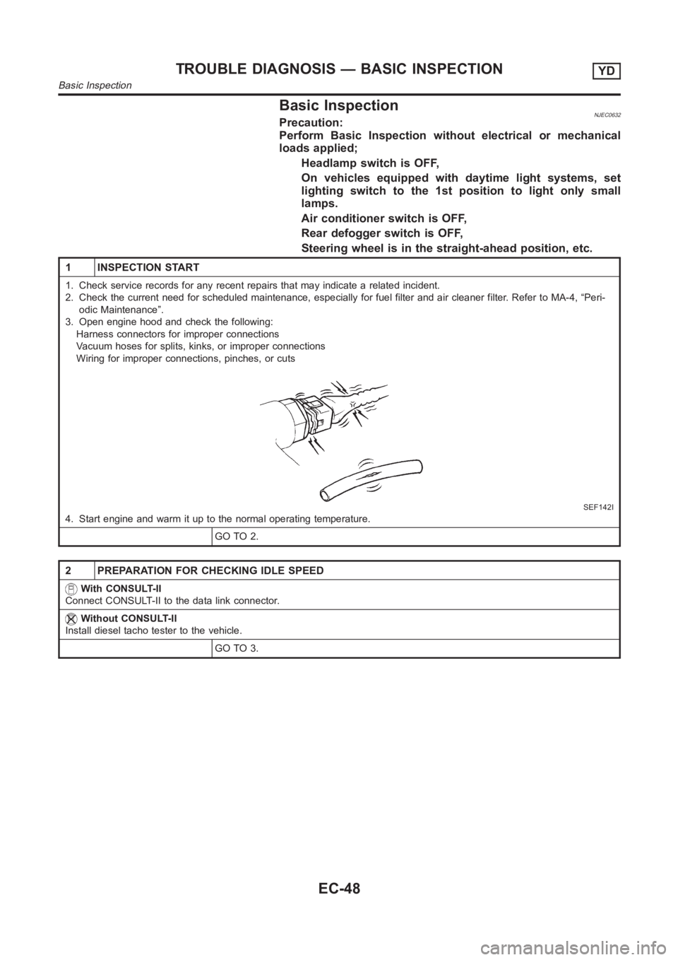
3. Open engine hood and check the following:
Harness connectors for improper connections
Vacuum hoses for splits, kinks, or improper connections
Wiring for improper connections, pinches, or cuts
SEF142I
4. Start engine and warm it up to the normal operating temperature.
GO TO 2.
2 PREPARATION FOR CHECKING IDLE SPEED
With CONSULT-II
Connect CONSULT-II to the data link connector.
Without CONSULT-II
Install diesel tacho tester to the vehicle.
GO TO 3.
TROUBLE DIAGNOSIS — BASIC INSPECTIONYD
Basic Inspection
EC-48