2003 NISSAN ALMERA N16 SHIFT
[x] Cancel search: SHIFTPage 38 of 3189
NJGI0007
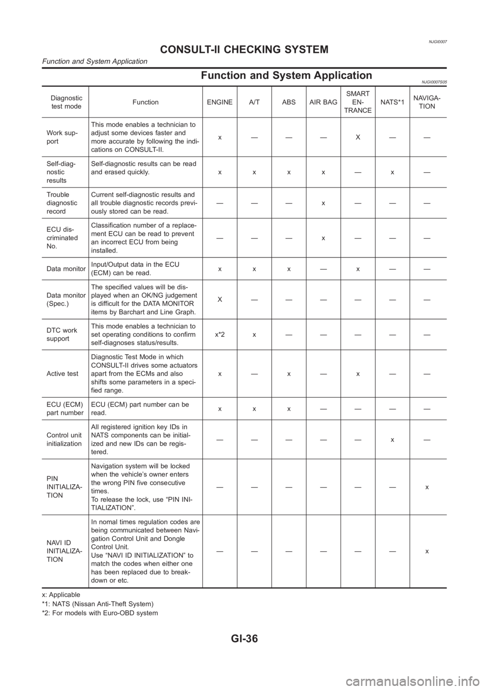
Function and System ApplicationNJGI0007S05
Diagnostic
test modeFunction ENGINE A/T ABS AIR BAGSMART
EN-
TRANCENATS*1NAVIGA-
TION
Work sup-
portThis mode enables a technician to
adjust some devices faster and
more accurate by following the indi-
cations on CONSULT-II.x ———X——
Self-diag-
nostic
resultsSelf-diagnostic results can be read
anderasedquickly. x x x x—x—
Trouble
diagnostic
recordCurrent self-diagnostic results and
all trouble diagnostic records previ-
ously stored can be read.——— x ———
ECU dis-
criminated
No.Classification number of a replace-
ment ECU can be read to prevent
an incorrect ECU from being
installed.——— x ———
Data monitorInput/Output data in the ECU
(ECM) can be read.x x x—x——
Data monitor
(Spec.)The specified values will be dis-
played when an OK/NG judgement
is difficult for the DATA MONITOR
items by Barchart and Line Graph.X ——————
DTC work
supportThis mode enables a technician to
set operating conditions to confirm
self-diagnoses status/results.x*2x —————
Active testDiagnostic Test Mode in which
CONSULT-II drives some actuators
apart from the ECMs and also
shifts some parameters in a speci-
fied range.x—x—x——
ECU (ECM)
part numberECU (ECM) part number can be
read.x x x ————
Control unit
initializationAll registered ignition key IDs in
NATS components can be initial-
ized and new IDs can be regis-
tered.————— x —
PIN
INITIALIZA-
TIONNavigation system will be locked
when the vehicle’s owner enters
the wrong PIN five consecutive
times.
To release the lock, use “PIN INI-
TIALIZATION”.—————— x
NAVI ID
INITIALIZA-
TIONIn nomal times regulation codes are
being communicated between Navi-
gation Control Unit and Dongle
Control Unit.
Use “NAVI ID INITIALIZATION” to
match the codes when either one
has been replaced due to break-
down or etc.—————— x
x: Applicable
*1: NATS (Nissan Anti-Theft System)
*2: For models with Euro-OBD system
CONSULT-II CHECKING SYSTEM
Function and System Application
GI-36
Page 58 of 3189
NJMA0036
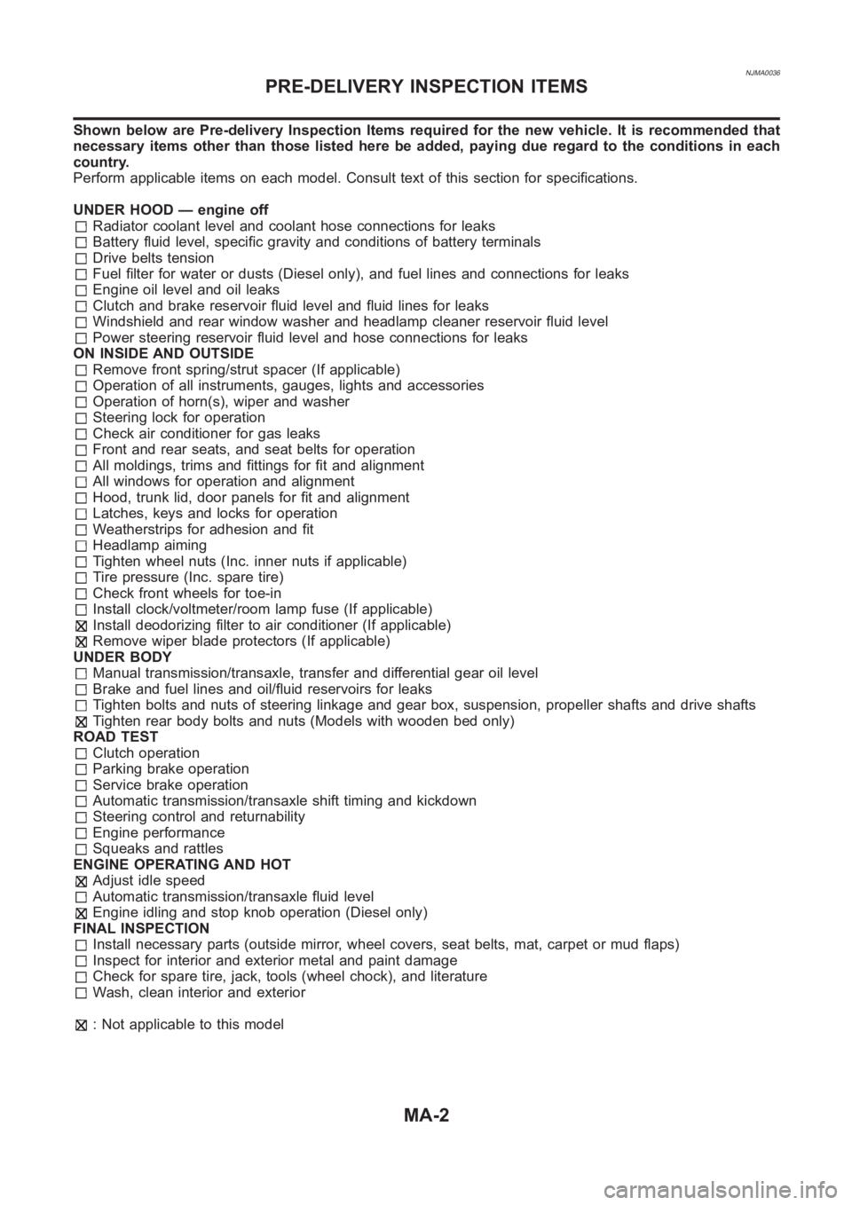
Shown below are Pre-delivery Inspection Items required for the new vehicle. It is recommended that
necessary items other than those listed here be added, paying due regard tothe conditions in each
country.
Perform applicable items on each model. Consult text of this section for specifications.
UNDER HOOD — engine off
Radiator coolant level and coolant hose connections for leaks
Battery fluid level, specific gravity and conditions of battery terminals
Drive belts tension
Fuel filter for water or dusts (Diesel only), and fuel lines and connections for leaks
Engine oil level and oil leaks
Clutch and brake reservoir fluid level and fluid lines for leaks
Windshield and rear window washer and headlamp cleaner reservoir fluid level
Power steering reservoir fluid level and hose connections for leaks
ON INSIDE AND OUTSIDE
Remove front spring/strut spacer (If applicable)
Operation of all instruments, gauges, lights and accessories
Operation of horn(s), wiper and washer
Steering lock for operation
Check air conditioner for gas leaks
Front and rear seats, and seat belts for operation
All moldings, trims and fittings for fit and alignment
All windows for operation and alignment
Hood, trunk lid, door panels for fit and alignment
Latches, keys and locks for operation
Weatherstrips for adhesion and fit
Headlamp aiming
Tighten wheel nuts (Inc. inner nuts if applicable)
Tire pressure (Inc. spare tire)
Check front wheels for toe-in
Install clock/voltmeter/room lamp fuse (If applicable)
Install deodorizing filter to air conditioner (If applicable)
Remove wiper blade protectors (If applicable)
UNDER BODY
Manual transmission/transaxle, transfer and differential gear oil level
Brake and fuel lines and oil/fluid reservoirs for leaks
Tighten bolts and nuts of steering linkage and gear box, suspension, propeller shafts and drive shafts
Tighten rear body bolts and nuts (Models with wooden bed only)
ROAD TEST
Clutch operation
Parking brake operation
Service brake operation
Automatic transmission/transaxle shift timing and kickdown
Steering control and returnability
Engine performance
Squeaks and rattles
ENGINE OPERATING AND HOT
Adjust idle speed
Automatic transmission/transaxle fluid level
Engine idling and stop knob operation (Diesel only)
FINAL INSPECTION
Install necessary parts (outside mirror, wheel covers, seat belts, mat, carpet or mud flaps)
Inspect for interior and exterior metal and paint damage
Check for spare tire, jack, tools (wheel chock), and literature
Wash, clean interior and exterior
: Not applicable to this model
PRE-DELIVERY INSPECTION ITEMS
MA-2
Page 218 of 3189
JEM238G
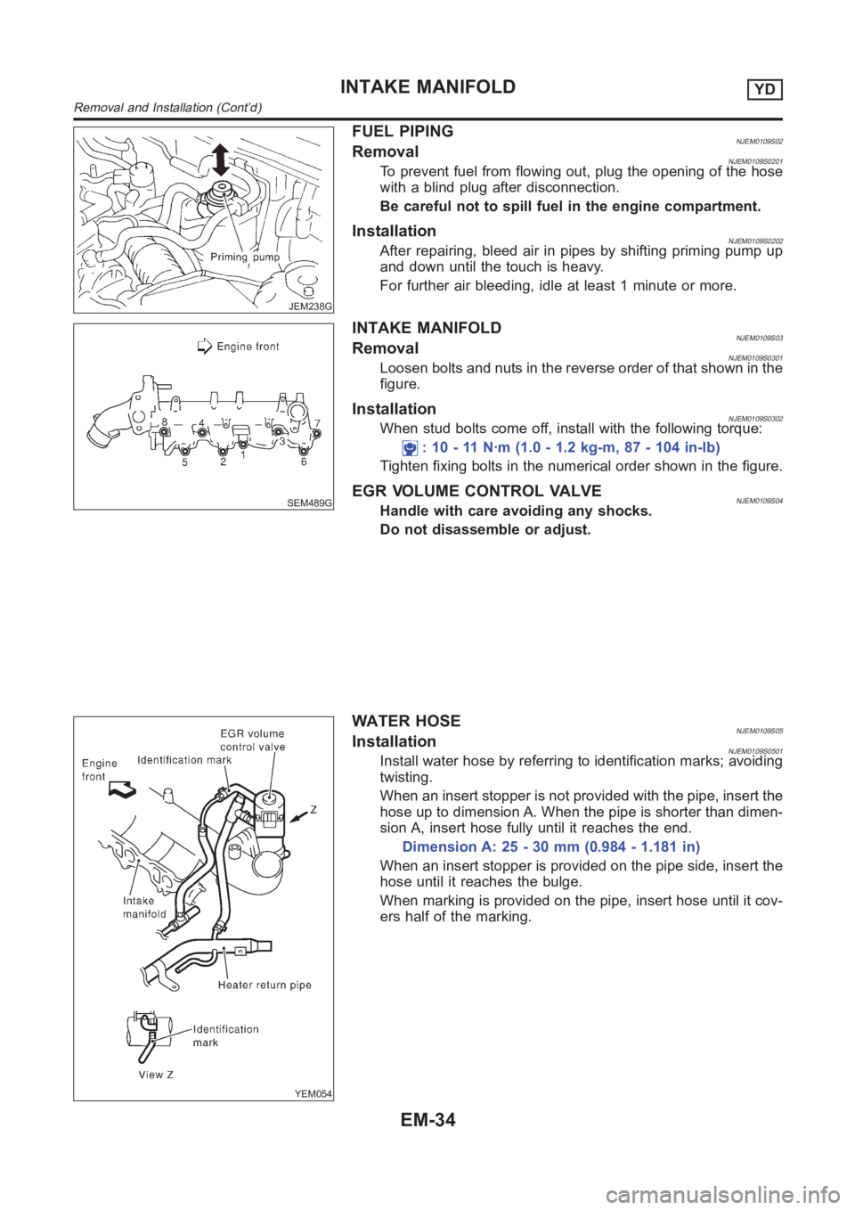
FUEL PIPINGNJEM0109S02RemovalNJEM0109S0201To prevent fuel from flowing out, plug the opening of the hose
with a blind plug after disconnection.
Be careful not to spill fuel in the engine compartment.
InstallationNJEM0109S0202After repairing, bleed air in pipes by shifting priming pump up
and down until the touch is heavy.
For further air bleeding, idle at least 1 minute or more.
SEM489G
INTAKE MANIFOLDNJEM0109S03RemovalNJEM0109S0301Loosen bolts and nuts in the reverse order of that shown in the
figure.
InstallationNJEM0109S0302When stud bolts come off, install with the following torque:
: 10 - 11 N·m (1.0 - 1.2 kg-m, 87 - 104 in-lb)
Tighten fixing bolts in the numerical order shown in the figure.
EGR VOLUME CONTROL VALVENJEM0109S04Handle with care avoiding any shocks.
Do not disassemble or adjust.
YEM054
WATER HOSENJEM0109S05InstallationNJEM0109S0501Install water hose by referring to identification marks; avoiding
twisting.
When an insert stopper is not provided with the pipe, insert the
hose up to dimension A. When the pipe is shorter than dimen-
sion A, insert hose fully until it reaches the end.
Dimension A: 25 - 30 mm (0.984 - 1.181 in)
When an insert stopper is provided on the pipe side, insert the
hose until it reaches the bulge.
When marking is provided on the pipe, insert hose until it cov-
ers half of the marking.
INTAKE MANIFOLDYD
Removal and Installation (Cont’d)
EM-34
Page 249 of 3189
SEM189G
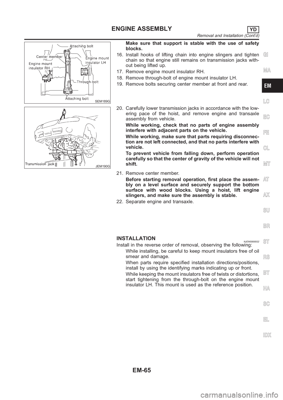
Make sure that support is stable with the use of safety
blocks.
16. Install hooks of lifting chain into engine slingers and tighten
chain so that engine still remains on transmission jacks with-
out being lifted up.
17. Remove engine mount insulator RH.
18. Remove through-bolt of engine mount insulator LH.
19. Remove bolts securing center member at front and rear.
JEM190G
20. Carefully lower transmission jacks in accordance with the low-
ering pace of the hoist, and remove engine and transaxle
assembly from vehicle.
While working, check that no parts of engine assembly
interfere with adjacent parts on the vehicle.
While working, make sure that parts requiring disconnec-
tion are not left connected, and that no parts interfere with
vehicle.
To prevent vehicle from falling down, perform operation
carefully so that the center of gravity of the vehicle will not
shift.
21. Remove center member.
Before starting removal operation, first place the assem-
bly on a level surface and securely support the bottom
surface with wood blocks. Using a hoist, lift engine
slingers, and make sure the assembly is stable.
22. Separate engine and transaxle.
INSTALLATIONNJEM0069S02Install in the reverse order of removal, observing the following:
While installing, be careful to keep mount insulators free of oil
smear and damage.
When parts require specified installation directions/positions,
install by using the identifying marks indicating up or front.
While keeping the mount insulators free of twists or distortions,
start tightening from the through-bolt on the engine mount
insulator LH. This mount is used as the reference position.
GI
MA
LC
EC
FE
CL
MT
AT
AX
SU
BR
ST
RS
BT
HA
SC
EL
IDX
ENGINE ASSEMBLYYD
Removal and Installation (Cont’d)
EM-65
Page 287 of 3189
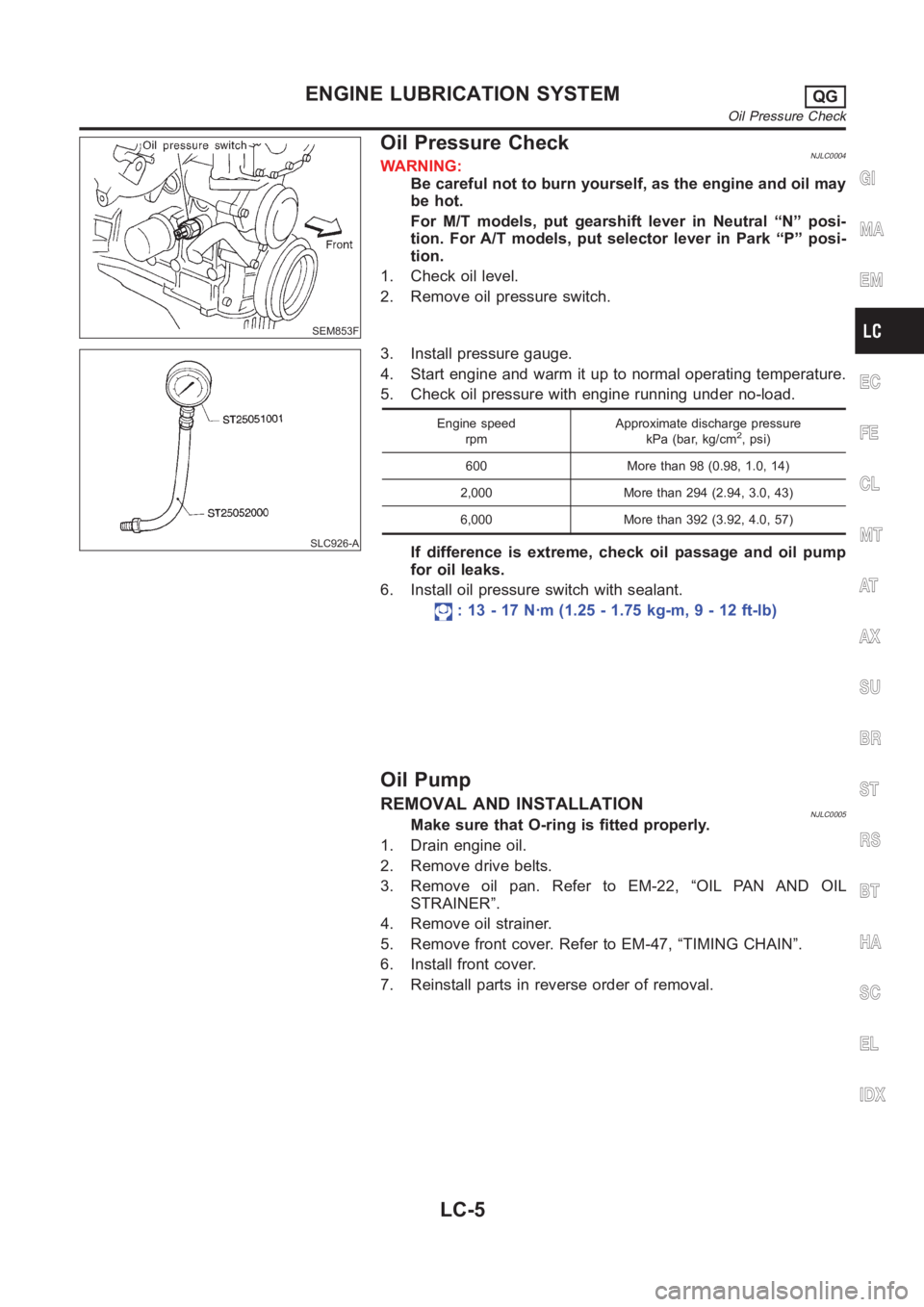
SEM853F
Oil Pressure CheckNJLC0004WARNING:
Be careful not to burn yourself, as the engine and oil may
be hot.
For M/T models, put gearshift lever in Neutral “N” posi-
tion. For A/T models, put selector lever in Park “P” posi-
tion.
1. Check oil level.
2. Remove oil pressure switch.
SLC926-A
3. Install pressure gauge.
4. Start engine and warm it up to normal operating temperature.
5. Check oil pressure with engine running under no-load.
Engine speed
rpmApproximate discharge pressure
kPa (bar, kg/cm2, psi)
600 More than 98 (0.98, 1.0, 14)
2,000 More than 294 (2.94, 3.0, 43)
6,000 More than 392 (3.92, 4.0, 57)
If difference is extreme, check oil passage and oil pump
for oil leaks.
6. Install oil pressure switch with sealant.
: 13 - 17 N·m (1.25 - 1.75 kg-m, 9 - 12 ft-lb)
Oil Pump
REMOVAL AND INSTALLATIONNJLC0005Make sure that O-ring is fitted properly.
1. Drain engine oil.
2. Remove drive belts.
3. Remove oil pan. Refer to EM-22, “OIL PAN AND OIL
STRAINER”.
4. Remove oil strainer.
5. Remove front cover. Refer to EM-47, “TIMING CHAIN”.
6. Install front cover.
7. Reinstall parts in reverse order of removal.
GI
MA
EM
EC
FE
CL
MT
AT
AX
SU
BR
ST
RS
BT
HA
SC
EL
IDX
ENGINE LUBRICATION SYSTEMQG
Oil Pressure Check
LC-5
Page 354 of 3189
![NISSAN ALMERA N16 2003 Electronic Repair Manual EC-24
[QG (WITH EURO-OBD)]
ENGINE CONTROL SYSTEM
ECM memory. The program value is preset by engine operating conditions. These conditions are determined
by input signals (for engine speed and i NISSAN ALMERA N16 2003 Electronic Repair Manual EC-24
[QG (WITH EURO-OBD)]
ENGINE CONTROL SYSTEM
ECM memory. The program value is preset by engine operating conditions. These conditions are determined
by input signals (for engine speed and i](/manual-img/5/57350/w960_57350-353.png)
EC-24
[QG (WITH EURO-OBD)]
ENGINE CONTROL SYSTEM
ECM memory. The program value is preset by engine operating conditions. These conditions are determined
by input signals (for engine speed and intake air) from the crankshaft position sensor (POS), the camshaft
position sensor (PHASE) and the mass air flow sensor.
VARIOUS FUEL INJECTION INCREASE/DECREASE COMPENSATION
In addition, the amount of fuel injected is compensated to improve engine performance under various operat-
ing conditions as listed below.
●During warm-up
●When starting the engine
●During acceleration
●Hot-engine operation
●When selector lever is changed from “N” to “D” (A/T models)
●High-load, high-speed operation
●During deceleration
●During high engine speed operation
MIXTURE RATIO FEEDBACK CONTROL (CLOSED LOOP CONTROL)
The mixture ratio feedback system provides the best air-fuel mixture ratio for driveability and emission control.
The three way catalyst (manifold) can then better reduce CO, HC and NOx emissions. This system uses
heated oxygen sensor 1 in the exhaust manifold to monitor if the engine operation is rich or lean. The ECM
adjusts the injection pulse width according to the sensor voltage signal. For more information about heated
oxygen sensor 1, refer to EC-155
. This maintains the mixture ratio within the range of stoichiometric (ideal air-
fuel mixture).
This stage is referred to as the closed loop control condition.
Heated oxygen sensor 2 is located downstream of the three way catalyst (manifold). Even if the switching
characteristics of heated oxygen sensor 1 shift, the air-fuel ratio is controlled to stoichiometric by the signal
from heated oxygen sensor 2.
Open Loop Control
The open loop system condition refers to when the ECM detects any of the following conditions. Feedback
control stops in order to maintain stabilized fuel combustion.
●Deceleration and acceleration
●High-load, high-speed operation
●Malfunction of heated oxygen sensor 1 or its circuit
●Insufficient activation of heated oxygen sensor 1 at low engine coolant temperature
●High engine coolant temperature
●During warm-up
●After shifting from “N” to “D” (A/T models)
●When starting the engine
MIXTURE RATIO SELF-LEARNING CONTROL
The mixture ratio feedback control system monitors the mixture ratio signal transmitted from heated oxygen
sensor 1. This feedback signal is then sent to the ECM. The ECM controls the basic mixture ratio as close to
the theoretical mixture ratio as possible. However, the basic mixture ratio is not necessarily controlled as orig-
PBIB0121E
Page 411 of 3189
![NISSAN ALMERA N16 2003 Electronic Repair Manual TROUBLE DIAGNOSIS
EC-81
[QG (WITH EURO-OBD)]
C
D
E
F
G
H
I
J
K
L
MA
EC
2R/BHeated oxygen sensor 2
heater[Engine is running]
●Warm-up condition
●Engine speed: Below 3,800 rpm after the
following NISSAN ALMERA N16 2003 Electronic Repair Manual TROUBLE DIAGNOSIS
EC-81
[QG (WITH EURO-OBD)]
C
D
E
F
G
H
I
J
K
L
MA
EC
2R/BHeated oxygen sensor 2
heater[Engine is running]
●Warm-up condition
●Engine speed: Below 3,800 rpm after the
following](/manual-img/5/57350/w960_57350-410.png)
TROUBLE DIAGNOSIS
EC-81
[QG (WITH EURO-OBD)]
C
D
E
F
G
H
I
J
K
L
MA
EC
2R/BHeated oxygen sensor 2
heater[Engine is running]
●Warm-up condition
●Engine speed: Below 3,800 rpm after the
following conditions are met.
●Keeping the engine speed between 3,500
and 4,000 rpm for one minute and at idle
for one minute under no load.0 - 1.0V
[Ignition switch “ON”]
●Engine stopped.
[Engine is running]
●Engine speed is above 3,800 rpm.BATTERY VOLTAGE
(11 - 14V)
3RThrottle control motor power
supply[Ignition switch “ON”]BATTERY VOLTAGE
(11 - 14V)
4W
(LHD)
BR
(RHD)Throttle control motor
(Close)[Ignition switch “ON”]
●Engine stopped.
●Shift lever position is ″D″ (A/T models).
●Shift lever position is “1st” (M/T models).
●Accelerator pedal is releasing.0 - 14V
5B (LHD)
Y (RHD)Throttle control motor
(Open)[Ignition switch “ON”]
●Engine stopped.
●Shift lever position is ″D″ (A/T models).
●Shift lever position is “1st” (M/T models).
●Accelerator pedal is depressing.0 - 14V
12 LPower steering pressure
sensor[Engine is running]
●Steering wheel is being turned.0.5 - 4.0V
[Engine is running]
●Steering wheel is not being turned.0.4 - 0.8V
13 RCrankshaft position sensor
(POS)[Engine is running]
●Warm-up condition
●Idle speedApproximately 3.0V
[Engine is running]
●Engine speed is 2,000 rpm.Approximately 3.0V TERMI-
NAL
NO.WIRE
COLORITEM CONDITION DATA (DC Voltage)
PBIB0534E
PBIB0533E
PBIB0527E
PBIB0528E
Page 414 of 3189
![NISSAN ALMERA N16 2003 Electronic Repair Manual EC-84
[QG (WITH EURO-OBD)]
TROUBLE DIAGNOSIS
49 W Throttle position sensor 1[Ignition switch “ON”]
●Engine stopped.
●Shift lever position is ″D″ (A/T models).
●Shift lever position is � NISSAN ALMERA N16 2003 Electronic Repair Manual EC-84
[QG (WITH EURO-OBD)]
TROUBLE DIAGNOSIS
49 W Throttle position sensor 1[Ignition switch “ON”]
●Engine stopped.
●Shift lever position is ″D″ (A/T models).
●Shift lever position is �](/manual-img/5/57350/w960_57350-413.png)
EC-84
[QG (WITH EURO-OBD)]
TROUBLE DIAGNOSIS
49 W Throttle position sensor 1[Ignition switch “ON”]
●Engine stopped.
●Shift lever position is ″D″ (A/T models).
●Shift lever position is “1st” (M/T models).
●Accelerator pedal fully released.More than 0.36V
[Ignition switch “ON”]
●Engine stopped.
●Shift lever position is ″D″ (A/T models).
●Shift lever position is “1st” (M/T models).
●Accelerator pedal fully depressed.Less than 4.75V
50 Y Mass air flow sensor[Engine is running]
●Warm-up condition
●Idle speed1.0 - 1.7V
[Engine is running]
●Warm-up condition
●Engine speed is 2,500 rpm.1.5 - 2.1V
54 -Sensor ground
(Knock sensor shield circuit)[Engine is running]
●Idle speedApproximately 0V
57 BSensor ground
(Power steering pressure
sensor/Refrigerant pressure
sensor)[Engine is running]
●Warm-up condition
●Idle speedApproximately 0V
60
61
79
80L/R
BR
GY/R
PUIgnition signal No. 3
Ignition signal No. 1
Ignition signal No. 4
Ignition signal No. 2[Engine is running]
●Warm-up condition
●Idle speed0 - 0.1V
[Engine is running]
●Warm-up condition
●Engine speed is 2,000 rpm.0 - 0.2V TERMI-
NAL
NO.WIRE
COLORITEM CONDITION DATA (DC Voltage)
PBIB0521E
PBIB0522E