2003 NISSAN ALMERA N16 satellite navigation display
[x] Cancel search: satellite navigation displayPage 2339 of 3189

Trouble Diagnoses/YD Engine Models with
Common Rail and K9K Engine Models...................292
POWER DOOR LOCK - SUPER LOCK -...................301
System Description ..................................................301
Schematic <0011001100110011001100110011001100110011001100110011001100110011001100110011001100110011001100110011001100110011001100110011001100110011001100110011001100110011001100110011001100110011001100110011001100
11001100110011[..........304
Wiring Diagram - S/LOCK - .....................................306
Trouble Diagnosis/QG and YD Engine Models
with Common Rail ...................................................313
Trouble Diagnoses/YD Engine Models without
Common Rail and K9K Engine Models...................339
MULTI-REMOTE CONTROL SYSTEM.......................352
System Description ..................................................352
Wiring Diagram - MULTI - .......................................353
Trouble Diagnoses/QG and YD Engine Models
with Common Rail ...................................................355
Trouble Diagnoses/YD Engine Models without
Common Rail and K9K Engine Models...................360
ID Code Entry Procedure ........................................364
Remote Controller Battery Replacement.................365
THEFT WARNING SYSTEM.......................................366
Wiring Diagram - PRWIRE -....................................366
SMART ENTRANCE CONTROL SYSTEM.................368
Description <0011001100110011001100110011001100110011001100110011001100110011001100110011001100110011001100110011001100110011001100110011001100110011001100110011001100110011001100110011001100110011001100110011001100
110011[...........368
CONSULT-II <0011001100110011001100110011001100110011001100110011001100110011001100110011001100110011001100110011001100110011001100110011001100110011001100110011001100110011001100110011001100110011001100110011001100
1100110011[........369
Schematic <0011001100110011001100110011001100110011001100110011001100110011001100110011001100110011001100110011001100110011001100110011001100110011001100110011001100110011001100110011001100110011001100110011001100
11001100110011[..........374
Smart Entrance Control Unit Inspection Table ........376
Trouble Diagnoses...................................................378
Power Supply and Ground Circuit Check ...............379
CAN Communication Line Check ............................380
TIME CONTROL UNIT................................................381
Description <0011001100110011001100110011001100110011001100110011001100110011001100110011001100110011001100110011001100110011001100110011001100110011001100110011001100110011001100110011001100110011001100110011001100
110011[...........381
Trouble Diagnoses...................................................382
Schematic <0011001100110011001100110011001100110011001100110011001100110011001100110011001100110011001100110011001100110011001100110011001100110011001100110011001100110011001100110011001100110011001100110011001100
11001100110011[..........384
NATS (NISSAN ANTI-THEFT SYSTEM).....................386
Component Parts and Harness Connetor
Location <0011001100110011001100110011001100110011001100110011001100110011001100110011001100110011001100110011001100110011001100110011001100110011001100110011001100110011001100110011001100110011001100110011001100
110011001100110011[............386
System Description ..................................................386
System Composition ................................................387
Wiring Diagram - NATS -.........................................388
CONSULT-II <0011001100110011001100110011001100110011001100110011001100110011001100110011001100110011001100110011001100110011001100110011001100110011001100110011001100110011001100110011001100110011001100110011001100
1100110011[........390
Trouble Diagnoses/QG and YD Engine Models
with Common Rail ...................................................393
How to Replace NATS Antenna Amp ...................... 411
Trouble Diagnoses/YD Engine Models without
Common Rail and K9K Engine Models...................412
How to Replace NATS IMMU ..................................429
NAVIGATION SYSTEM...............................................430
System Description ..................................................430
Precautions for AV and NAVI Control Unit
Replacement <0011001100110011001100110011001100110011001100110011001100110011001100110011001100110011001100110011001100110011001100110011001100110011001100110011001100110011001100110011001100110011001100110011001100
110011[........440
Component Parts Location ......................................441
Location of Antenna .................................................441Schematic <0011001100110011001100110011001100110011001100110011001100110011001100110011001100110011001100110011001100110011001100110011001100110011001100110011001100110011001100110011001100110011001100110011001100
11001100110011[..........442
Wiring Diagram - NAVI - ..........................................443
Wiring Diagram - COMM -.......................................448
Terminals and Reference Value for AV and NAVI
Control Unit <0011001100110011001100110011001100110011001100110011001100110011001100110011001100110011001100110011001100110011001100110011001100110011001100110011001100110011001100110011001100110011001100110011001100
110011[..........450
Terminals and Reference Value for Display Unit ....454
Terminals and Reference Value for Multifunction
Switch <0011001100110011001100110011001100110011001100110011001100110011001100110011001100110011001100110011001100110011001100110011001100110011001100110011001100110011001100110011001100110011001100110011001100
11001100110011001100110011[.............456
Self-Diagnosis Function ...........................................457
Self-Diagnosis Mode................................................458
Confirmation/Adjustment Mode ...............................461
Power Supply and Ground Circuit Check ...............467
Check Display Unit, Multifunction Switch Power,
and Ground Circuit ..................................................469
Vehicle Speed Signal Check ...................................471
Illumination Control Signal Check ...........................472
Ignition Signal Check ...............................................473
Reverse Signal Check .............................................474
RGB Screen Is Not Shown......................................475
No Screens Appear .................................................477
Color of RGB Image Is Not Proper .........................477
RGB Screen Is Rolling ............................................482
Guide Sound Is Not Heard ......................................484
Multifunction Switch Controls Are Ineffective
(Rear Defogger Control Excluded) ..........................485
Air Conditioning Controls (Only) Are Ineffective
(Rear Defogger Control Excluded) ..........................489
Rear Defogger Does Not Operate...........................491
Rear Defogger Indicator Lamp Does Not
Illuminate<0011001100110011001100110011001100110011001100110011001100110011001100110011001100110011001100110011001100110011001100110011001100110011001100110011001100110011001100110011001100110011001100110011001100
1100110011[.............492
No Fuel Information Is Displayed/No Warning
Message Is Displayed .............................................493
Previous Conditions Are Not Stored........................495
The Position of The Current-Location Mark Is
Not Correct <0011001100110011001100110011001100110011001100110011001100110011001100110011001100110011001100110011001100110011001100110011001100110011001100110011001100110011001100110011001100110011001100110011001100
1100110011[.........495
Radio Wave From The GPS Satellite Is Not
Received <0011001100110011001100110011001100110011001100110011001100110011001100110011001100110011001100110011001100110011001100110011001100110011001100110011001100110011001100110011001100110011001100110011001100
110011001100110011[...........495
Display Does Not Change When Screen
Adjustment Is Performed .........................................496
Day/Night Display Switching Is Not Done. Night
Illumination for AV and NAVI Control Unit Does
Not Illuminate ...........................................................496
On Multifunction Switch, a Specific Switch Does
Not Operate in All Conditions ..................................496
Driving Information Is Inaccurate. Maintenance
Information Is Inaccurate .........................................496
System Does Not Start ............................................497
The Current Position Mark Is in the Wrong Place ..497
The Current-Location Mark Will Not Move
Forward/Backward ...................................................498
The Position of the Current-Location Mark Is Not
Correct <0011001100110011001100110011001100110011001100110011001100110011001100110011001100110011001100110011001100110011001100110011001100110011001100110011001100110011001100110011001100110011001100110011001100
1100110011001100110011[.............498
GI
MA
EM
LC
EC
FE
CL
MT
AT
AX
SU
BR
ST
RS
BT
HA
SC
IDX
CONTENTS(Cont’d)
EL-3
Page 2768 of 3189
data calculated previously by using radio waves from four or more
GPS satellites (two-dimensional positioning).
Accuracy of the GPS will deteriorate under the following conditions.
In two-dimensional positioning, the GPS accuracy will deterio-
rate when the altitude of the vehicle position changes.
There may be an error of approximately 10 m (30 ft.) in posi-
tion detected by three-dimensional positioning, which is more
accurate than two-dimensional positioning. The accuracy can
be even lower depending on the arrangement of the GPS sat-
ellites utilized for the positioning.
Position detection is not possible when the vehicle is in an area
where radio waves from the GPS satellite do not reach, such
as in a tunnel, parking lot in a building, and under an elevated
highway. Radio waves from the GPS satellites may not be
received when some object is located over the GPS antenna.
Position correction by GPS is not available while the vehicle is
stopped.
PKIA0248E
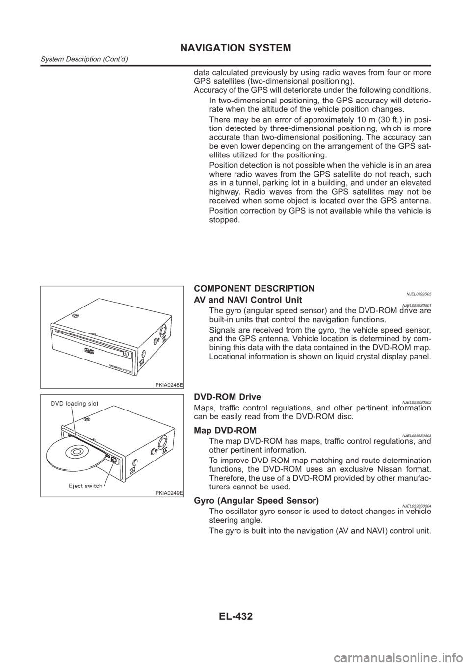
COMPONENT DESCRIPTIONNJEL0592S05AV and NAVI Control UnitNJEL0592S0501The gyro (angular speed sensor) and the DVD-ROM drive are
built-in units that control the navigation functions.
Signals are received from the gyro, the vehicle speed sensor,
and the GPS antenna. Vehicle location is determined by com-
bining this data with the data contained in the DVD-ROM map.
Locational information is shown on liquid crystal display panel.
PKIA0249E
DVD-ROM DriveNJEL0592S0502Maps, traffic control regulations, and other pertinent information
can be easily read from the DVD-ROM disc.
Map DVD-ROMNJEL0592S0503The map DVD-ROM has maps, traffic control regulations, and
other pertinent information.
To improve DVD-ROM map matching and route determination
functions, the DVD-ROM uses an exclusive Nissan format.
Therefore, the use of a DVD-ROM provided by other manufac-
turers cannot be used.
Gyro (Angular Speed Sensor)NJEL0592S0504The oscillator gyro sensor is used to detect changes in vehicle
steering angle.
The gyro is built into the navigation (AV and NAVI) control unit.
NAVIGATION SYSTEM
System Description (Cont’d)
EL-432
Page 2773 of 3189
Icon DescriptionReference
page
Edit Address Book Address Book can be edited. EL-438
Clear Memory Address Book, Previous destination or Avoid area can be deleted. EL-438
Auto Re-route ON/OFF ON/OFF of Auto Re-route can be switched. EL-438
Quick Stop Customer Setting One facility of your selection can be added to your Quick Stop. EL-438
Set Average speed for Estimated
Journey TimeAverage vehicle speed can be set to calibrate estimated journey time for the
destination.EL-439
GPS InformationThe GPS data includes longitude, latitude and altitude (distance above sea
level) of the present vehicle position, and current date and time for the area
in which the vehicle is being driven.
Also indicated are the GPS reception conditions and the GPS satellite posi-
tion.EL-439
Avoid Area Setting A particular area can be avoided when routing. —
Tracking on/off Tracking to the present vehicle position can be displayed.EL-439
Adjust Current LocationCurrent location of position marker can be adjusted. Direction of position
marker also can be calibrated when heading direction of the vehicle on the
display is not matched with the actual direction.EL-439
SKIA0554E
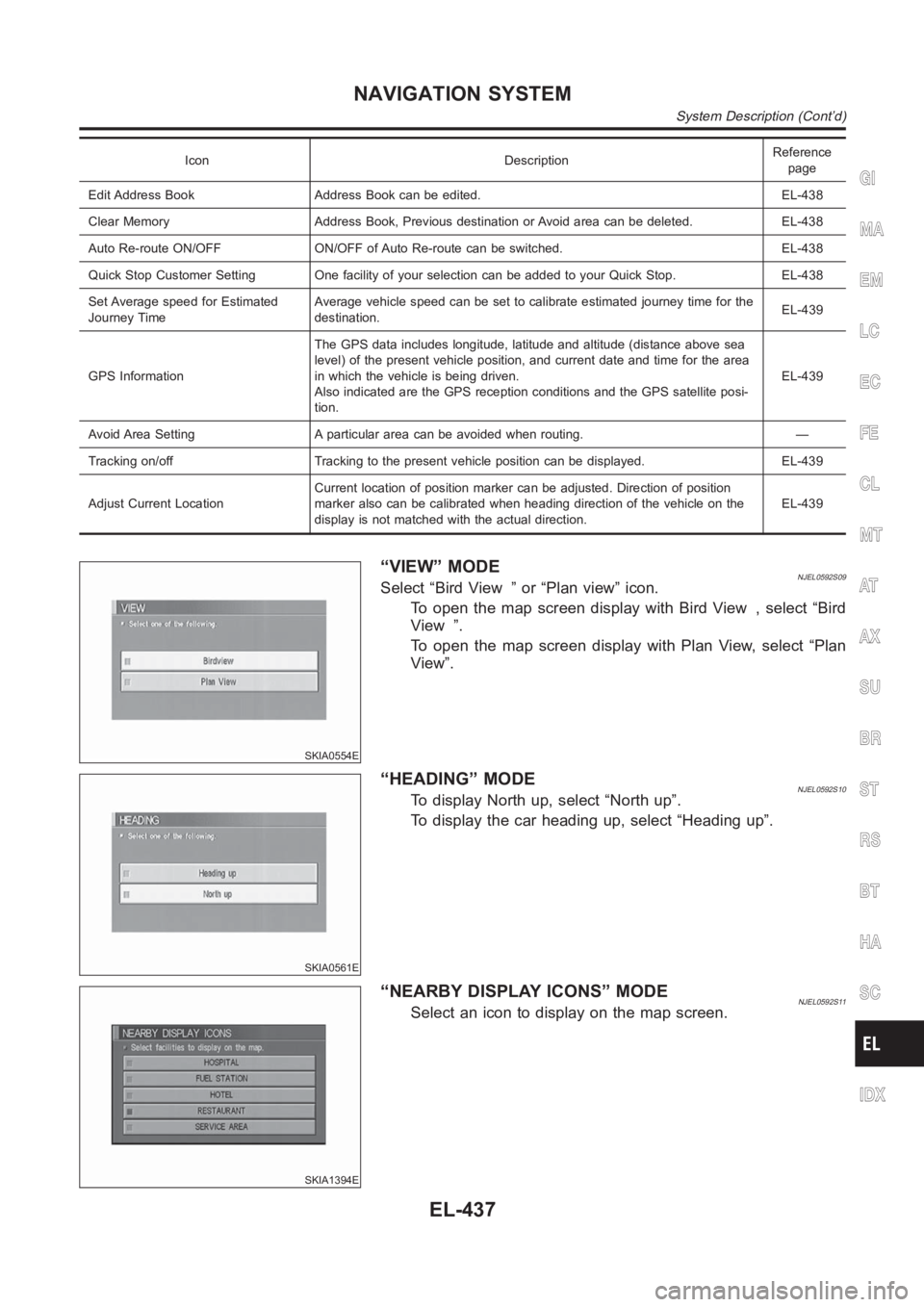
“VIEW” MODENJEL0592S09Select “Bird View ” or “Plan view” icon.
To open the map screen display with Bird View , select “Bird
View ”.
To open the map screen display with Plan View, select “Plan
View”.
SKIA0561E
“HEADING” MODENJEL0592S10To display North up, select “North up”.
To display the car heading up, select “Heading up”.
SKIA1394E
“NEARBY DISPLAY ICONS” MODENJEL0592S11Select an icon to display on the map screen.
GI
MA
EM
LC
EC
FE
CL
MT
AT
AX
SU
BR
ST
RS
BT
HA
SC
IDX
NAVIGATION SYSTEM
System Description (Cont’d)
EL-437
Page 2775 of 3189
SKIA1397E
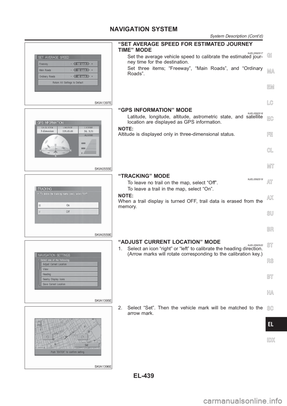
“SET AVERAGE SPEED FOR ESTIMATED JOURNEY
TIME” MODE
NJEL0592S17Set the average vehicle speed to calibrate the estimated jour-
ney time for the destination.
Set three items; “Freeway”, “Main Roads”, and “Ordinary
Roads”.
SKIA0555E
“GPS INFORMATION” MODENJEL0592S18Latitude, longitude, altitude, astrometric state, and satellite
location are displayed as GPS information.
NOTE:
Altitude is displayed only in three-dimensional status.
SKIA0559E
“TRACKING” MODENJEL0592S19To leave no trail on the map, select “Off”.
To leave a trail in the map, select “On”.
NOTE:
When a trail display is turned OFF, trail data is erased from the
memory.
SKIA1395E
“ADJUST CURRENT LOCATION” MODENJEL0592S201. Select an icon “right” or “left” to calibrate the heading direction.
(Arrow marks will rotate corresponding to the calibration key.)
SKIA1396E
2. Select “Set”. Then the vehicle mark will be matched to the
arrow mark.
GI
MA
EM
LC
EC
FE
CL
MT
AT
AX
SU
BR
ST
RS
BT
HA
SC
IDX
NAVIGATION SYSTEM
System Description (Cont’d)
EL-439
Page 2801 of 3189
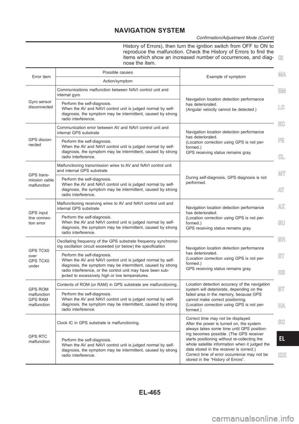
History of Errors), then turn the ignition switch from OFF to ON to
reproduce the malfunction. Check the History of Errors to find the
items which show an increased number of occurrences, and diag-
nose the item.
Error itemPossible causes
Example of symptom
Action/symptom
Gyro sensor
disconnectedCommunications malfunction between NAVI control unit and
internal gyro
Navigation location detection performance
has deteriorated.
(Angular velocity cannot be detected.) Perform the self-diagnosis.
When the AV and NAVI control unit is judged normal by self-
diagnosis, the symptom may be intermittent, caused by strong
radio interference.
GPS discon-
nectedCommunication error between AV and NAVI control unit and
internal GPS substrateNavigation location detection performance
has deteriorated.
(Location correction using GPS is not per-
formed.)
GPS receiving status remains gray. Perform the self-diagnosis.
When the AV and NAVI control unit is judged normal by self-
diagnosis, the symptom may be intermittent, caused by strong
radio interference.
GPS trans-
mission cable
malfunctionMalfunctioning transmission wires to AV and NAVI control unit
and internal GPS substrate
During self-diagnosis, GPS diagnosis is not
performed. Perform the self-diagnosis.
When the AV and NAVI control unit is judged normal by self-
diagnosis, the symptom may be intermittent, caused by strong
radio interference.
GPS input
line connec-
tion errorMalfunctioning receiving wires to AV and NAVI control unit and
internal GPS substrateNavigation location detection performance
has deteriorated.
(Location correction using GPS is not per-
formed.)
GPS receiving status remains gray. Perform the self-diagnosis.
When the AV and NAVI control unit is judged normal by self-
diagnosis, the symptom may be intermittent, caused by strong
radio interference.
GPS TCX0
over
GPS TCX0
underOscillating frequency of the GPS substrate frequency synchroniz-
ing oscillation circuit exceeded (or below) the specification
Navigation location detection performance
has deteriorated.
(Location correction using GPS is not per-
formed.)
GPS receiving status remains gray. Perform the self-diagnosis.
When the AV and NAVI control unit is judged normal by self-
diagnosis, the symptom may be intermittent, caused by strong
radio interference, or the control unit may have been sub-
jected to excessively high or low temperatures.
GPS ROM
malfunction
GPS RAM
malfunctionContents of ROM (or RAM) in GPS substrate are malfunctioning.Location detection accuracy of the navigation
system will deteriorate, depending on the
failed area in the memory, because GPS
cannot make correct positioning.
(Location correction using GPS is not per-
formed.) Perform the self-diagnosis.
When the AV and NAVI control unit is judged normal by self-
diagnosis, the symptom may be intermittent, caused by strong
radio interference.
GPS RTC
malfunctionClock IC in GPS substrate is malfunctioning.Correct time may not be displayed.
After the power is turned on, the system
always takes some time until GPS position-
ing becomes possible. (The GPS receiver
starts positioning without re-collecting the
whole satellite information when it judged the
data stored in the receiver is correct.)
Correct time of error occurrence may not be
stored in the “History of Errors”. Perform the self-diagnosis.
When the AV and NAVI control unit is judged normal by self-
diagnosis, the symptom may be intermittent, caused by strong
radio interference.
GI
MA
EM
LC
EC
FE
CL
MT
AT
AX
SU
BR
ST
RS
BT
HA
SC
IDX
NAVIGATION SYSTEM
Confirmation/Adjustment Mode (Cont’d)
EL-465
Page 2836 of 3189
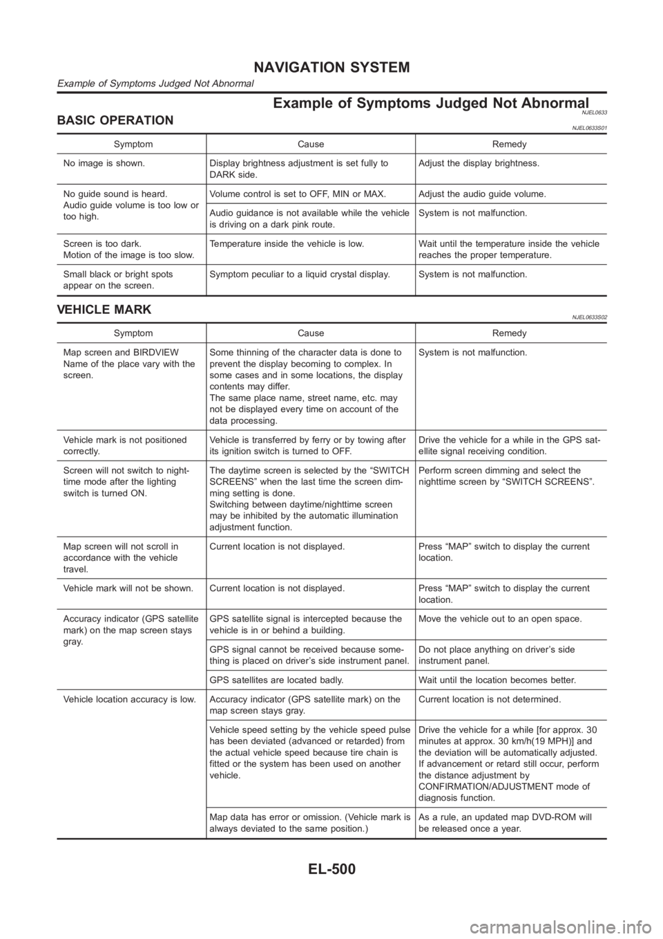
Example of Symptoms Judged Not AbnormalNJEL0633BASIC OPERATIONNJEL0633S01
Symptom Cause Remedy
No image is shown. Display brightness adjustment is set fully to
DARK side.Adjust the display brightness.
No guide sound is heard.
Audio guide volume is too low or
too high.Volume control is set to OFF, MIN or MAX. Adjust the audio guide volume.
Audio guidance is not available while the vehicle
is driving on a dark pink route.System is not malfunction.
Screen is too dark.
Motion of the image is too slow.Temperature inside the vehicle is low. Wait until the temperature inside the vehicle
reaches the proper temperature.
Small black or bright spots
appear on the screen.Symptom peculiar to a liquid crystal display. System is not malfunction.
VEHICLE MARKNJEL0633S02
Symptom Cause Remedy
Map screen and BIRDVIEW
Name of the place vary with the
screen.Some thinning of the character data is done to
prevent the display becoming to complex. In
some cases and in some locations, the display
contents may differ.
The same place name, street name, etc. may
not be displayed every time on account of the
data processing.System is not malfunction.
Vehicle mark is not positioned
correctly.Vehicle is transferred by ferry or by towing after
its ignition switch is turned to OFF.Drive the vehicle for a while in the GPS sat-
ellite signal receiving condition.
Screen will not switch to night-
time mode after the lighting
switch is turned ON.The daytime screen is selected by the “SWITCH
SCREENS” when the last time the screen dim-
ming setting is done.
Switching between daytime/nighttime screen
may be inhibited by the automatic illumination
adjustment function.Perform screen dimming and select the
nighttime screen by “SWITCH SCREENS”.
Map screen will not scroll in
accordance with the vehicle
travel.Current location is not displayed. Press “MAP” switch to display the current
location.
Vehicle mark will not be shown. Current location is not displayed. Press “MAP” switch to display the current
location.
Accuracy indicator (GPS satellite
mark) on the map screen stays
gray.GPS satellite signal is intercepted because the
vehicle is in or behind a building.Move the vehicle out to an open space.
GPS signal cannot be received because some-
thing is placed on driver’s side instrument panel.Do not place anything on driver’s side
instrument panel.
GPS satellites are located badly. Wait until the location becomes better.
Vehicle location accuracy is low. Accuracy indicator (GPS satellite mark)onthe
map screen stays gray.Current location is not determined.
Vehicle speed setting by the vehicle speed pulse
has been deviated (advanced or retarded) from
the actual vehicle speed because tire chain is
fitted or the system has been used on another
vehicle.Drive the vehicle for a while [for approx. 30
minutes at approx. 30 km/h(19 MPH)] and
the deviation will be automatically adjusted.
If advancement or retard still occur, perform
the distance adjustment by
CONFIRMATION/ADJUSTMENT mode of
diagnosis function.
Map data has error or omission. (Vehicle mark is
always deviated to the same position.)As a rule, an updated map DVD-ROM will
be released once a year.
NAVIGATION SYSTEM
Example of Symptoms Judged Not Abnormal
EL-500
Page 2842 of 3189
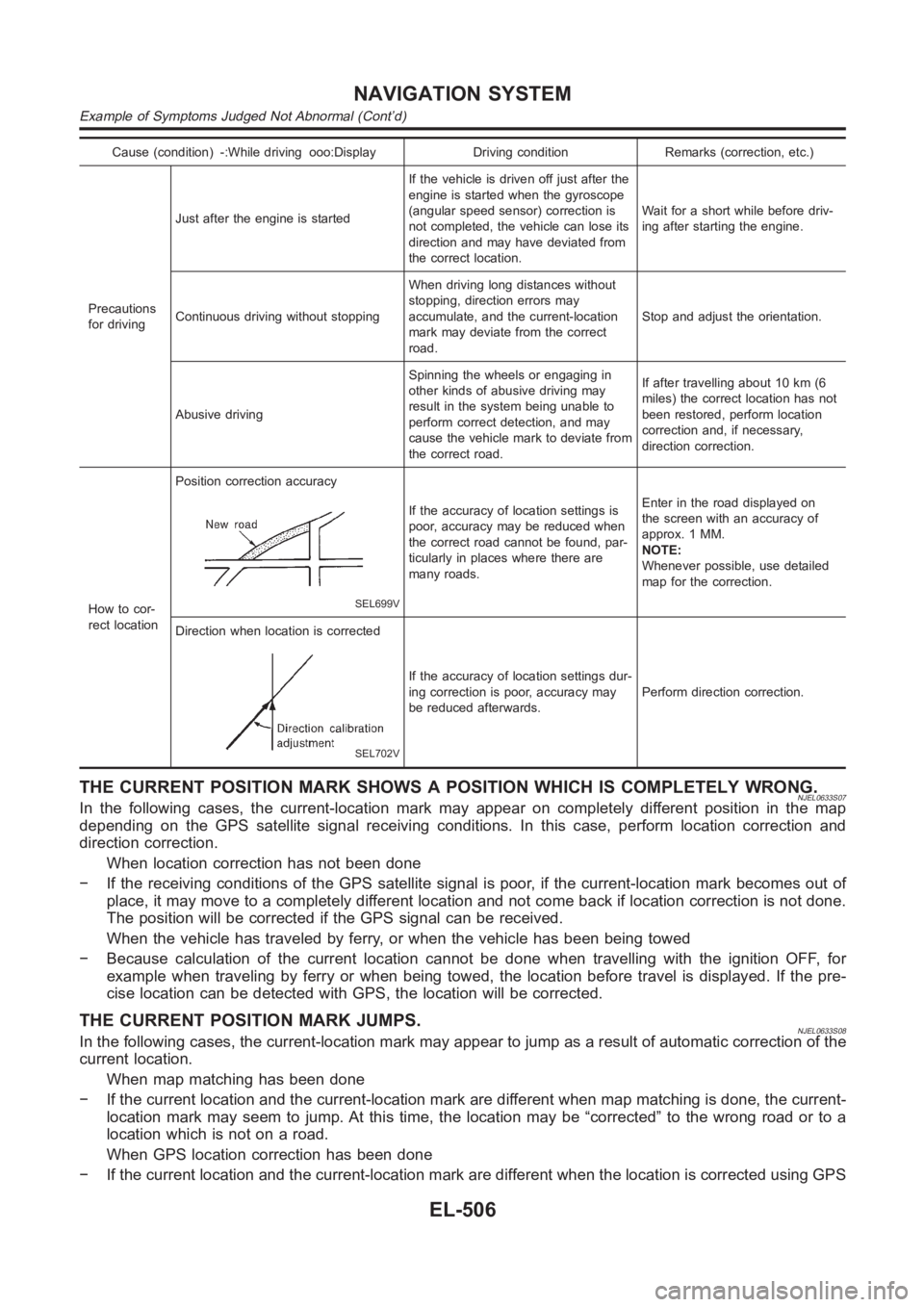
Cause (condition) -:While driving ooo:Display Driving condition Remarks (correction, etc.)
Precautions
for drivingJust after the engine is startedIf the vehicle is driven off just after the
engine is started when the gyroscope
(angular speed sensor) correction is
not completed, the vehicle can lose its
direction and may have deviated from
the correct location.Wait for a short while before driv-
ing after starting the engine.
Continuous driving without stoppingWhen driving long distances without
stopping, direction errors may
accumulate, and the current-location
mark may deviate from the correct
road.Stop and adjust the orientation.
Abusive drivingSpinning the wheels or engaging in
other kinds of abusive driving may
result in the system being unable to
perform correct detection, and may
cause the vehicle mark to deviate from
the correct road.If after travelling about 10 km (6
miles) the correct location has not
been restored, perform location
correction and, if necessary,
direction correction.
How to cor-
rect locationPosition correction accuracy
SEL699V
If the accuracy of location settings is
poor, accuracy may be reduced when
the correct road cannot be found, par-
ticularly in places where there are
many roads.Enter in the road displayed on
the screen with an accuracy of
approx. 1 MM.
NOTE:
Whenever possible, use detailed
map for the correction.
Direction when location is corrected
SEL702V
If the accuracy of location settings dur-
ing correction is poor, accuracy may
be reduced afterwards.Perform direction correction.
THE CURRENT POSITION MARK SHOWS A POSITION WHICH IS COMPLETELY WRONG.NJEL0633S07In the following cases, the current-location mark may appear on completely different position in the map
depending on the GPS satellite signal receiving conditions. In this case,perform location correction and
direction correction.
When location correction has not been done
− If the receiving conditions of the GPS satellite signal is poor, if the current-location mark becomes out of
place, it may move to a completely different location and not come back if location correction is not done.
The position will be corrected if the GPS signal can be received.
When the vehicle has traveled by ferry, or when the vehicle has been being towed
− Because calculation of the current location cannot be done when travelling with the ignition OFF, for
example when traveling by ferry or when being towed, the location before travel is displayed. If the pre-
cise location can be detected with GPS, the location will be corrected.
THE CURRENT POSITION MARK JUMPS.NJEL0633S08In the following cases, the current-location mark may appear to jump as a result of automatic correction of the
current location.
When map matching has been done
− If the current location and the current-location mark are different whenmap matching is done, the current-
location mark may seem to jump. At this time, the location may be “corrected” to the wrong road or to a
location which is not on a road.
When GPS location correction has been done
− If the current location and the current-location mark are different whenthe location is corrected using GPS
NAVIGATION SYSTEM
Example of Symptoms Judged Not Abnormal (Cont’d)
EL-506