2003 NISSAN ALMERA N16 Manual air conditioner
[x] Cancel search: Manual air conditionerPage 1 of 3189
Edition: August 2003
Release: October 2003 (01)
Publication No.: SM3E00-1N16E1E
Reference No.: 7711347018
GENERAL INFORMATIONGI
MAINTENANCEMA
ENGINE MECHANICAL – QGEM-QG
ENGINE MECHANICAL – YDEM-YD
ENGINE LUBRICATION &
COOLING SYSTEMSLC
ENGINE CONTROL SYSTEM – QGEC - QG
ENGINE CONTROL SYSTEM – YDEC - YD
ACCELERATOR CONTROL,
FUEL & EXHAUST SYSTEMSFE
CLUTCHCL
MANUAL TRANSAXLEMT
AUTOMATIC TRANSAXLEAT
FRONT & REAR AXLEAX
FRONT & REAR SUSPENSIONSU
BRAKE SYSTEMBR
STEERING SYSTEMST
RESTRAINT SYSTEMRS
BODY & TRIMBT
HEATER & MANUAL AIR CONDITIONERHA
AUTOMATIC AIR CONDITIONERATC
STARTING & CHARGING SYSTEMSSC
ELECTRICAL SYSTEMEL
ALPHABETICAL INDEXIDX
ALMERA
MODEL N16 SERIES
NISSAN EUROPE S.A.S.
© 2003 NISSAN EUROPE S.A.S.
Produced in The Netherlands
Not to be reproduced in whole or in part
without the prior written permission of
Nissan Europe S.A.S., Paris, France.
QUICK REFERENCE INDEX
Page 13 of 3189
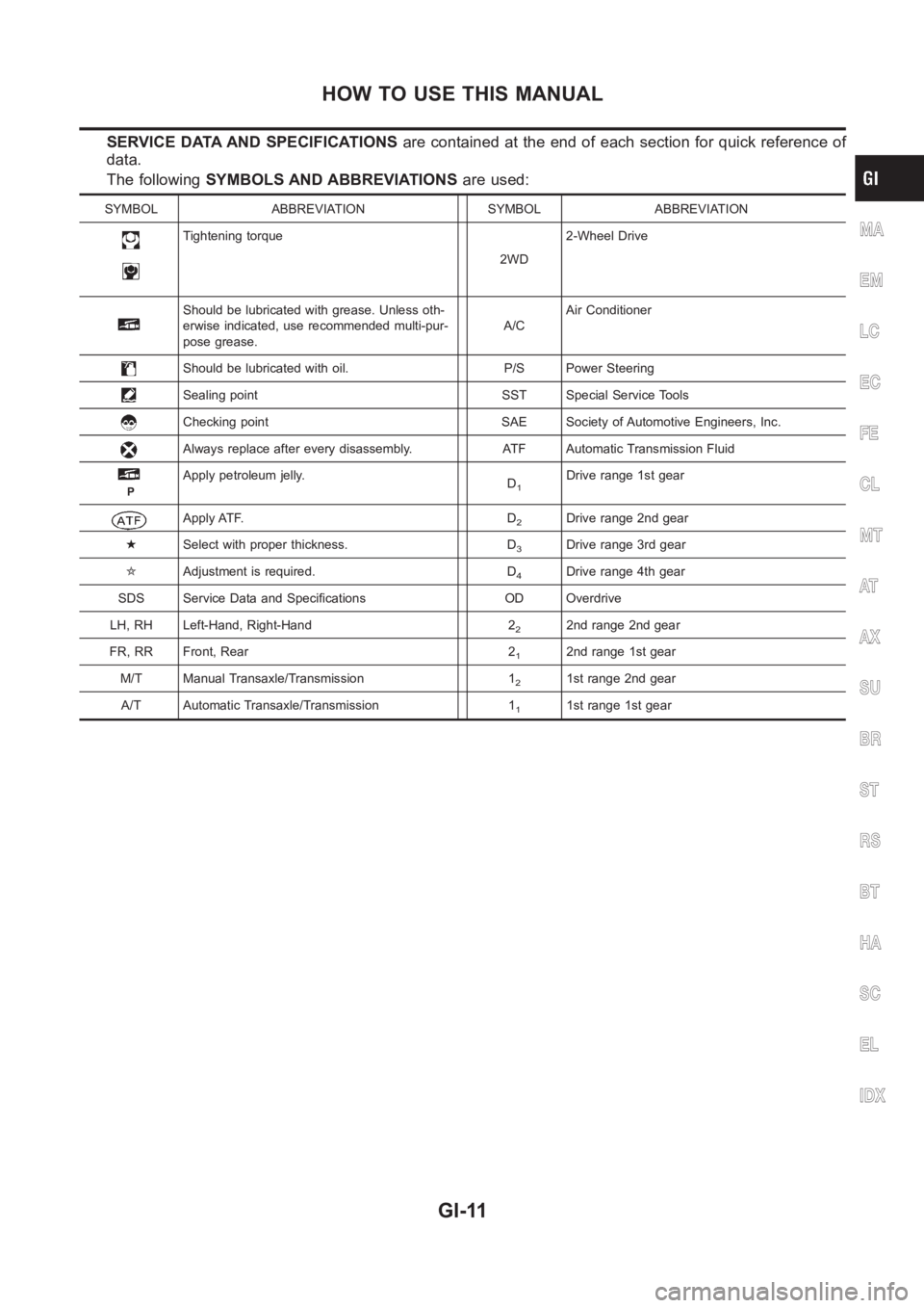
SERVICE DATA AND SPECIFICATIONSare contained at the end of each section for quick reference of
data.
The followingSYMBOLS AND ABBREVIATIONSare used:
SYMBOL ABBREVIATION SYMBOL ABBREVIATION
Tightening torque
2WD2-Wheel Drive
Should be lubricated with grease. Unless oth-
erwise indicated, use recommended multi-pur-
pose grease.A/CAir Conditioner
Should be lubricated with oil. P/S Power Steering
Sealing point SST Special Service Tools
Checking point SAE Society of Automotive Engineers, Inc.
Always replace after every disassembly. ATF Automatic Transmission Fluid
P
Apply petroleum jelly.
D1Drive range 1st gear
Apply ATF. D2Drive range 2nd gear
★Select with proper thickness. D
3Drive range 3rd gear
✩Adjustment is required. D
4Drive range 4th gear
SDS Service Data and Specifications OD Overdrive
LH, RH Left-Hand, Right-Hand 2
22nd range 2nd gear
FR, RR Front, Rear 2
12nd range 1st gear
M/T Manual Transaxle/Transmission 1
21st range 2nd gear
A/T Automatic Transaxle/Transmission 1
11st range 1st gear
MA
EM
LC
EC
FE
CL
MT
AT
AX
SU
BR
ST
RS
BT
HA
SC
EL
IDX
HOW TO USE THIS MANUAL
GI-11
Page 58 of 3189
NJMA0036
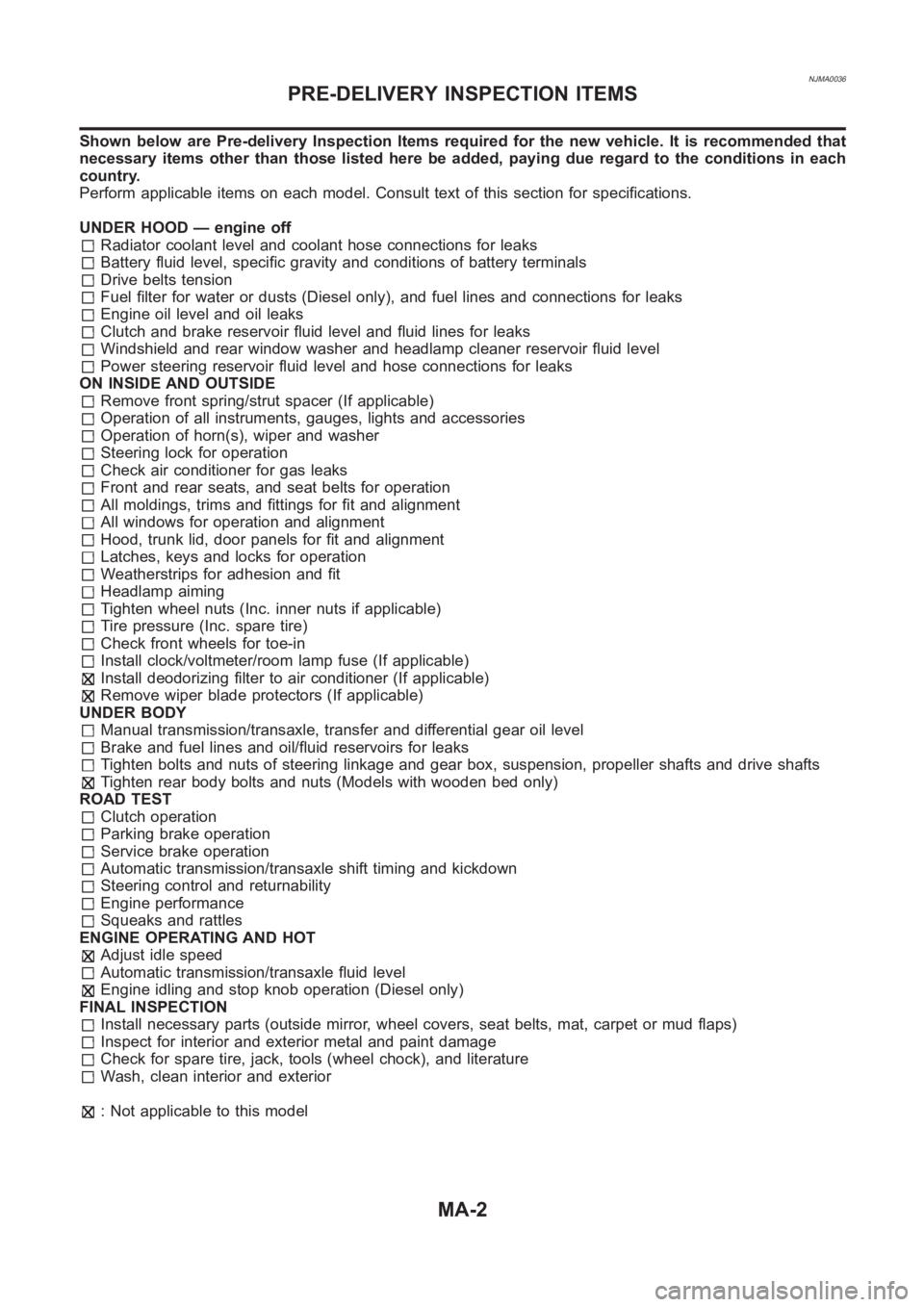
Shown below are Pre-delivery Inspection Items required for the new vehicle. It is recommended that
necessary items other than those listed here be added, paying due regard tothe conditions in each
country.
Perform applicable items on each model. Consult text of this section for specifications.
UNDER HOOD — engine off
Radiator coolant level and coolant hose connections for leaks
Battery fluid level, specific gravity and conditions of battery terminals
Drive belts tension
Fuel filter for water or dusts (Diesel only), and fuel lines and connections for leaks
Engine oil level and oil leaks
Clutch and brake reservoir fluid level and fluid lines for leaks
Windshield and rear window washer and headlamp cleaner reservoir fluid level
Power steering reservoir fluid level and hose connections for leaks
ON INSIDE AND OUTSIDE
Remove front spring/strut spacer (If applicable)
Operation of all instruments, gauges, lights and accessories
Operation of horn(s), wiper and washer
Steering lock for operation
Check air conditioner for gas leaks
Front and rear seats, and seat belts for operation
All moldings, trims and fittings for fit and alignment
All windows for operation and alignment
Hood, trunk lid, door panels for fit and alignment
Latches, keys and locks for operation
Weatherstrips for adhesion and fit
Headlamp aiming
Tighten wheel nuts (Inc. inner nuts if applicable)
Tire pressure (Inc. spare tire)
Check front wheels for toe-in
Install clock/voltmeter/room lamp fuse (If applicable)
Install deodorizing filter to air conditioner (If applicable)
Remove wiper blade protectors (If applicable)
UNDER BODY
Manual transmission/transaxle, transfer and differential gear oil level
Brake and fuel lines and oil/fluid reservoirs for leaks
Tighten bolts and nuts of steering linkage and gear box, suspension, propeller shafts and drive shafts
Tighten rear body bolts and nuts (Models with wooden bed only)
ROAD TEST
Clutch operation
Parking brake operation
Service brake operation
Automatic transmission/transaxle shift timing and kickdown
Steering control and returnability
Engine performance
Squeaks and rattles
ENGINE OPERATING AND HOT
Adjust idle speed
Automatic transmission/transaxle fluid level
Engine idling and stop knob operation (Diesel only)
FINAL INSPECTION
Install necessary parts (outside mirror, wheel covers, seat belts, mat, carpet or mud flaps)
Inspect for interior and exterior metal and paint damage
Check for spare tire, jack, tools (wheel chock), and literature
Wash, clean interior and exterior
: Not applicable to this model
PRE-DELIVERY INSPECTION ITEMS
MA-2
Page 429 of 3189
![NISSAN ALMERA N16 2003 Electronic Repair Manual TROUBLE DIAGNOSIS
EC-99
[QG (WITH EURO-OBD)]
C
D
E
F
G
H
I
J
K
L
MA
EC
5. Perform each diagnostic mode according to each service proce-
dure.
For further information, see the GST Operation Manu NISSAN ALMERA N16 2003 Electronic Repair Manual TROUBLE DIAGNOSIS
EC-99
[QG (WITH EURO-OBD)]
C
D
E
F
G
H
I
J
K
L
MA
EC
5. Perform each diagnostic mode according to each service proce-
dure.
For further information, see the GST Operation Manu](/manual-img/5/57350/w960_57350-428.png)
TROUBLE DIAGNOSIS
EC-99
[QG (WITH EURO-OBD)]
C
D
E
F
G
H
I
J
K
L
MA
EC
5. Perform each diagnostic mode according to each service proce-
dure.
For further information, see the GST Operation Manual of the
tool maker.
CONSULT-II Reference Value in Data Monitor ModeEBS00K3W
Remarks:
● Specification data are reference values.
● Specification data are output/input values which are detected or supplied by the ECM at the connector.
* Specification data may not be directly related to their components signals/values/operations.
i.e. Adjust ignition timing with a timing light before monitoring IGN TIMING, because the monitor may show the specification data in
spite of the ignition timing not being adjusted to the specification data. This IGN TIMING monitors the data calculated by the ECM
according to the signals input from the camshaft position sensor and other ignition timing related sensors.
SEF416S
MONITOR ITEM CONDITION SPECIFICATION
ENG SPEED
●Tachometer: Connect
●Run engine and compare tachometer indication with the CONSULT-II
value.Almost the same speed as the
CONSULT-II value.
MAS A/F SE-B1
●Engine: After warming up
●Air conditioner switch: OFF
●Shift lever:
N (A/T models)
Neutral (M/T models)
●No-loadIdle Approx. 1.0 - 1.7V
2,500 rpm Approx. 1.5 - 2.1V
B/FUEL SCHDL
●Engine: After warming up
●Shift lever:
N (A/T models)
Neutral (M/T models)
●Air conditioner switch: OFF
●No-loadIdle 1.5 - 3.0 msec
2,000 rpm 1.2 - 3.0 msec
A/F ALPHA-B1
●Engine: After warming upMaintaining engine speed at 2,000
rpm75% - 125%
COOLAN TEMP/S
●Engine: After warming up More than 70°C (158°F)
HO2S1 (B1)
●Engine: After warming upMaintaining engine speed at 2,000
rpm0 - 0.3V ←→ Approx. 0.6 - 1.0V
HO2S2 (B1)
●Engine: After warming up
●Keeping the engine speed
between 3,500 and 4,000 rpm
for one minute and at idle for
one minute under no loadRevving engine from idle to 3,000
rpm quickly.0 - 0.3V ←→ Approx. 0.6 - 1.0V
HO2S1 MNTR (B1)
●Engine: After warming upMaintaining engine speed at 2,000
rpmLEAN←→ RICH
Changes more than 5 times dur-
ing 10 seconds.
HO2S2 MNTR (B1)
●Engine: After warming up
●Keeping the engine speed
between 3,500 and 4,000 rpm
for one minute and at idle for
one minute under no loadRevving engine from idle to 3,000
rpm quickly.LEAN←→ RICH
VEH SPEED SE
●Turn drive wheels and compare speedometer indication with the CON-
SULT-II value.Almost the same speed as the
CONSULT-II value
BATTERY VOLT
●Ignition switch: ON (Engine stopped) 11 - 14V
Page 2005 of 3189
AIR CONDITIONER CONTROL
ATC-25
C
D
E
F
G
H
I
K
L
MA
B
AT C
Control OperationEJS001Z8
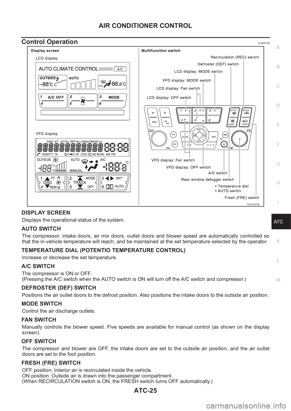
DISPLAY SCREEN
Displays the operational status of the system.
AUTO SWITCH
The compressor, intake doors, air mix doors, outlet doors and blower speed are automatically controlled so
that the in-vehicle temperature will reach, and be maintained at the set temperature selected by the operator.
TEMPERATURE DIAL (POTENTIO TEMPERATURE CONTROL)
Increase or decrease the set temperature.
A/C SWITCH
The compressor is ON or OFF.
(Pressing the A/C switch when the AUTO switch is ON will turn off the A/C switch and compressor.)
DEFROSTER (DEF) SWITCH
Positions the air outlet doors to the defrost position. Also positions the intake doors to the outside air position.
MODE SWITCH
Control the air discharge outlets.
FAN SWITCH
Manually controls the blower speed. Five speeds are available for manual control (as shown on the display
screen).
OFF SWITCH
The compressor and blower are OFF, the intake doors are set to the outside air position, and the air outlet
doors are set to the foot position.
FRESH (FRE) SWITCH
OFF position: Interior air is recirculated inside the vehicle.
ON position: Outside air is drawn into the passenger compartment.
(When RECIRCULATION switch is ON, the FRESH switch turns OFF automatically.)
RJIA1675E
Page 2935 of 3189
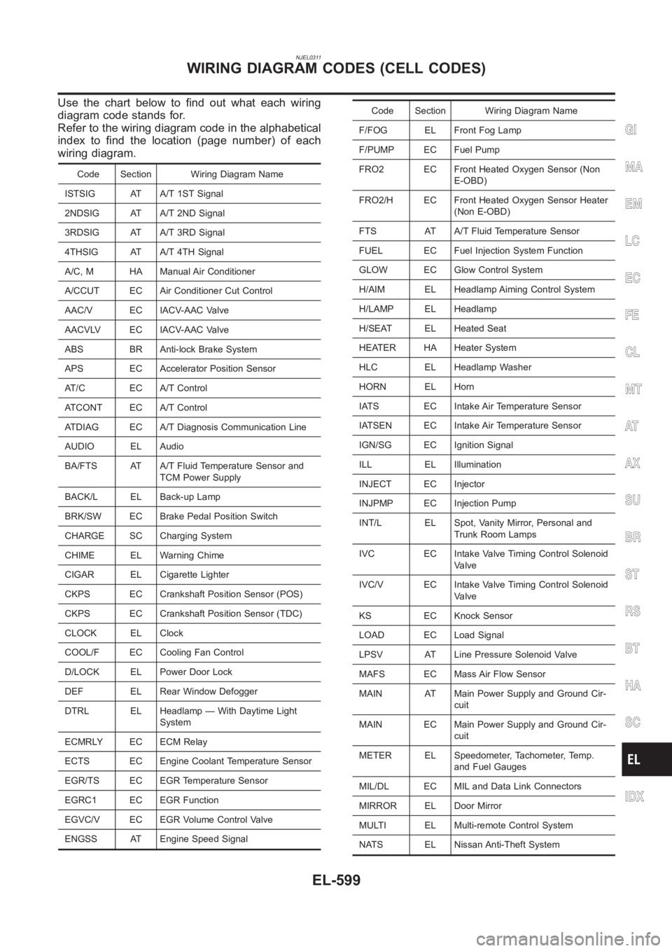
NJEL0311
Use the chart below to find out what each wiring
diagram code stands for.
Refer to the wiring diagram code in the alphabetical
index to find the location (page number) of each
wiring diagram.
Code Section Wiring Diagram Name
ISTSIG AT A/T 1ST Signal
2NDSIG AT A/T 2ND Signal
3RDSIG AT A/T 3RD Signal
4THSIG AT A/T 4TH Signal
A/C, M HA Manual Air Conditioner
A/CCUT EC Air Conditioner Cut Control
AAC/V EC IACV-AAC Valve
AACVLV EC IACV-AAC Valve
ABS BR Anti-lock Brake System
APS EC Accelerator Position Sensor
AT/C EC A/T Control
ATCONT EC A/T Control
ATDIAG EC A/T Diagnosis Communication Line
AUDIO EL Audio
BA/FTS AT A/T Fluid Temperature Sensor and
TCM Power Supply
BACK/L EL Back-up Lamp
BRK/SW EC Brake Pedal Position Switch
CHARGE SC Charging System
CHIME EL Warning Chime
CIGAR EL Cigarette Lighter
CKPS EC Crankshaft Position Sensor (POS)
CKPS EC Crankshaft Position Sensor (TDC)
CLOCK EL Clock
COOL/F EC Cooling Fan Control
D/LOCK EL Power Door Lock
DEF EL Rear Window Defogger
DTRL EL Headlamp — With Daytime Light
System
ECMRLY EC ECM Relay
ECTS EC Engine Coolant Temperature Sensor
EGR/TS EC EGR Temperature Sensor
EGRC1 EC EGR Function
EGVC/V EC EGR Volume Control Valve
ENGSS AT Engine Speed Signal
Code Section Wiring Diagram Name
F/FOG EL Front Fog Lamp
F/PUMP EC Fuel Pump
FRO2 EC Front Heated Oxygen Sensor (Non
E-OBD)
FRO2/H EC Front Heated Oxygen Sensor Heater
(Non E-OBD)
FTS AT A/T Fluid Temperature Sensor
FUEL EC Fuel Injection System Function
GLOW EC Glow Control System
H/AIM EL Headlamp Aiming Control System
H/LAMP EL Headlamp
H/SEAT EL Heated Seat
HEATER HA Heater System
HLC EL Headlamp Washer
HORN EL Horn
IATS EC Intake Air Temperature Sensor
IATSEN EC Intake Air Temperature Sensor
IGN/SG EC Ignition Signal
ILL EL Illumination
INJECT EC Injector
INJPMP EC Injection Pump
INT/L EL Spot, Vanity Mirror, Personal and
Trunk Room Lamps
IVC EC Intake Valve Timing Control Solenoid
Valve
IVC/V EC Intake Valve Timing Control Solenoid
Valve
KS EC Knock Sensor
LOAD EC Load Signal
LPSV AT Line Pressure Solenoid Valve
MAFS EC Mass Air Flow Sensor
MAIN AT Main Power Supply and Ground Cir-
cuit
MAIN EC Main Power Supply and Ground Cir-
cuit
METER EL Speedometer, Tachometer, Temp.
and Fuel Gauges
MIL/DL EC MIL and Data Link Connectors
MIRROR EL Door Mirror
MULTI EL Multi-remote Control System
NATS EL Nissan Anti-Theft System
GI
MA
EM
LC
EC
FE
CL
MT
AT
AX
SU
BR
ST
RS
BT
HA
SC
IDX
WIRING DIAGRAM CODES (CELL CODES)
EL-599
Page 2937 of 3189
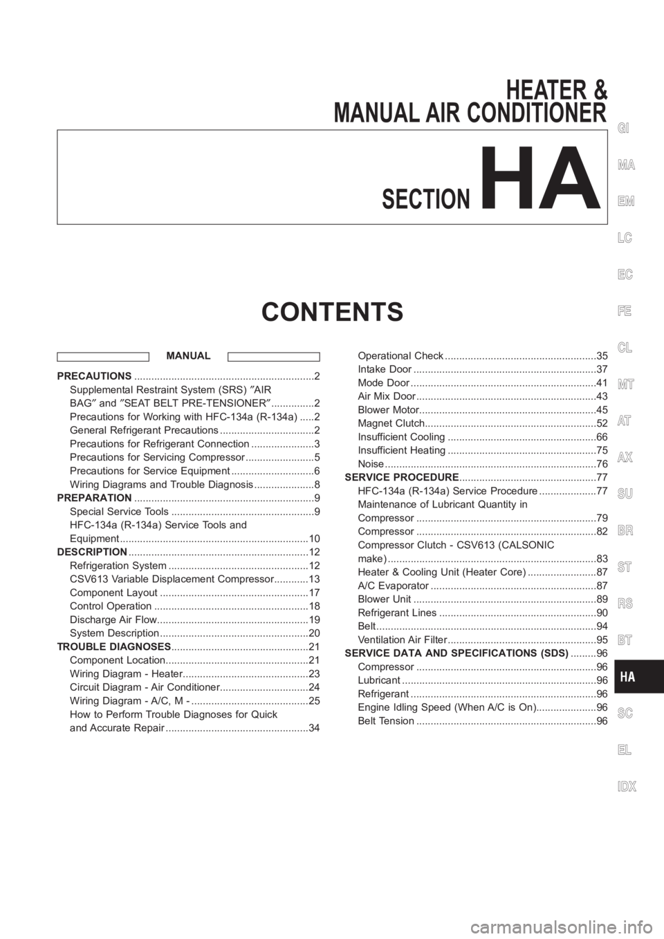
HEATER &
MANUAL AIR CONDITIONER
SECTION
HA
CONTENTS
MANUAL
PRECAUTIONS<0011001100110011001100110011001100110011001100110011001100110011001100110011001100110011001100110011001100110011001100110011001100110011001100110011001100110011001100110011001100110011001100110011001100
11001100110011001100110011001100110011001100110011[2
Supplemental Restraint System (SRS)″AIR
BAG″and″SEAT BELT PRE-TENSIONER″...............2
Precautions for Working with HFC-134a (R-134a) .....2
General Refrigerant Precautions .................................2
Precautions for Refrigerant Connection ......................3
Precautions for Servicing Compressor ........................5
Precautions for Service Equipment .............................6
Wiring Diagrams and Trouble Diagnosis .....................8
PREPARATION<0011001100110011001100110011001100110011001100110011001100110011001100110011001100110011001100110011001100110011001100110011001100110011001100110011001100110011001100110011001100110011001100110011001100
11001100110011001100110011001100110011001100110011[9
Special Service Tools ..................................................9
HFC-134a (R-134a) Service Tools and
Equipment <0011001100110011001100110011001100110011001100110011001100110011001100110011001100110011001100110011001100110011001100110011001100110011001100110011001100110011001100110011001100110011001100110011001100
11001100110011[............10
DESCRIPTION<0011001100110011001100110011001100110011001100110011001100110011001100110011001100110011001100110011001100110011001100110011001100110011001100110011001100110011001100110011001100110011001100110011001100
11001100110011001100110011001100110011001100110011[12
Refrigeration System .................................................12
CSV613 Variable Displacement Compressor............13
Component Layout ....................................................17
Control Operation ......................................................18
Discharge Air Flow.....................................................19
System Description ....................................................20
TROUBLE DIAGNOSES................................................21
Component Location..................................................21
Wiring Diagram - Heater............................................23
Circuit Diagram - Air Conditioner...............................24
Wiring Diagram - A/C, M - .........................................25
How to Perform Trouble Diagnoses for Quick
and Accurate Repair ..................................................34Operational Check .....................................................35
Intake Door <0011001100110011001100110011001100110011001100110011001100110011001100110011001100110011001100110011001100110011001100110011001100110011001100110011001100110011001100110011001100110011001100110011001100
1100110011[...........37
Mode Door <0011001100110011001100110011001100110011001100110011001100110011001100110011001100110011001100110011001100110011001100110011001100110011001100110011001100110011001100110011001100110011001100110011001100
110011001100110011[..........41
Air Mix Door <0011001100110011001100110011001100110011001100110011001100110011001100110011001100110011001100110011001100110011001100110011001100110011001100110011001100110011001100110011001100110011001100110011001100
1100110011[..........43
Blower Motor<0011001100110011001100110011001100110011001100110011001100110011001100110011001100110011001100110011001100110011001100110011001100110011001100110011001100110011001100110011001100110011001100110011001100
110011[..........45
Magnet Clutch<0011001100110011001100110011001100110011001100110011001100110011001100110011001100110011001100110011001100110011001100110011001100110011001100110011001100110011001100110011001100110011001100110011001100
11[.........52
Insufficient Cooling ....................................................66
Insufficient Heating ....................................................75
Noise <0011001100110011001100110011001100110011001100110011001100110011001100110011001100110011001100110011001100110011001100110011001100110011001100110011001100110011001100110011001100110011001100110011001100
110011001100110011001100110011[................76
SERVICE PROCEDURE................................................77
HFC-134a (R-134a) Service Procedure ....................77
Maintenance of Lubricant Quantity in
Compressor <0011001100110011001100110011001100110011001100110011001100110011001100110011001100110011001100110011001100110011001100110011001100110011001100110011001100110011001100110011001100110011001100110011001100
1100110011[..........79
Compressor <0011001100110011001100110011001100110011001100110011001100110011001100110011001100110011001100110011001100110011001100110011001100110011001100110011001100110011001100110011001100110011001100110011001100
1100110011[..........82
Compressor Clutch - CSV613 (CALSONIC
make) <0011001100110011001100110011001100110011001100110011001100110011001100110011001100110011001100110011001100110011001100110011001100110011001100110011001100110011001100110011001100110011001100110011001100
110011001100110011001100110011[...............83
Heater & Cooling Unit (Heater Core) ........................87
A/C Evaporator ..........................................................87
Blower Unit <0011001100110011001100110011001100110011001100110011001100110011001100110011001100110011001100110011001100110011001100110011001100110011001100110011001100110011001100110011001100110011001100110011001100
1100110011[...........89
Refrigerant Lines .......................................................90
Belt <0011001100110011001100110011001100110011001100110011001100110011001100110011001100110011001100110011001100110011001100110011001100110011001100110011001100110011001100110011001100110011001100110011001100
1100110011001100110011001100110011[..................94
Ventilation Air Filter ....................................................95
SERVICE DATA AND SPECIFICATIONS (SDS).........96
Compressor <0011001100110011001100110011001100110011001100110011001100110011001100110011001100110011001100110011001100110011001100110011001100110011001100110011001100110011001100110011001100110011001100110011001100
1100110011[..........96
Lubricant <0011001100110011001100110011001100110011001100110011001100110011001100110011001100110011001100110011001100110011001100110011001100110011001100110011001100110011001100110011001100110011001100110011001100
11001100110011[..............96
Refrigerant <0011001100110011001100110011001100110011001100110011001100110011001100110011001100110011001100110011001100110011001100110011001100110011001100110011001100110011001100110011001100110011001100110011001100
110011[.............96
Engine Idling Speed (When A/C is On).....................96
Belt Tension <0011001100110011001100110011001100110011001100110011001100110011001100110011001100110011001100110011001100110011001100110011001100110011001100110011001100110011001100110011001100110011001100110011001100
110011[...........96
GI
MA
EM
LC
EC
FE
CL
MT
AT
AX
SU
BR
ST
RS
BT
SC
EL
IDX
Page 2941 of 3189
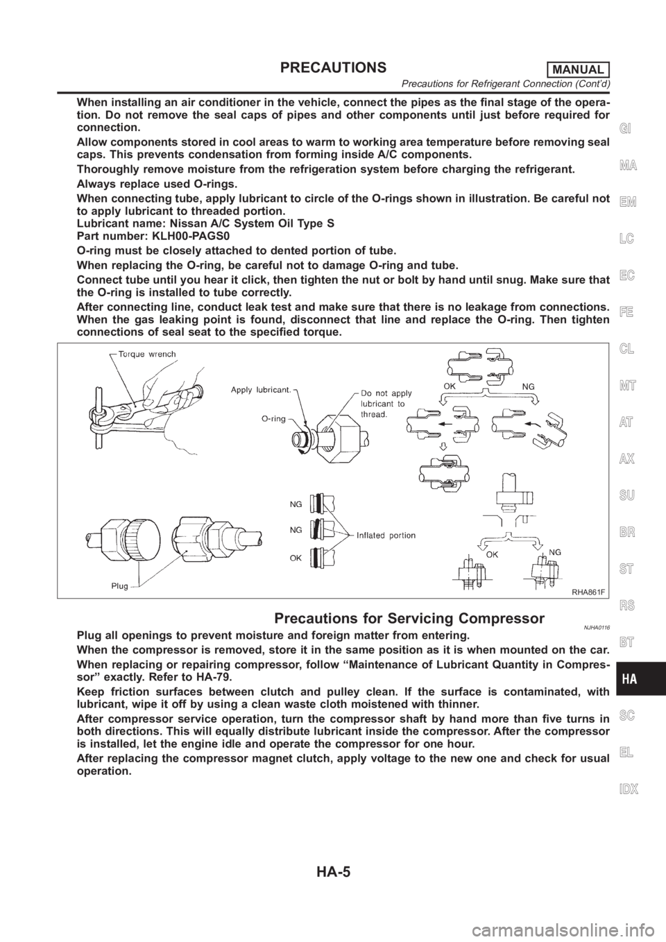
When installing an air conditioner in the vehicle, connect the pipes as thefinal stage of the opera-
tion. Do not remove the seal caps of pipes and other components until just before required for
connection.
Allow components stored in cool areas to warm to working area temperature before removing seal
caps. This prevents condensation from forming inside A/C components.
Thoroughly remove moisture from the refrigeration system before charging the refrigerant.
Always replace used O-rings.
When connecting tube, apply lubricant to circle of the O-rings shown in illustration. Be careful not
to apply lubricant to threaded portion.
Lubricant name: Nissan A/C System Oil Type S
Part number: KLH00-PAGS0
O-ring must be closely attached to dented portion of tube.
When replacing the O-ring, be careful not to damage O-ring and tube.
Connect tube until you hear it click, then tighten the nut or bolt by hand until snug. Make sure that
the O-ring is installed to tube correctly.
After connecting line, conduct leak test and make sure that there is no leakage from connections.
When the gas leaking point is found, disconnect that line and replace the O-ring. Then tighten
connections of seal seat to the specified torque.
RHA861F
Precautions for Servicing CompressorNJHA0116Plug all openings to prevent moisture and foreign matter from entering.
When the compressor is removed, store it in the same position as it is when mounted on the car.
When replacing or repairing compressor, follow “Maintenance of Lubricant Quantity in Compres-
sor” exactly. Refer to HA-79.
Keep friction surfaces between clutch and pulley clean. If the surface is contaminated, with
lubricant, wipe it off by using a clean waste cloth moistened with thinner.
After compressor service operation, turn the compressor shaft by hand more than five turns in
both directions. This will equally distribute lubricant inside the compressor. After the compressor
is installed, let the engine idle and operate the compressor for one hour.
After replacing the compressor magnet clutch, apply voltage to the new oneand check for usual
operation.
GI
MA
EM
LC
EC
FE
CL
MT
AT
AX
SU
BR
ST
RS
BT
SC
EL
IDX
PRECAUTIONSMANUAL
Precautions for Refrigerant Connection (Cont’d)
HA-5