Page 20 of 3189
SGI862-A
DETECTABLE LINES AND NON-DETECTABLE LINESNJGI0003S0205In some wiring diagrams, two kinds of lines, representing wires,
with different weight are used.
A line with regular weight (wider line) represents a “detectable
line for DTC (Diagnostic Trouble Code)”. A “detectable line for
DTC” is a circuit in which ECM can detect its malfunctions with
the on board diagnostic system.
A line with less weight (thinner line) represents a “non-detect-
able line for DTC”. A “non-detectable line for DTC” is a circuit
in which ECM cannot detect its malfunctions with the on board
diagnostic system.
HOW TO READ WIRING DIAGRAMS
Description (Cont’d)
GI-18
Page 26 of 3189

Engine Compartment
There are several reasons a vehicle or engine vibration could
cause an electrical complaint. Some of the things to check for are:
Connectors not fully seated.
Wiring harness not long enough and is being stressed due to
engine vibrations or rocking.
Wires laying across brackets or moving components.
Loose, dirty or corroded ground wires.
Wires routed too close to hot components.
To inspect components under the hood, start by verifying the integ-
rity of ground connections. (Refer to GROUND INSPECTION
described later.) First check that the system is properly grounded.
Then check for loose connection bygently shakingthe wiring or
components as previously explained. Using the wiring diagrams
inspect the wiring for continuity.
Behind The Instrument Panel
An improperly routed or improperly clamped harness can become
pinched during accessory installation. Vehicle vibration can aggra-
vate a harness which is routed along a bracket or near a screw.
Under Seating Areas
An unclamped or loose harness can cause wiring to be pinched by
seat components (such as slide guides) during vehicle vibration. If
the wiring runs under seating areas, inspect wire routing for pos-
sible damage or pinching.
SGI842
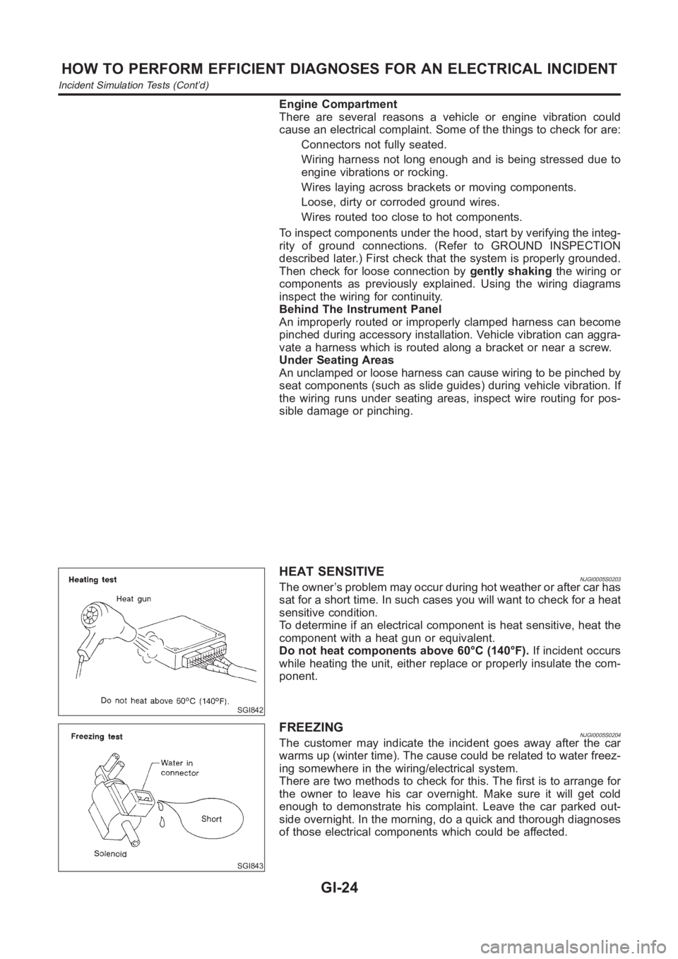
HEAT SENSITIVENJGI0005S0203The owner’s problem may occur during hot weather or after car has
sat for a short time. In such cases you will want to check for a heat
sensitive condition.
To determine if an electrical component is heat sensitive, heat the
component with a heat gun or equivalent.
Do not heat components above 60°C (140°F).If incident occurs
while heating the unit, either replace or properly insulate the com-
ponent.
SGI843
FREEZINGNJGI0005S0204The customer may indicate the incident goes away after the car
warms up (winter time). The cause could be related to water freez-
ing somewhere in the wiring/electrical system.
There are two methods to check for this. The first is to arrange for
the owner to leave his car overnight. Make sure it will get cold
enough to demonstrate his complaint. Leave the car parked out-
side overnight. In the morning, do a quick and thorough diagnoses
of those electrical components which could be affected.
HOW TO PERFORM EFFICIENT DIAGNOSES FOR AN ELECTRICAL INCIDENT
Incident Simulation Tests (Cont’d)
GI-24
Page 30 of 3189

no voltage; short is further down the circuit than the relay.
5) With SW1 closed, relay contacts jumped with fused jumper
wire check for voltage.
voltage; short is down the circuit of the relay or between the
relay and the disconnected solenoid (point C).
no voltage; retrace steps and check power to fuse block.
GROUND INSPECTIONNJGI0005S0304Ground connections are very important to the proper operation of
electrical and electronic circuits. Ground connections are often
exposed to moisture, dirt and other corrosive elements. The corro-
sion (rust) can become an unwanted resistance. This unwanted
resistance can change the way a circuit works.
Electronically controlled circuits are very sensitive to proper
grounding. A loose or corroded ground can drastically affect an
electronically controlled circuit. A poor or corroded ground can eas-
ily affect the circuit. Even when the ground connection looks clean,
there can be a thin film of rust on the surface.
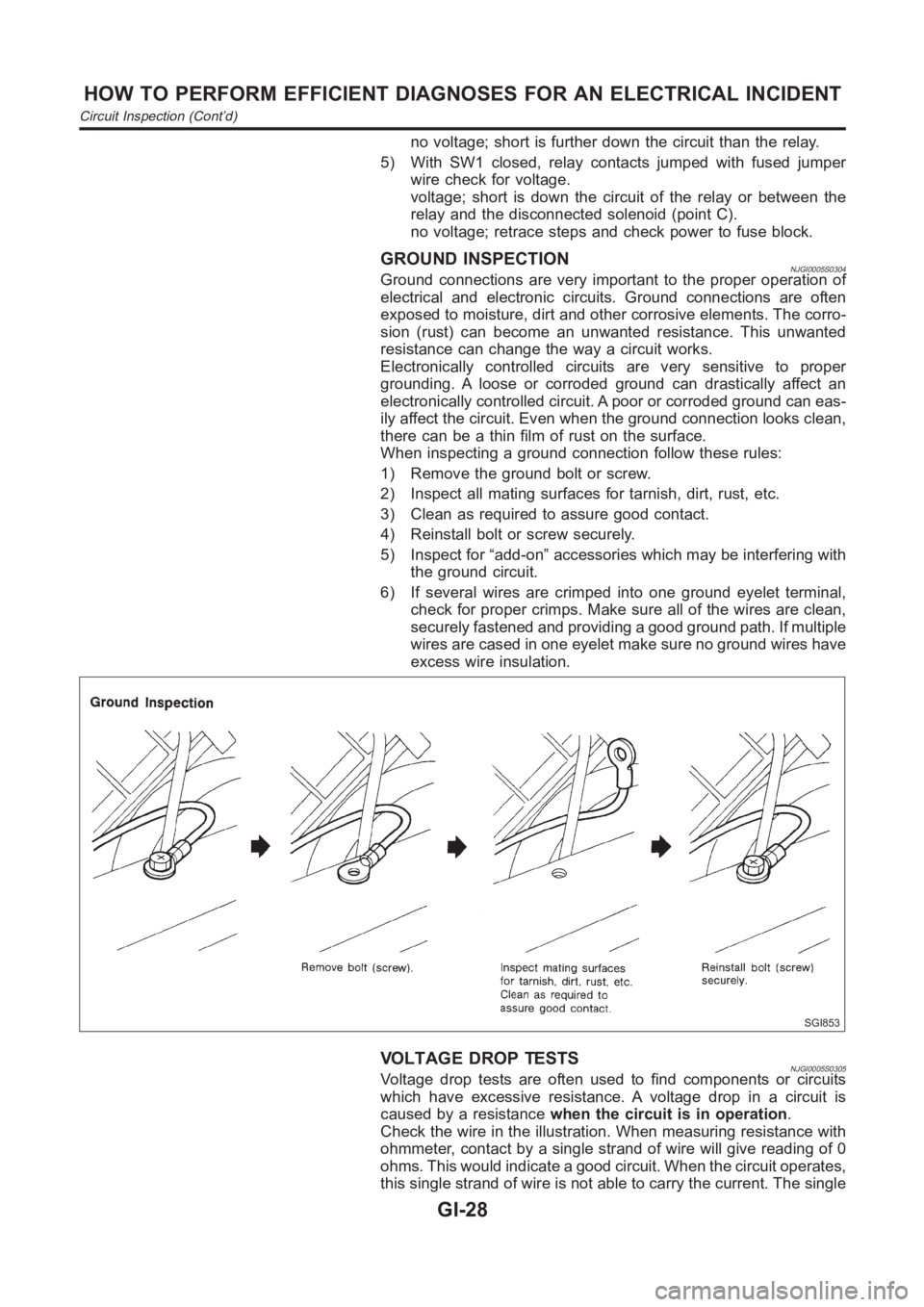
When inspecting a ground connection follow these rules:
1) Remove the ground bolt or screw.
2) Inspect all mating surfaces for tarnish, dirt, rust, etc.
3) Clean as required to assure good contact.
4) Reinstall bolt or screw securely.
5) Inspect for “add-on” accessories which may be interfering with
the ground circuit.
6) If several wires are crimped into one ground eyelet terminal,
check for proper crimps. Make sure all of the wires are clean,
securely fastened and providing a good ground path. If multiple
wires are cased in one eyelet make sure no ground wires have
excess wire insulation.
SGI853
VOLTAGE DROP TESTSNJGI0005S0305Voltage drop tests are often used to find components or circuits
which have excessive resistance. A voltage drop in a circuit is
caused by a resistancewhen the circuit is in operation.
Check the wire in the illustration. When measuring resistance with
ohmmeter, contact by a single strand of wire will give reading of 0
ohms. This would indicate a good circuit. When the circuit operates,
this single strand of wire is not able to carry the current. The single
HOW TO PERFORM EFFICIENT DIAGNOSES FOR AN ELECTRICAL INCIDENT
Circuit Inspection (Cont’d)
GI-28
Page 147 of 3189
ENGINE ASSEMBLY
EM-69
[QG]
C
D
E
F
G
H
I
J
K
L
MA
EM
●Center member
●Front exhaust tube
●Stabilizer bar
●Cooling fan
●Radiator
●Disconnect wires, harness, pipes, hoses and so on.
10. Lift up engine slightly and disconnect or remove all engine
mountings.
When lifting engine, be sure to clear surrounding parts. Use
special care near brake tubes and brake master cylinder.
11. Remove engine with transaxle as shown.
INSTALLATION
●Install in reverse order of removal.
SEM108G
SEM420D
Page 217 of 3189
Removal and InstallationNJEM0109
YEM053
SEM565G
PREPARATIVE WORKNJEM0109S011. Drain engine coolant. Refer to LC-43, “Changing engine cool-
ant”.
2. Remove engine cover. Refer to the figure at left.
3. Remove injection tube.
4. Remove blow-by hose (on rocker cover side).
5. Remove or relocate fuel pipes.
6. Remove or relocate wires/harnesses and tubes/pipes.
GI
MA
LC
EC
FE
CL
MT
AT
AX
SU
BR
ST
RS
BT
HA
SC
EL
IDX
INTAKE MANIFOLDYD
Removal and Installation
EM-33
Page 247 of 3189

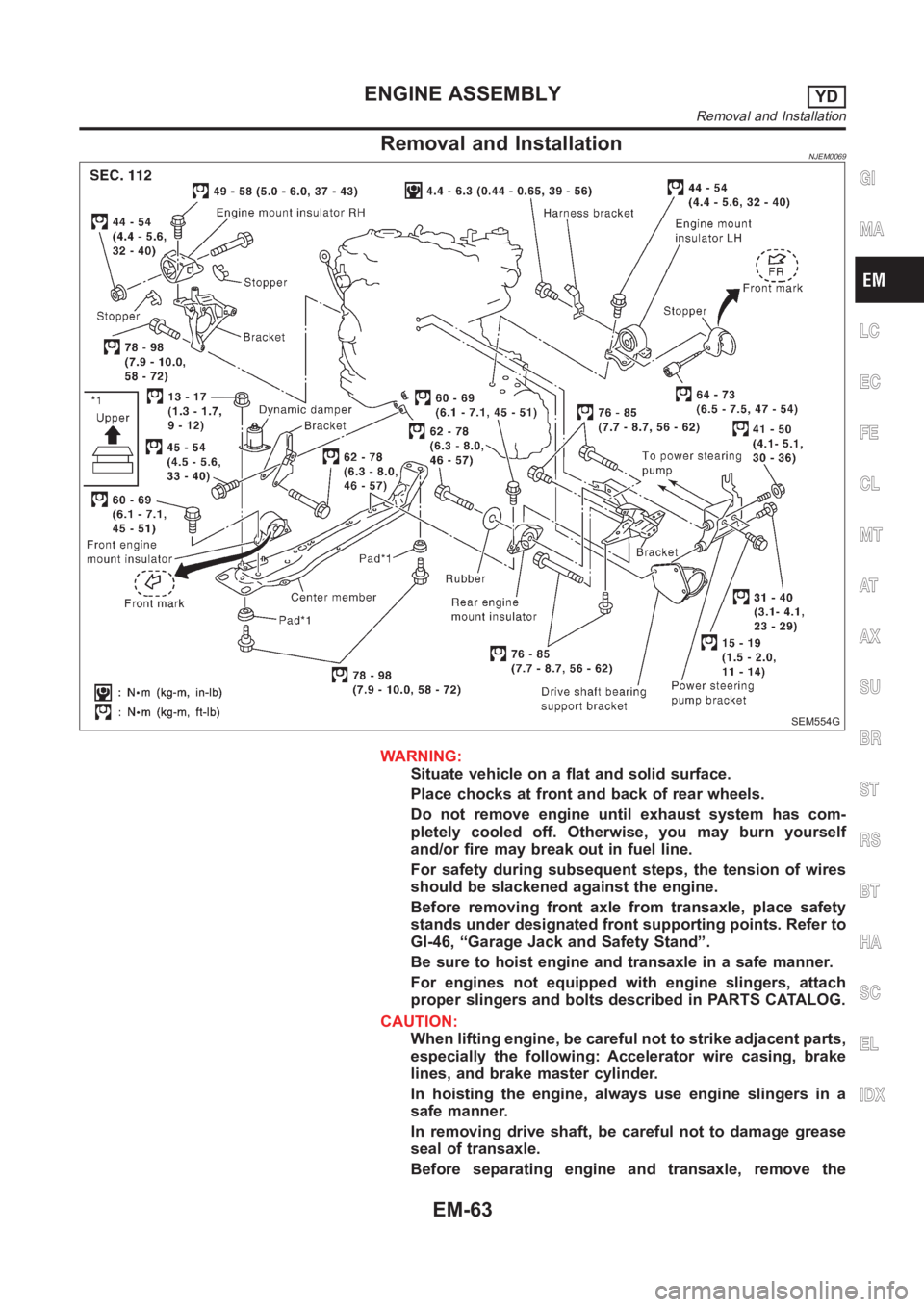
Removal and InstallationNJEM0069
SEM554G
WARNING:
Situate vehicle on a flat and solid surface.
Place chocks at front and back of rear wheels.
Do not remove engine until exhaust system has com-
pletely cooled off. Otherwise, you may burn yourself
and/or fire may break out in fuel line.
For safety during subsequent steps, the tension of wires
should be slackened against the engine.
Before removing front axle from transaxle, place safety
stands under designated front supporting points. Refer to
GI-46, “Garage Jack and Safety Stand”.
Be sure to hoist engine and transaxle in a safe manner.
For engines not equipped with engine slingers, attach
proper slingers and bolts described in PARTS CATALOG.
CAUTION:
When lifting engine, be careful not to strike adjacent parts,
especially the following: Accelerator wire casing, brake
lines, and brake master cylinder.
In hoisting the engine, always use engine slingers in a
safe manner.
In removing drive shaft, be careful not to damage grease
seal of transaxle.
Before separating engine and transaxle, remove the
GI
MA
LC
EC
FE
CL
MT
AT
AX
SU
BR
ST
RS
BT
HA
SC
EL
IDX
ENGINE ASSEMBLYYD
Removal and Installation
EM-63
Page 314 of 3189
![NISSAN ALMERA N16 2003 Electronic Repair Manual SLC428B
REMOVALNJLC0076S011. Using a socket wrench [plane-to-plane width: 17 mm (0.67 in)],
loosen the filter body approximately four turns.
JLC291B
2. Drain the oil after matching the “DRAIN” arr NISSAN ALMERA N16 2003 Electronic Repair Manual SLC428B
REMOVALNJLC0076S011. Using a socket wrench [plane-to-plane width: 17 mm (0.67 in)],
loosen the filter body approximately four turns.
JLC291B
2. Drain the oil after matching the “DRAIN” arr](/manual-img/5/57350/w960_57350-313.png)
SLC428B
REMOVALNJLC0076S011. Using a socket wrench [plane-to-plane width: 17 mm (0.67 in)],
loosen the filter body approximately four turns.
JLC291B
2. Drain the oil after matching the “DRAIN” arrow mark at the
bottom of the filter body to the protrusion on the oil filter
bracket.
Catch the oil with a pan or cloth.
CAUTION:
The drained oil flows over the right surface of the filter
body.
Completely wipe clean any engine oil remaining on the
filter body or vehicle.
3. Remove the filter body, then remove the oil filter element.
JLC292B
4. Remove the O-ring from the filter body.
Push the O-ring in one direction, lift the slack part using
fingers, and remove the O-ring from the filter body.
CAUTION:
Do not use wires or flat-bladed screwdrivers etc. as they may
cause damage to the filter body.
INSTALLATIONNJLC0076S021. Completely remove all foreign objects adhering to the inside of
the filter body or O-ring mounting area (body side and bracket
side).
2. Install the oil filter element and O-ring to the filter body.
Push the oil filter element into the filter body completely.
3. Install the filter body to the oil filter bracket.
: 20 - 24 N·m (2.0 - 2.5 kg-m, 15 - 18 ft-lb)
4. After warming up the engine, check for engine oil leakage.
ENGINE LUBRICATION SYSTEMYD
Changing Oil Filter (Cont’d)
LC-32
Page 360 of 3189
EC-30
[QG (WITH EURO-OBD)]
BASIC SERVICE PROCEDURE
BASIC SERVICE PROCEDURE
PFP:00018
Idle Speed and Ignition Timing CheckEBS00K3A
IDLE SPEED
With CONSULT-II
Check idle speed in “DATA MONITOR” mode with CONSULT-II.
With GST
Check idle speed in “MODE 1” with GST.
IGNITION TIMING
Any of following two methods may be used.
Method A
1. Slide the harness protector of ignition coil No. 1 to clear the wires.
2. Attach timing light to the wires as shown.
3. Check ignition timing.
Method B
1. Remove No. 1 ignition coil.
SEF058Y
MBIB0047E
MBIB0048E