2003 NISSAN ALMERA N16 Diagnostic
[x] Cancel search: DiagnosticPage 8 of 3189
Do not attempt to top off the fuel tank after the fuel pump nozzle
shuts off automatically. Continued refueling may cause fuel
overflow, resulting in fuel spray and possibly a fire.
WARNING:
To prevent ECM from storing the diagnostic trouble codes, do
not carelessly disconnect the harness connectors which are
related to the engine control system and TCM (Transmission
Control Module) system. The connectors should be discon-
nected only when working according to the WORK FLOW of
TROUBLE DIAGNOSES in EC and AT sections.
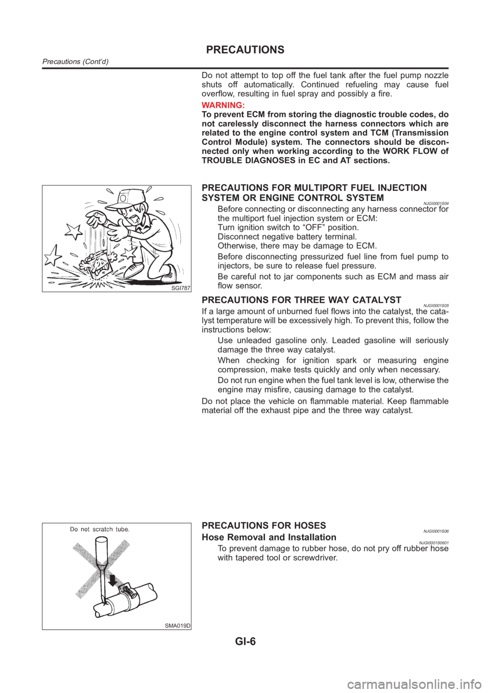
SGI787
PRECAUTIONS FOR MULTIPORT FUEL INJECTION
SYSTEM OR ENGINE CONTROL SYSTEM
NJGI0001S04Before connecting or disconnecting any harness connector for
the multiport fuel injection system or ECM:
Turn ignition switch to “OFF” position.
Disconnect negative battery terminal.
Otherwise, there may be damage to ECM.
Before disconnecting pressurized fuel line from fuel pump to
injectors, be sure to release fuel pressure.
Be careful not to jar components such as ECM and mass air
flow sensor.
PRECAUTIONS FOR THREE WAY CATALYSTNJGI0001S05If a large amount of unburned fuel flows into the catalyst, the cata-
lyst temperature will be excessively high. To prevent this, follow the
instructions below:
Use unleaded gasoline only. Leaded gasoline will seriously
damage the three way catalyst.
When checking for ignition spark or measuring engine
compression, make tests quickly and only when necessary.
Do not run engine when the fuel tank level is low, otherwise the
engine may misfire, causing damage to the catalyst.
Do not place the vehicle on flammable material. Keep flammable
material off the exhaust pipe and the three way catalyst.
SMA019D
PRECAUTIONS FOR HOSESNJGI0001S06Hose Removal and InstallationNJGI0001S0601To prevent damage to rubber hose, do not pry off rubber hose
with tapered tool or screwdriver.
PRECAUTIONS
Precautions (Cont’d)
GI-6
Page 20 of 3189
SGI862-A
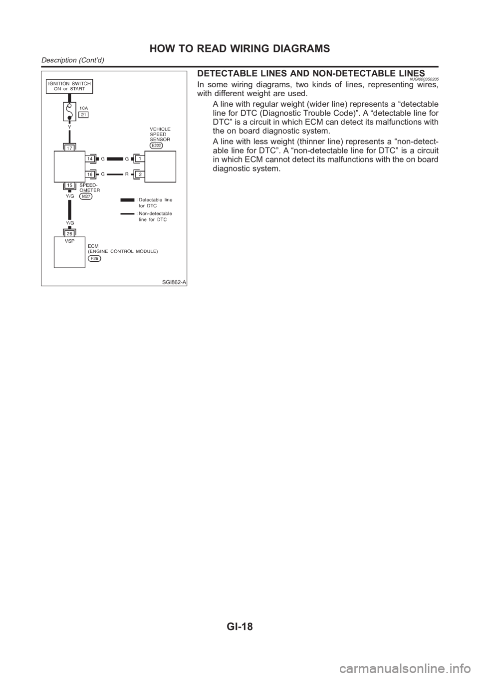
DETECTABLE LINES AND NON-DETECTABLE LINESNJGI0003S0205In some wiring diagrams, two kinds of lines, representing wires,
with different weight are used.
A line with regular weight (wider line) represents a “detectable
line for DTC (Diagnostic Trouble Code)”. A “detectable line for
DTC” is a circuit in which ECM can detect its malfunctions with
the on board diagnostic system.
A line with less weight (thinner line) represents a “non-detect-
able line for DTC”. A “non-detectable line for DTC” is a circuit
in which ECM cannot detect its malfunctions with the on board
diagnostic system.
HOW TO READ WIRING DIAGRAMS
Description (Cont’d)
GI-18
Page 34 of 3189
NJGI0006
NOTICE:
Trouble diagnoses indicate work procedures required to diagnose
problems effectively. Observe the following instructions before
diagnosing.
1)Before performing trouble diagnoses, read the “Prelimi-
nary Check”, the “Symptom Chart” or the “Work Flow”.
2)After repairs, re-check that the problem has been com-
pletely eliminated.
3)Refer to Component Parts and Harness Connector Loca-
tion for the Systems described in each section for
identification/location of components and harness con-
nectors.
4)Refer to the Circuit Diagram for quick pinpoint check.
If you need to check circuit continuity between harness
connectors in more detail, such as when a sub-harness is
used, refer to Wiring Diagram in each individual section
and Harness Layout in EL section for identification of har-
ness connectors.
5)When checking circuit continuity, ignition switch should
be OFF.
6)Before checking voltage at connectors, check battery volt-
age.
7)After accomplishing the Diagnostic Procedures and Elec-
trical Components Inspection, make sure that all harness
connectors are reconnected as they were.
HOW TO FOLLOW TROUBLE DIAGNOSES
GI-32
Page 35 of 3189
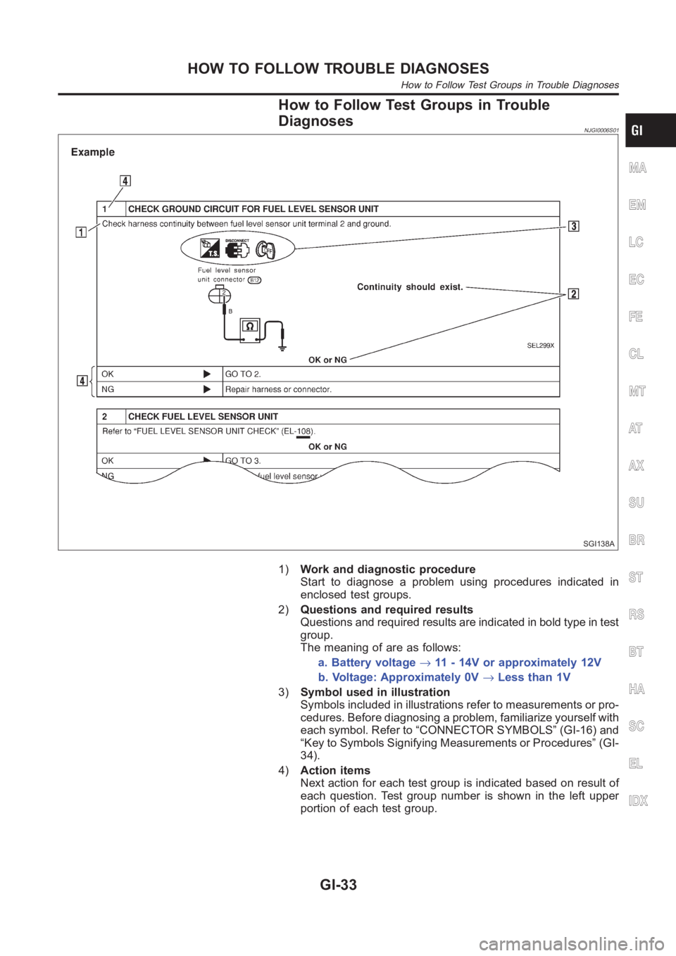
How to Follow Test Groups in Trouble
Diagnoses
NJGI0006S01
SGI138A
1)Work and diagnostic procedure
Start to diagnose a problem using procedures indicated in
enclosed test groups.
2)Questions and required results
Questions and required results are indicated in bold type in test
group.
The meaning of are as follows:
a. Battery voltage→11 - 14V or approximately 12V
b. Voltage: Approximately 0V→Less than 1V
3)Symbol used in illustration
Symbols included in illustrations refer to measurements or pro-
cedures. Before diagnosing a problem, familiarize yourself with
each symbol. Refer to “CONNECTOR SYMBOLS” (GI-16) and
“Key to Symbols Signifying Measurements or Procedures” (GI-
34).
4)Action items
Next action for each test group is indicated based on result of
each question. Test group number is shown in the left upper
portion of each test group.
MA
EM
LC
EC
FE
CL
MT
AT
AX
SU
BR
ST
RS
BT
HA
SC
EL
IDX
HOW TO FOLLOW TROUBLE DIAGNOSES
How to Follow Test Groups in Trouble Diagnoses
GI-33
Page 38 of 3189
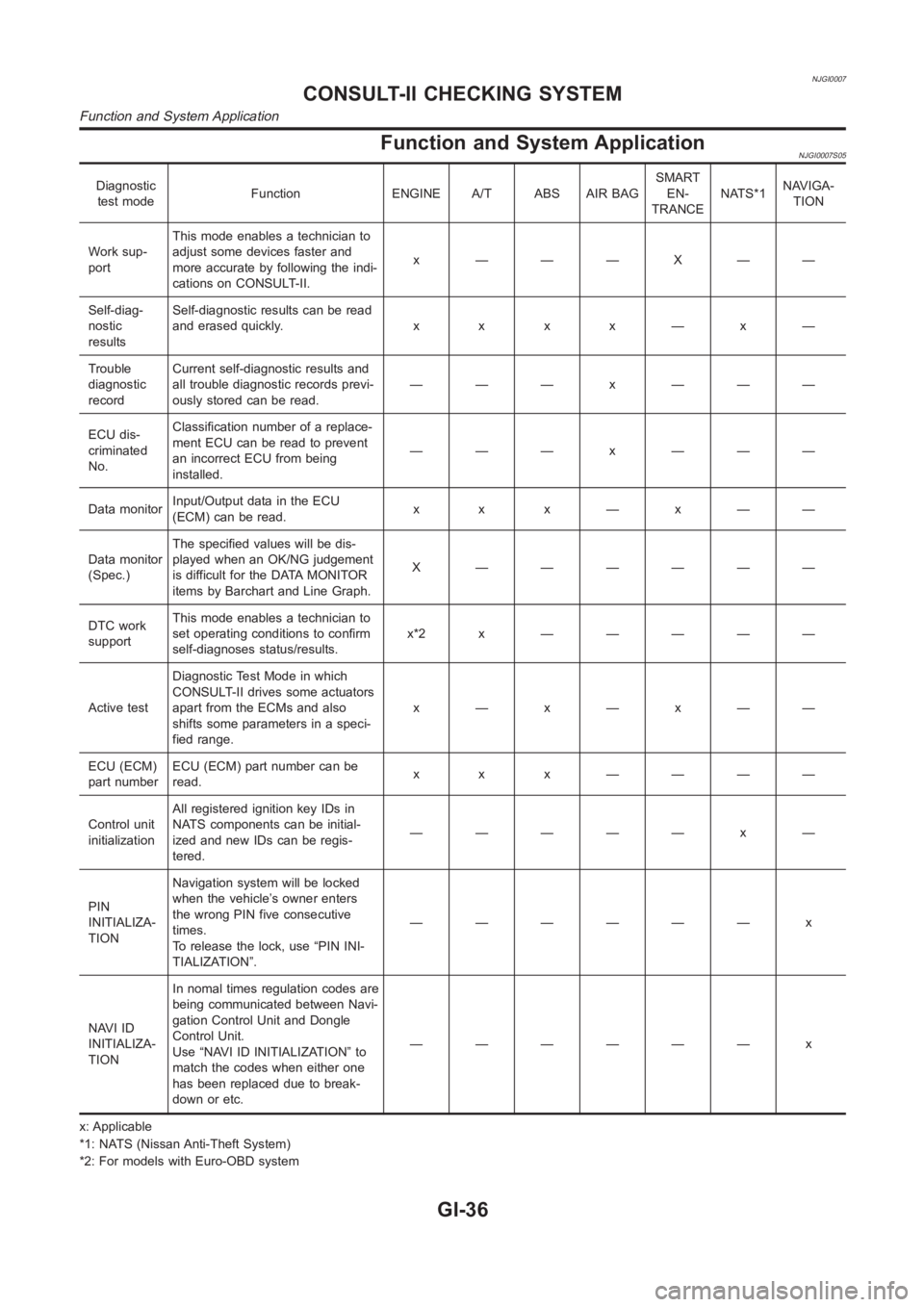
NJGI0007
Function and System ApplicationNJGI0007S05
Diagnostic
test modeFunction ENGINE A/T ABS AIR BAGSMART
EN-
TRANCENATS*1NAVIGA-
TION
Work sup-
portThis mode enables a technician to
adjust some devices faster and
more accurate by following the indi-
cations on CONSULT-II.x ———X——
Self-diag-
nostic
resultsSelf-diagnostic results can be read
anderasedquickly. x x x x—x—
Trouble
diagnostic
recordCurrent self-diagnostic results and
all trouble diagnostic records previ-
ously stored can be read.——— x ———
ECU dis-
criminated
No.Classification number of a replace-
ment ECU can be read to prevent
an incorrect ECU from being
installed.——— x ———
Data monitorInput/Output data in the ECU
(ECM) can be read.x x x—x——
Data monitor
(Spec.)The specified values will be dis-
played when an OK/NG judgement
is difficult for the DATA MONITOR
items by Barchart and Line Graph.X ——————
DTC work
supportThis mode enables a technician to
set operating conditions to confirm
self-diagnoses status/results.x*2x —————
Active testDiagnostic Test Mode in which
CONSULT-II drives some actuators
apart from the ECMs and also
shifts some parameters in a speci-
fied range.x—x—x——
ECU (ECM)
part numberECU (ECM) part number can be
read.x x x ————
Control unit
initializationAll registered ignition key IDs in
NATS components can be initial-
ized and new IDs can be regis-
tered.————— x —
PIN
INITIALIZA-
TIONNavigation system will be locked
when the vehicle’s owner enters
the wrong PIN five consecutive
times.
To release the lock, use “PIN INI-
TIALIZATION”.—————— x
NAVI ID
INITIALIZA-
TIONIn nomal times regulation codes are
being communicated between Navi-
gation Control Unit and Dongle
Control Unit.
Use “NAVI ID INITIALIZATION” to
match the codes when either one
has been replaced due to break-
down or etc.—————— x
x: Applicable
*1: NATS (Nissan Anti-Theft System)
*2: For models with Euro-OBD system
CONSULT-II CHECKING SYSTEM
Function and System Application
GI-36
Page 53 of 3189
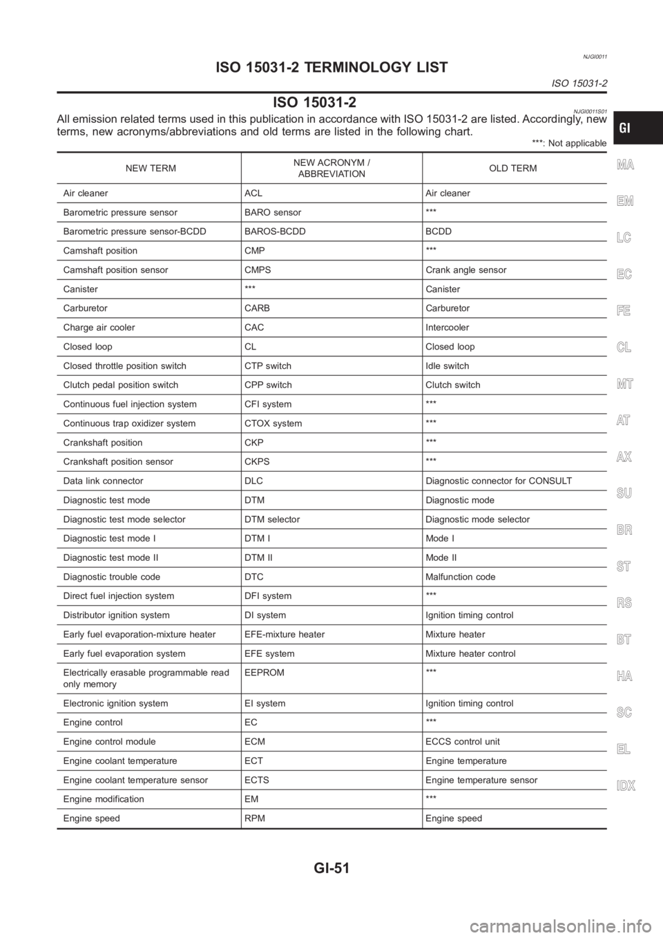
NJGI0011
ISO 15031-2NJGI0011S01All emission related terms used in this publication in accordance with ISO15031-2 are listed. Accordingly, new
terms, new acronyms/abbreviations and old terms are listed in the following chart.
***: Not applicable
NEW TERMNEW ACRONYM /
ABBREVIATIONOLD TERM
Air cleaner ACL Air cleaner
Barometric pressure sensor BARO sensor ***
Barometric pressure sensor-BCDD BAROS-BCDD BCDD
Camshaft position CMP ***
Camshaft position sensor CMPS Crank angle sensor
Canister *** Canister
Carburetor CARB Carburetor
Charge air cooler CAC Intercooler
Closed loop CL Closed loop
Closed throttle position switch CTP switch Idle switch
Clutch pedal position switch CPP switch Clutch switch
Continuous fuel injection system CFI system ***
Continuous trap oxidizer system CTOX system ***
Crankshaft position CKP ***
Crankshaft position sensor CKPS ***
Data link connector DLC Diagnostic connector for CONSULT
Diagnostic test mode DTM Diagnostic mode
Diagnostic test mode selector DTM selector Diagnostic mode selector
Diagnostic test mode I DTM I Mode I
Diagnostic test mode II DTM II Mode II
Diagnostic trouble code DTC Malfunction code
Direct fuel injection system DFI system ***
Distributor ignition system DI system Ignition timing control
Early fuel evaporation-mixture heater EFE-mixture heater Mixture heater
Early fuel evaporation system EFE system Mixture heater control
Electrically erasable programmable read
only memoryEEPROM ***
Electronic ignition system EI system Ignition timing control
Engine control EC ***
Engine control module ECM ECCS control unit
Engine coolant temperature ECT Engine temperature
Engine coolant temperature sensor ECTS Engine temperature sensor
Engine modification EM ***
Engine speed RPM Engine speedMA
EM
LC
EC
FE
CL
MT
AT
AX
SU
BR
ST
RS
BT
HA
SC
EL
IDX
ISO 15031-2 TERMINOLOGY LIST
ISO 15031-2
GI-51
Page 55 of 3189
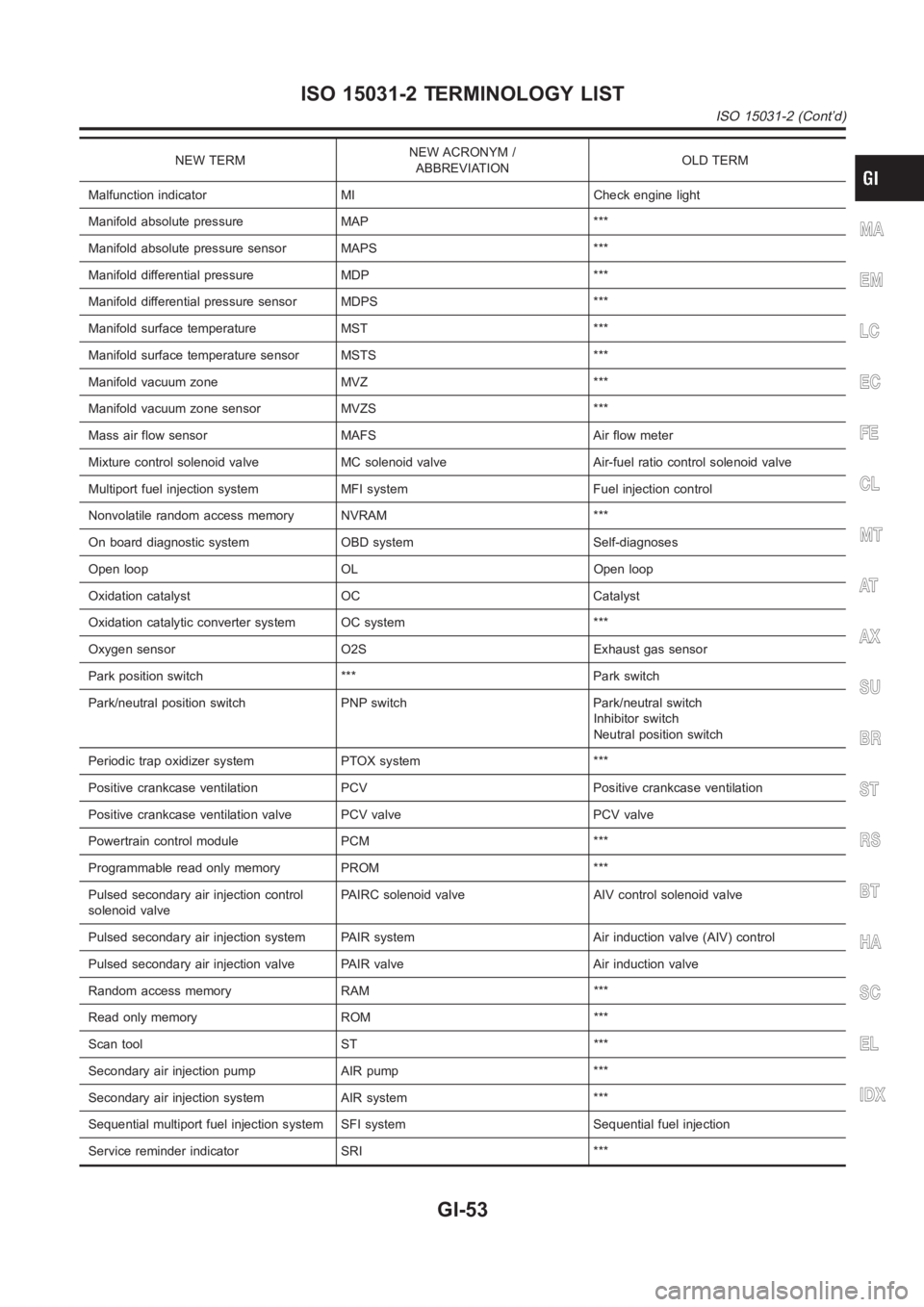
NEW TERMNEW ACRONYM /
ABBREVIATIONOLD TERM
Malfunction indicator MI Check engine light
Manifold absolute pressure MAP ***
Manifold absolute pressure sensor MAPS ***
Manifold differential pressure MDP ***
Manifold differential pressure sensor MDPS ***
Manifold surface temperature MST ***
Manifold surface temperature sensor MSTS ***
Manifold vacuum zone MVZ ***
Manifold vacuum zone sensor MVZS ***
Mass air flow sensor MAFS Air flow meter
Mixture control solenoid valve MC solenoid valve Air-fuel ratio control solenoid valve
Multiport fuel injection system MFI system Fuel injection control
Nonvolatile random access memory NVRAM ***
On board diagnostic system OBD system Self-diagnoses
Open loop OL Open loop
Oxidation catalyst OC Catalyst
Oxidation catalytic converter system OC system ***
Oxygen sensor O2S Exhaust gas sensor
Park position switch *** Park switch
Park/neutral position switch PNP switch Park/neutral switch
Inhibitor switch
Neutral position switch
Periodic trap oxidizer system PTOX system ***
Positive crankcase ventilation PCV Positive crankcase ventilation
Positive crankcase ventilation valve PCV valve PCV valve
Powertrain control module PCM ***
Programmable read only memory PROM ***
Pulsed secondary air injection control
solenoid valvePAIRC solenoid valve AIV control solenoid valve
Pulsed secondary air injection system PAIR system Air induction valve (AIV) control
Pulsed secondary air injection valve PAIR valve Air induction valve
Random access memory RAM ***
Read only memory ROM ***
Scan tool ST ***
Secondary air injection pump AIR pump ***
Secondary air injection system AIR system ***
Sequential multiport fuel injection system SFI system Sequential fuel injection
Service reminder indicator SRI ***
MA
EM
LC
EC
FE
CL
MT
AT
AX
SU
BR
ST
RS
BT
HA
SC
EL
IDX
ISO 15031-2 TERMINOLOGY LIST
ISO 15031-2 (Cont’d)
GI-53
Page 331 of 3189
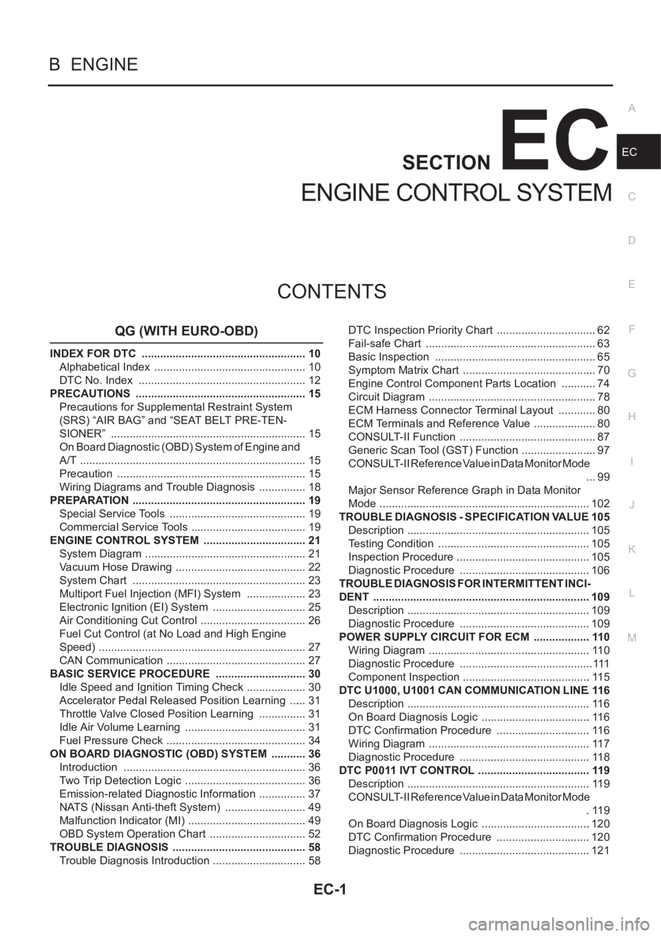
EC-1
ENGINE CONTROL SYSTEM
B ENGINE
CONTENTS
C
D
E
F
G
H
I
J
K
L
M
SECTION
A
EC
ENGINE CONTROL SYSTEM
QG (WITH EURO-OBD)
INDEX FOR DTC ...................................................... 10
Alphabetical Index .................................................. 10
DTC No. Index ....................................................... 12
PRECAUTIONS ........................................................ 15
Precautions for Supplemental Restraint System
(SRS) “AIR BAG” and “SEAT BELT PRE-TEN-
SIONER” ................................................................ 15
On Board Diagnostic (OBD) System of Engine and
A/T .......................................................................... 15
Precaution .............................................................. 15
Wiring Diagrams and Trouble Diagnosis ................ 18
PREPARATION ......................................................... 19
Special Service Tools ............................................. 19
Commercial Service Tools ...................................... 19
ENGINE CONTROL SYSTEM .................................. 21
System Diagram ..................................................... 21
Vacuum Hose Drawing ........................................... 22
System Chart ......................................................... 23
Multiport Fuel Injection (MFI) System .................... 23
Electronic Ignition (EI) System ............................... 25
Air Conditioning Cut Control ................................... 26
Fuel Cut Control (at No Load and High Engine
Speed) .................................................................... 27
CAN Communication .............................................. 27
BASIC SERVICE PROCEDURE .............................. 30
Idle Speed and Ignition Timing Check .................... 30
Accelerator Pedal Released Position Learning ...... 31
Throttle Valve Closed Position Learning ................ 31
Idle Air Volume Learning ........................................ 31
Fuel Pressure Check .............................................. 34
ON BOARD DIAGNOSTIC (OBD) SYSTEM ............ 36
Introduction ............................................................ 36
Two Trip Detection Logic ........................................ 36
Emission-related Diagnostic Information ................ 37
NATS (Nissan Anti-theft System) ........................... 49
Malfunction Indicator (MI) ....................................... 49
OBD System Operation Chart ................................ 52
TROUBLE DIAGNOSIS ............................................ 58
Trouble Diagnosis Introduction ............................... 58DTC Inspection Priority Chart ................................. 62
Fail-safe Chart ........................................................ 63
Basic Inspection ..................................................... 65
Symptom Matrix Chart ............................................ 70
Engine Control Component Parts Location ............ 74
Circuit Diagram ....................................................... 78
ECM Harness Connector Terminal Layout ............. 80
ECM Terminals and Reference Value ..................
... 80
CONSULT-II Function ............................................. 87
Generic Scan Tool (GST) Function ......................... 97
CONSULT-II Reference Value in Data Monitor Mode
... 99
Major Sensor Reference Graph in Data Monitor
Mode .....................................................................102
TROUBLE DIAGNOSIS - SPECIFICATION VALUE .105
Description ............................................................105
Testing Condition ..................................................105
Inspection Procedure ............................................105
Diagnostic Procedure ...........................................106
TROUBLE DIAGNOSIS FOR INTERMITTENT INCI-
DENT .......................................................................109
Description ............................................................109
Diagnostic Procedure ...........................................109
POWER SUPPLY CIRCUIT FOR ECM ...................110
Wiring Diagram .....................................................110
Diagnostic Procedure ............................................111
Component Inspection ..........................................115
DTC U1000, U1001 CAN COMMUNICATION LINE .116
Description ............................................................116
On Board Diagnosis Logic ....................................116
DTC Confirmation Procedure ...............................116
Wiring Diagram .....................................................117
Diagnostic Procedure ...........................................118
DTC P0011 IVT CONTROL .....................................119
Description ............................................................119
CONSULT-II Reference Value in Data Monitor Mode
.119
On Board Diagnosis Logic ....................................120
DTC Confirmation Procedure ...............................120
Diagnostic Procedure ...........................................121