Page 1347 of 3189
SMT940D
SMT951D
21. Pick up EGI harness clamp and install engine slinger. Next, set
chain block.
22. Jack up the air compressor engine bracket.
23. Remove engine front mounting.
24. Remove LH side mounting. Refer to EM-67, “Removal and
Installation”.
SMT952D
25. Jack up until engine oil filter bracket bolts are just about to
touch the side frame.
SMT941D
26. Remove bolts securing transaxle.
27. While the transaxle is suspended, withdraw the transaxle case
from the engine without hitting suspension member.
Open the front of the transaxle when the clutch cover
appears. Then, lower the transaxle pulling it toward the
right front.
The spacer between the engine and transaxle should be
left at the engine side.
28. Remove spacer.
GI
MA
EM
LC
EC
FE
CL
AT
AX
SU
BR
ST
RS
BT
HA
SC
EL
IDX
REMOVAL AND INSTALLATIONRS5F50A
Removal (Cont’d)
MT-27
Page 1348 of 3189
SMT941D
InstallationNJMT0090S021. Put transaxle under the engine compartment.
2. Set chain block on transaxle and hang.
3. Lift up transaxle case so as not to hit against the side frame
and suspension member.
4. Assemble transaxle to engine.
Tighten LH mount, rear side mount and center member bolts.
Refer to EM-67, “Removal and Installation”.
Tighten clutch operating cylinder bolts. Refer to CL-15, “Instal-
lation”.
Tighten starter motor bolts. Refer to SC-22, “Removal and
Installation”.
Install drive shafts. Refer to AX-12, “Installation”.
Tighten all transaxle bolts and any part removed.
SMT932D
MODEL YD ENGINENJMT0090S0201
Bolt No. Tightening torque N·m (kg-m, ft-lb) “�” mm (in)
140 - 49 (4.0 - 5.0, 29 - 36) 70 (2.76)
230.4 - 36.3 (3.1 - 3.7, 23 - 26) 60 (2.36)
330.4 - 36.3 (3.1 - 3.7, 23 - 26) 55 (2.17)
REMOVAL AND INSTALLATIONRS5F50A
Installation
MT-28
Page 1350 of 3189
NJMT0039
Case ComponentsNJMT0039S01
SMT956DA
1. Clutch housing
2. Input shaft oil seal
3. Oil pocket
4. Bearing retainer
5. Torx screw
6. Filler plug
7. Air breather tube
8. Welch plug
9. O-ring10. Case cover
11. Back-up lamp switch
12. Differential oil seal
13. Drain plug
14. Transmission case
15. Oil gutter
16. Reverse idler shaft
17. Oil channel
18. Striking rod oil seal19. Boot
20. Differential oil seal
21. O-ring
22. Speedometer pinion assembly
23. Magnet
24. Earth term
25. Welch plug
26. Welch plug
27. PNP switch
OVERHAULRS5F30A
Case Components
MT-30
Page 1353 of 3189

NJMT0040
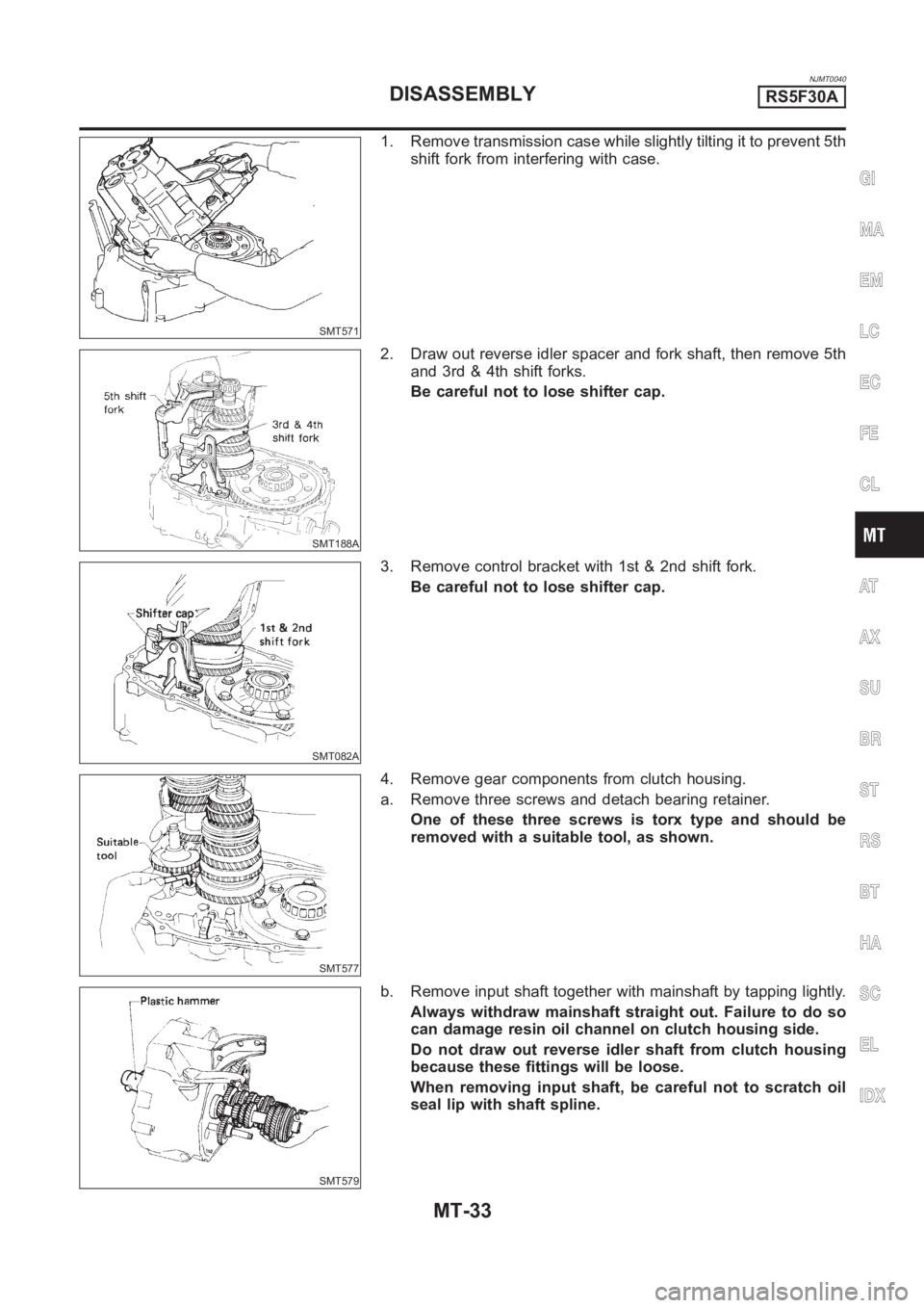
SMT571
1. Remove transmission case while slightly tilting it to prevent 5th
shift fork from interfering with case.
SMT188A
2. Draw out reverse idler spacer and fork shaft, then remove 5th
and 3rd & 4th shift forks.
Be careful not to lose shifter cap.
SMT082A
3. Remove control bracket with 1st & 2nd shift fork.
Be careful not to lose shifter cap.
SMT577
4. Remove gear components from clutch housing.
a. Remove three screws and detach bearing retainer.
One of these three screws is torx type and should be
removed with a suitable tool, as shown.
SMT579
b. Remove input shaft together with mainshaft by tapping lightly.
Always withdraw mainshaft straight out. Failure to do so
can damage resin oil channel on clutch housing side.
Do not draw out reverse idler shaft from clutch housing
because these fittings will be loose.
When removing input shaft, be careful not to scratch oil
seal lip with shaft spline.
GI
MA
EM
LC
EC
FE
CL
AT
AX
SU
BR
ST
RS
BT
HA
SC
EL
IDX
DISASSEMBLYRS5F30A
MT-33
Page 1354 of 3189
SMT580
c. Remove reverse idler gear and final drive assembly.
SMT648AA
5. Remove oil pocket, shift check ball, shift check spring and
check ball plug.
SMT599AA
6. Drive retaining pin out of striking lever, then remove striking
rod, striking lever and striking interlock.
Select a position where retaining pin does not interfere
with clutch housing when removing retaining pin.
SMT583
Be careful not to damage oil seal lip, when removing strik-
ing rod. If necessary, tape edges of striking rod.
SMT584
7. Remove reverse check plug, then detach reverse check spring
and check balls.
DISASSEMBLYRS5F30A
MT-34
Page 1369 of 3189

NJMT0091
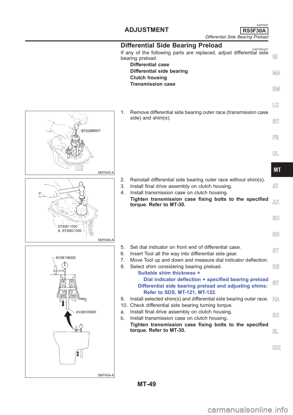
Differential Side Bearing PreloadNJMT0091S01If any of the following parts are replaced, adjust differential side
bearing preload.
Differential case
Differential side bearing
Clutch housing
Transmission case
SMT645-A
1. Remove differential side bearing outer race (transmission case
side) and shim(s).
SMT646-A
2. Reinstall differential side bearing outer race without shim(s).
3. Install final drive assembly on clutch housing.
4. Install transmission case on clutch housing.
Tighten transmission case fixing bolts to the specified
torque. Refer to MT-30.
SMT454-A
5. Set dial indicator on front end of differential case.
6. Insert Tool all the way into differential side gear.
7. Move Tool up and down and measure dial indicator deflection.
8. Select shim considering bearing preload.
Suitable shim thickness =
Dial indicator deflection + specified bearing preload
Differential side bearing preload and adjusting shims:
Refer to SDS, MT-121, MT-122.
9. Install selected shim(s) and differential side bearing outer race.
10. Check differential side bearing turning torque.
a. Install final drive assembly on clutch housing.
b. Install transmission case on clutch housing.
Tighten transmission case fixing bolts to the specified
torque. Refer to MT-30.
GI
MA
EM
LC
EC
FE
CL
AT
AX
SU
BR
ST
RS
BT
HA
SC
EL
IDX
ADJUSTMENTRS5F30A
Differential Side Bearing Preload
MT-49
Page 1370 of 3189

SMT600-A
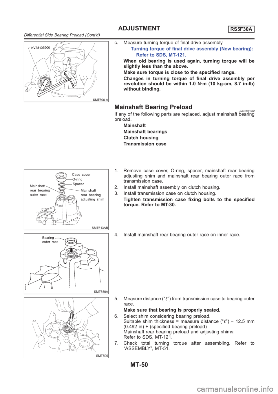
c. Measure turning torque of final drive assembly.
Turning torque of final drive assembly (New bearing):
Refer to SDS, MT-121.
When old bearing is used again, turning torque will be
slightly less than the above.
Make sure torque is close to the specified range.
Changes in turning torque of final drive assembly per
revolution should be within 1.0 N·m (10 kg-cm, 8.7 in-lb)
without binding.
Mainshaft Bearing PreloadNJMT0091S02If any of the following parts are replaced, adjust mainshaft bearing
preload.
Mainshaft
Mainshaft bearings
Clutch housing
Transmission case
SMT613AB
1. Remove case cover, O-ring, spacer, mainshaft rear bearing
adjusting shim and mainshaft rear bearing outer race from
transmission case.
2. Install mainshaft assembly on clutch housing.
3. Install transmission case on clutch housing.
Tighten transmission case fixing bolts to the specified
torque. Refer to MT-30.
SMT650A
4. Install mainshaft rear bearing outer race on inner race.
SMT599
5. Measure distance (“�”) from transmission case to bearing outer
race.
Make sure that bearing is properly seated.
6. Select shim considering bearing preload.
Suitable shim thickness = measure distance (“�”) − 12.5 mm
(0.492 in) + (specified bearing preload)
Mainshaft rear bearing preload and adjusting shims:
Refer to SDS, MT-121.
7. Check total turning torque after assembling. Refer to
“ASSEMBLY”, MT-51.
ADJUSTMENTRS5F30A
Differential Side Bearing Preload (Cont’d)
MT-50
Page 1371 of 3189

NJMT0092
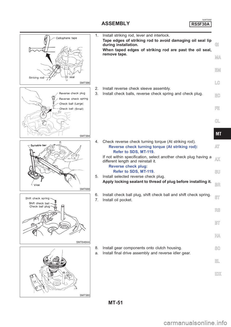
SMT586
1. Install striking rod, lever and interlock.
Tape edges of striking rod to avoid damaging oil seal lip
during installation.
When taped edges of striking rod are past the oil seal,
remove tape.
SMT584
2. Install reverse check sleeve assembly.
3. Install check balls, reverse check spring and check plug.
SMT688
4. Check reverse check turning torque (At striking rod).
Reverse check turning torque (At striking rod):
Refer to SDS, MT-119.
If not within specification, select another check plug having a
different length and reinstall it.
Reverse check plug:
Refer to SDS, MT-119.
5. Install selected reverse check plug.
Apply locking sealant to thread of plug before installing it.
SMT648AA
6. Install check ball plug, shift check ball and shift check spring.
7. Install oil pocket.
SMT580
8. Install gear components onto clutch housing.
a. Install final drive assembly and reverse idler gear.
GI
MA
EM
LC
EC
FE
CL
AT
AX
SU
BR
ST
RS
BT
HA
SC
EL
IDX
ASSEMBLYRS5F30A
MT-51