2003 NISSAN ALMERA N16 navigation
[x] Cancel search: navigationPage 38 of 3189
NJGI0007
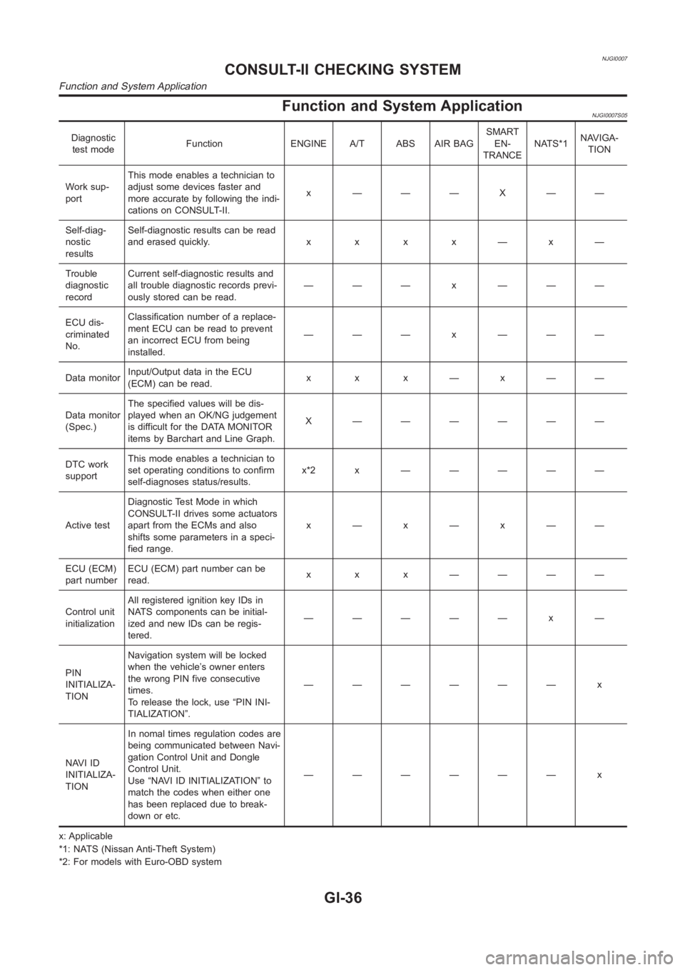
Function and System ApplicationNJGI0007S05
Diagnostic
test modeFunction ENGINE A/T ABS AIR BAGSMART
EN-
TRANCENATS*1NAVIGA-
TION
Work sup-
portThis mode enables a technician to
adjust some devices faster and
more accurate by following the indi-
cations on CONSULT-II.x ———X——
Self-diag-
nostic
resultsSelf-diagnostic results can be read
anderasedquickly. x x x x—x—
Trouble
diagnostic
recordCurrent self-diagnostic results and
all trouble diagnostic records previ-
ously stored can be read.——— x ———
ECU dis-
criminated
No.Classification number of a replace-
ment ECU can be read to prevent
an incorrect ECU from being
installed.——— x ———
Data monitorInput/Output data in the ECU
(ECM) can be read.x x x—x——
Data monitor
(Spec.)The specified values will be dis-
played when an OK/NG judgement
is difficult for the DATA MONITOR
items by Barchart and Line Graph.X ——————
DTC work
supportThis mode enables a technician to
set operating conditions to confirm
self-diagnoses status/results.x*2x —————
Active testDiagnostic Test Mode in which
CONSULT-II drives some actuators
apart from the ECMs and also
shifts some parameters in a speci-
fied range.x—x—x——
ECU (ECM)
part numberECU (ECM) part number can be
read.x x x ————
Control unit
initializationAll registered ignition key IDs in
NATS components can be initial-
ized and new IDs can be regis-
tered.————— x —
PIN
INITIALIZA-
TIONNavigation system will be locked
when the vehicle’s owner enters
the wrong PIN five consecutive
times.
To release the lock, use “PIN INI-
TIALIZATION”.—————— x
NAVI ID
INITIALIZA-
TIONIn nomal times regulation codes are
being communicated between Navi-
gation Control Unit and Dongle
Control Unit.
Use “NAVI ID INITIALIZATION” to
match the codes when either one
has been replaced due to break-
down or etc.—————— x
x: Applicable
*1: NATS (Nissan Anti-Theft System)
*2: For models with Euro-OBD system
CONSULT-II CHECKING SYSTEM
Function and System Application
GI-36
Page 2023 of 3189
TROUBLE DIAGNOSIS
ATC-43
C
D
E
F
G
H
I
K
L
MA
B
AT C
FUNCTION CONFIRMATION PROCEDURE
1.SET IN SELF-DIAGNOSTIC MODE
Method 1 (Without navigation system, or with navigation system)
1. Turn ignition switch to ON.
2. Within 10 seconds after starting engine (ignition switch is turned ON.), press and hold OFF switch for at
least 5 seconds.
3. The self-diagnosis (step 1) should start.
Method 2 (Only with navigation system)
1. Turn OFF the audio system.
2. While pressing “Vehicle Information” switch, turn audio switch (volume adjustment dial) by at least 30
notches.
3. Trouble diagnosis initial screen appears. Using joystick, select “Confirmation and Adjustment”. And press
“Confirm”.
4. Confirmation and adjustment initial screen appears. Using joystick, select “Air-conditioner trouble diagno-
sis”, and press “Confirm” to start self-diagnosis (step 1).
CAUTION:
If battery voltage drops below 12V during step diagnosis 3, actuator speed becomes slower and as a
result, the system may generate an error even when operation is normal. To avoid this, start engine
before performing this diagnosis.
>> GO TO 2.
Page 2091 of 3189
TROUBLE DIAGNOSIS
ATC-111
C
D
E
F
G
H
I
K
L
MA
B
AT C
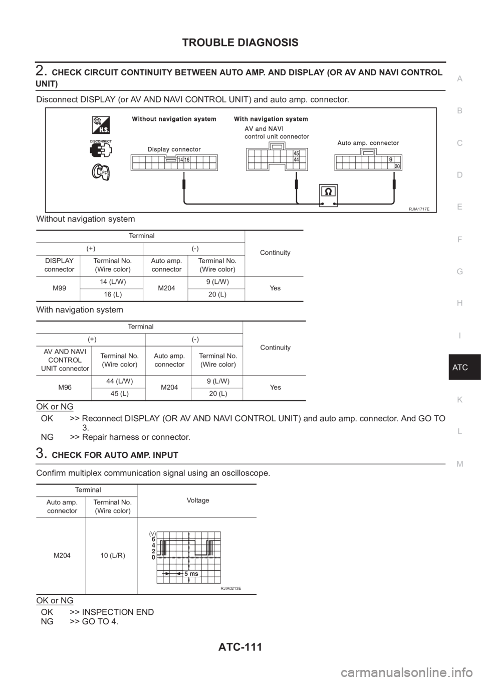
2.CHECK CIRCUIT CONTINUITY BETWEEN AUTO AMP. AND DISPLAY (OR AV AND NAVI CONTROL
UNIT)
Disconnect DISPLAY (or AV AND NAVI CONTROL UNIT) and auto amp. connector.
Without navigation system
With navigation system
OK or NG
OK >> Reconnect DISPLAY (OR AV AND NAVI CONTROL UNIT) and auto amp. connector. And GO TO
3.
NG >> Repair harness or connector.
3.CHECK FOR AUTO AMP. INPUT
Confirm multiplex communication signal using an oscilloscope.
OK or NG
OK >> INSPECTION END
NG >> GO TO 4.
Terminal
Continuity (+) (-)
DISPLAY
connectorTerminal No.
(Wire color)Auto amp.
connectorTerminal No.
(Wire color)
M9914 (L/W)
M2049 (L/W)
Ye s
16 (L) 20 (L)
Terminal
Continuity (+) (-)
AV AND NAVI
CONTROL
UNIT connectorTerminal No.
(Wire color)Auto amp.
connectorTe r m i n a l N o .
(Wire color)
M9644 (L/W)
M2049 (L/W)
Ye s
45 (L) 20 (L)
RJIA1717E
Te r m i n a l
Voltage
Auto amp.
connectorTerminal No.
(Wire color)
M204 10 (L/R)
RJIA0213E
Page 2092 of 3189
ATC-112
TROUBLE DIAGNOSIS
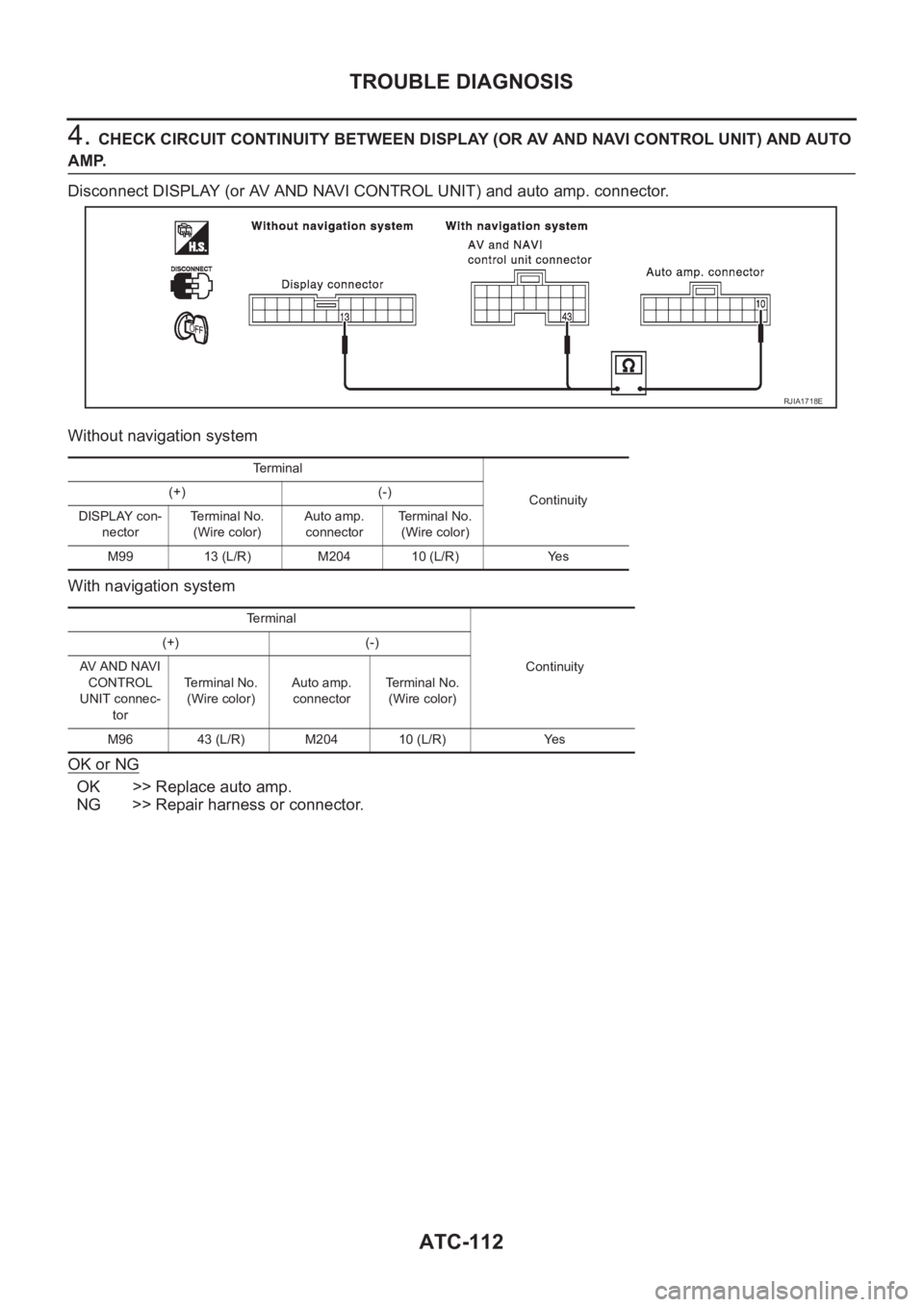
4. CHECK CIRCUIT CONTINUITY BETWEEN DISPLAY (OR AV AND NAVI CONTROL UNIT) AND AUTO
AMP.
Disconnect DISPLAY (or AV AND NAVI CONTROL UNIT) and auto amp. connector.
Without navigation system
With navigation system
OK or NG
OK >> Replace auto amp.
NG >> Repair harness or connector.
RJIA1718E
Terminal
Continuity (+) (-)
DISPLAY con-
nectorTerminal No.
(Wire color)Auto amp.
connectorTerminal No.
(Wire color)
M99 13 (L/R) M204 10 (L/R) Yes
Terminal
Continuity (+) (-)
AV AND NAVI
CONTROL
UNIT connec-
torTerminal No.
(Wire color)Auto amp.
connectorTerminal No.
(Wire color)
M96 43 (L/R) M204 10 (L/R) Yes
Page 2339 of 3189
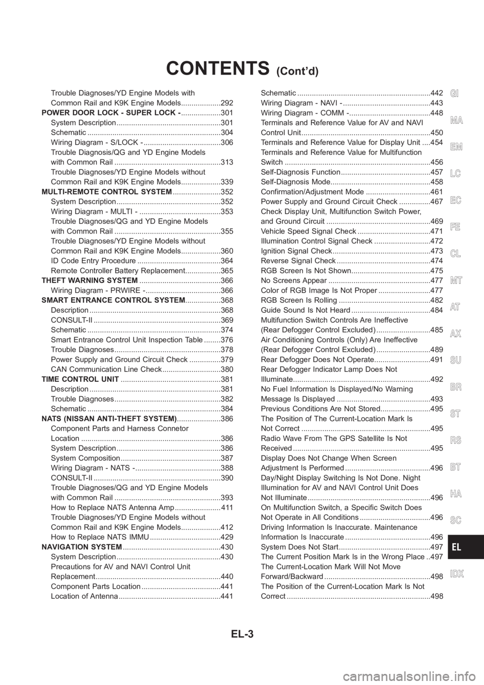
Trouble Diagnoses/YD Engine Models with
Common Rail and K9K Engine Models...................292
POWER DOOR LOCK - SUPER LOCK -...................301
System Description ..................................................301
Schematic <0011001100110011001100110011001100110011001100110011001100110011001100110011001100110011001100110011001100110011001100110011001100110011001100110011001100110011001100110011001100110011001100110011001100
11001100110011[..........304
Wiring Diagram - S/LOCK - .....................................306
Trouble Diagnosis/QG and YD Engine Models
with Common Rail ...................................................313
Trouble Diagnoses/YD Engine Models without
Common Rail and K9K Engine Models...................339
MULTI-REMOTE CONTROL SYSTEM.......................352
System Description ..................................................352
Wiring Diagram - MULTI - .......................................353
Trouble Diagnoses/QG and YD Engine Models
with Common Rail ...................................................355
Trouble Diagnoses/YD Engine Models without
Common Rail and K9K Engine Models...................360
ID Code Entry Procedure ........................................364
Remote Controller Battery Replacement.................365
THEFT WARNING SYSTEM.......................................366
Wiring Diagram - PRWIRE -....................................366
SMART ENTRANCE CONTROL SYSTEM.................368
Description <0011001100110011001100110011001100110011001100110011001100110011001100110011001100110011001100110011001100110011001100110011001100110011001100110011001100110011001100110011001100110011001100110011001100
110011[...........368
CONSULT-II <0011001100110011001100110011001100110011001100110011001100110011001100110011001100110011001100110011001100110011001100110011001100110011001100110011001100110011001100110011001100110011001100110011001100
1100110011[........369
Schematic <0011001100110011001100110011001100110011001100110011001100110011001100110011001100110011001100110011001100110011001100110011001100110011001100110011001100110011001100110011001100110011001100110011001100
11001100110011[..........374
Smart Entrance Control Unit Inspection Table ........376
Trouble Diagnoses...................................................378
Power Supply and Ground Circuit Check ...............379
CAN Communication Line Check ............................380
TIME CONTROL UNIT................................................381
Description <0011001100110011001100110011001100110011001100110011001100110011001100110011001100110011001100110011001100110011001100110011001100110011001100110011001100110011001100110011001100110011001100110011001100
110011[...........381
Trouble Diagnoses...................................................382
Schematic <0011001100110011001100110011001100110011001100110011001100110011001100110011001100110011001100110011001100110011001100110011001100110011001100110011001100110011001100110011001100110011001100110011001100
11001100110011[..........384
NATS (NISSAN ANTI-THEFT SYSTEM).....................386
Component Parts and Harness Connetor
Location <0011001100110011001100110011001100110011001100110011001100110011001100110011001100110011001100110011001100110011001100110011001100110011001100110011001100110011001100110011001100110011001100110011001100
110011001100110011[............386
System Description ..................................................386
System Composition ................................................387
Wiring Diagram - NATS -.........................................388
CONSULT-II <0011001100110011001100110011001100110011001100110011001100110011001100110011001100110011001100110011001100110011001100110011001100110011001100110011001100110011001100110011001100110011001100110011001100
1100110011[........390
Trouble Diagnoses/QG and YD Engine Models
with Common Rail ...................................................393
How to Replace NATS Antenna Amp ...................... 411
Trouble Diagnoses/YD Engine Models without
Common Rail and K9K Engine Models...................412
How to Replace NATS IMMU ..................................429
NAVIGATION SYSTEM...............................................430
System Description ..................................................430
Precautions for AV and NAVI Control Unit
Replacement <0011001100110011001100110011001100110011001100110011001100110011001100110011001100110011001100110011001100110011001100110011001100110011001100110011001100110011001100110011001100110011001100110011001100
110011[........440
Component Parts Location ......................................441
Location of Antenna .................................................441Schematic <0011001100110011001100110011001100110011001100110011001100110011001100110011001100110011001100110011001100110011001100110011001100110011001100110011001100110011001100110011001100110011001100110011001100
11001100110011[..........442
Wiring Diagram - NAVI - ..........................................443
Wiring Diagram - COMM -.......................................448
Terminals and Reference Value for AV and NAVI
Control Unit <0011001100110011001100110011001100110011001100110011001100110011001100110011001100110011001100110011001100110011001100110011001100110011001100110011001100110011001100110011001100110011001100110011001100
110011[..........450
Terminals and Reference Value for Display Unit ....454
Terminals and Reference Value for Multifunction
Switch <0011001100110011001100110011001100110011001100110011001100110011001100110011001100110011001100110011001100110011001100110011001100110011001100110011001100110011001100110011001100110011001100110011001100
11001100110011001100110011[.............456
Self-Diagnosis Function ...........................................457
Self-Diagnosis Mode................................................458
Confirmation/Adjustment Mode ...............................461
Power Supply and Ground Circuit Check ...............467
Check Display Unit, Multifunction Switch Power,
and Ground Circuit ..................................................469
Vehicle Speed Signal Check ...................................471
Illumination Control Signal Check ...........................472
Ignition Signal Check ...............................................473
Reverse Signal Check .............................................474
RGB Screen Is Not Shown......................................475
No Screens Appear .................................................477
Color of RGB Image Is Not Proper .........................477
RGB Screen Is Rolling ............................................482
Guide Sound Is Not Heard ......................................484
Multifunction Switch Controls Are Ineffective
(Rear Defogger Control Excluded) ..........................485
Air Conditioning Controls (Only) Are Ineffective
(Rear Defogger Control Excluded) ..........................489
Rear Defogger Does Not Operate...........................491
Rear Defogger Indicator Lamp Does Not
Illuminate<0011001100110011001100110011001100110011001100110011001100110011001100110011001100110011001100110011001100110011001100110011001100110011001100110011001100110011001100110011001100110011001100110011001100
1100110011[.............492
No Fuel Information Is Displayed/No Warning
Message Is Displayed .............................................493
Previous Conditions Are Not Stored........................495
The Position of The Current-Location Mark Is
Not Correct <0011001100110011001100110011001100110011001100110011001100110011001100110011001100110011001100110011001100110011001100110011001100110011001100110011001100110011001100110011001100110011001100110011001100
1100110011[.........495
Radio Wave From The GPS Satellite Is Not
Received <0011001100110011001100110011001100110011001100110011001100110011001100110011001100110011001100110011001100110011001100110011001100110011001100110011001100110011001100110011001100110011001100110011001100
110011001100110011[...........495
Display Does Not Change When Screen
Adjustment Is Performed .........................................496
Day/Night Display Switching Is Not Done. Night
Illumination for AV and NAVI Control Unit Does
Not Illuminate ...........................................................496
On Multifunction Switch, a Specific Switch Does
Not Operate in All Conditions ..................................496
Driving Information Is Inaccurate. Maintenance
Information Is Inaccurate .........................................496
System Does Not Start ............................................497
The Current Position Mark Is in the Wrong Place ..497
The Current-Location Mark Will Not Move
Forward/Backward ...................................................498
The Position of the Current-Location Mark Is Not
Correct <0011001100110011001100110011001100110011001100110011001100110011001100110011001100110011001100110011001100110011001100110011001100110011001100110011001100110011001100110011001100110011001100110011001100
1100110011001100110011[.............498
GI
MA
EM
LC
EC
FE
CL
MT
AT
AX
SU
BR
ST
RS
BT
HA
SC
IDX
CONTENTS(Cont’d)
EL-3
Page 2528 of 3189
System Description=NJEL0497AUDIO SYSTEM WITHOUT DISPLAYNJEL0497S08Refer to Owner’s Manual for audio system operating instructions.
Power is supplied at all times
through 15A fuse (No. 40, located in the fusible link and fuse block)
to audio unit terminal 9.
With the ignition switch in the ACC or ON position, power is supplied
through 10A fuse [No. 1, located in the fuse block (J/B)]
to audio unit terminal 3.
Ground is supplied through the case of the audio unit.
Audio signals are supplied
through audio unit terminals 7, 10, 11, 12, 13, 14, 15, 16
to terminals 1 and 2 of front door speaker LH and RH,
to terminals 1 and 2 of rear door speaker LH and RH and
to terminals 1 and 2 of pillar tweeter LH and RH (with 6 speakers)
AUDIO SYSTEM WITH DISPLAYNJEL0497S09Refer to Owner’s Manual for audio system operating instructions.
Power is supplied at all times
through 15A fuse (No. 40, located in the fuse and fusible link box)
to audio unit terminals 3 and 4, and
to display terminals 21 and 23.
With the ignition switch in the ACC or ON position, power is supplied
through 10A fuse [No. 1, located in the fuse block (J/B)]
to audio unit terminal 2,
to multifunction switch terminal 6 and
to display terminal 19.
Ground is supplied through the case of the audio unit.
Ground is also supplied
through body grounds M28, M67 and F118 (QG engine models)
to multifunction switch terminal 1 and
to display terminals 22 and 24.
Audio signals are supplied
through audio unit terminals 5, 6, 7, 8, 9, 10, 11, 12
to terminals 1 and 2 of front door speaker LH and RH
to terminals 1 and 2 of rear door speaker LH and RH
to terminals 1 and 2 of tweeter LH and RH
AV COMMUNICATION LINENJEL0497S10Audio system is contained and the AV communication line is connected as followings.
Display unit terminals 12 and 13, and
Multifunction switch terminals 12 and 14.
Multifunction switch terminals 11 and 13, and
Audio unit terminals 31 and 32.
Audio unit terminals 35 and 36, and
AV and NAVI control unit terminals 47 and 48 (with navigation system).
The operation is controlled by operation signals from multifunction switch, then audio screen is displayed.
NAVIGATION SYSTEM OF GUIDANCE VOICE OPERATIONNJEL0497S11When navigation system is used, guidance voice signal is supplied
from AV and NAVI control unit terminals 7 and 8
to audio unit terminals 35 and 36.
Navigation system of guidance voice will be sounded.
AUDIO
System Description
EL-192
Page 2529 of 3189
NATS AUDIO LINKNJEL0497S12DescriptionNJEL0497S1201The link with the NATS IMMU implies that the audio unit can basically only beoperated if connected to the
matching NATS IMMU to which the audio unit was initially fitted on the production line.
Since radio operation is impossible after the link with the NATS is disrupted theft of the audio unit is basically
useless since special equipment is required to reset the audio unit.
Initialization process for audio units that are linked to the NATS IMMU
Perform initialization with CONSULT-II
For initialization, refer to “CONSULT-II operation manual NATS”.
Normal operation
Each time the audio unit is switched on afterwards, the audio unit code willbe verified between the audio unit
and the NATS before the audio unit becomes operational.
When the radio is locked
When NATS link problems occur “SECURE” message will be displayed in three ways indicating three differ-
ent NATS link problems.
“Secure” on a red background indicates that there is a problem in the link between Navi control unit and Audio,
suggesting that there is either a Navigation system fault or the Navi control unit has previously been fitted in
another vehicle.
“Secure” on a green background indicates that there is a problem in the linkbetween NATS IMMU and Audio,
suggesting that there is an audio fault or the audio unit has previously been fitted in another vehicle.
“Secure” on a yellow background indicates that the transponder (NATS key)is not working correctly or it has
previously been fitted in another vehicle.
When a “Secure” message (of any type) is displayed, it can be cleared by re-initializing the NATS system using
CONSULT-II and the associated Immobilizer PIN code (there is no need to return the audio to a Clarion ser-
vice centre). If re-initializing fails to clear a “Secure” message then the component (identified by background
color) is faulty and should be replaced.
NOTE:
When the “Secure” is displayed on VFD display or audio unit, the communication of IMMU and radio, radio
unit or transponder has problem.
Service ProcedureNJEL0497S1202
Item Service procedure Description
Battery disconnection No additional action required. —
Radio needs repair Repair needs to be done by authorized
representative of radio manufacturer since
radio cannot be operated unless it is reset
to NEW state, using special decoding
equipment.—
Replacement of radio by new part No additional action required. Radio is delivered in NEW state.
Transferring radio to another vehicle/
replacement of radio by an “old” partRadio needs to be reset by using CON-
SULT-II and the associated Immobi PIN
code (there is no need to return the audio
or Navi units to a Clarion service centre).—
Replacement of IMMU The communication between IMMU and
radio need to be reset by using CON-
SULT-II and the associated Immobi PIN
code.After switching on the radio, it will display
“SECURE” on a green background.
No communication from IMMU to radio 1. If NATS is malfunctioning, check NATS
system.
2. After NATS is repaired, reset radio to
“Secure” on a green background state
by using CONSULT-II and the associ-
ated Immobilizer PIN code (there is no
need to return the audio to a Clarion
service centre).After switching on the radio, the display
unit will display “SECURE” on a green
background. Further use of radio is
impossible until communication is estab-
lished again, or after radio is reset by
using CONSULT-II and the associated
Immobilizer PIN code (there is no need to
return the audio to a Clarion service cen-
tre).
GI
MA
EM
LC
EC
FE
CL
MT
AT
AX
SU
BR
ST
RS
BT
HA
SC
IDX
AUDIO
System Description (Cont’d)
EL-193
Page 2574 of 3189
System DescriptionNJEL0571MULTIFUNCTION SWITCH SYSTEMNJEL0571S01Refer to Owner′s Manual for multifunction switch operating instruc-
tions.
Using the multifunction switch at the center of the instrument panel,
the controls of the following systems are centralized:
Auto A/C system
Vehicle information system
Audio system
Navigation system
PRECAUTION OF LCD MONITORNJEL0571S02When passenger compartment temperature is low, the LCD
monitor sometimes dims because of the brightness of the back
light (small fluorescent light) integrated into the LCD monitor
decrease. In this case, the refreshing rate of the picture also
becomes low because of the low response of the LCD moni-
tor. When passenger compartment becomes warm, however,
the LCD recovers the normal display.
Sometimes, black or bright dots peculiar to LCD monitor can
be seen on the display.
Back light sometimes flickers or darkens according to the total
consumption hours and the number of ON and OFF switching.
In this case, the back light should be replaced (display unit
assembly).
POWER SUPPLY AND GROUNDNJEL0571S03Power is Supplied at All TimesNJEL0571S0301through 15A fuse (No. 40, located in fuse and fusible link box)
to display unit terminals 21 and 23
to audio unit terminals 3 and 4.
When Ignition Switch is in ACC or ON Position, Power
is Supplied
NJEL0571S0302through 10A fuse [No. 1, located in fuse block (J/B)]
to display unit terminal 19,
to multifunction switch terminal 6 and
to audio unit terminal 2.
When Ignition Switch is in ON or START Position,
Power is Supplied
NJEL0571S0303through 10A fuse [No. 10, located in fuse block (J/B)]
to display unit terminal 27.
Ground is SuppliedNJEL0571S0304to multifunction switch terminal 1 and
to display unit terminals 22 and 24
through body grounds M28, M67 and F118 (QG engine mod-
els).
AV COMMUNICATION LINENJEL0571S04Display unit is controlled by the following unit with AV communica-
tion line.
Multifunction switch
Audio unit
AV and NAVI control unit
LCD DISPLAY
System Description
EL-238