Page 2789 of 3189
Terminal No. (wire
color)
ItemSignal
input/
outputCondition
VoltageExample of symp-
tom
+−Ignition
switchOperation
45 (L) groundA/C clock
signalInput ON —
SKIA0174E
A/C status is not
indicated correctly.
46 (B) —Shield
ground—— — — —
47 (R) groundCommunica-
tion signal
(+)Input/
outputON —
SKIA0175E
System does not
work properly.
48 (G) groundCommunica-
tion signal
(-)Input/
outputON —
SKIA0176E
System does not
work properly.
66 67 GPS signal Input ONConnector is not
connected.Approx. 5 VNavigation system
GPS correction is
not possible.
GI
MA
EM
LC
EC
FE
CL
MT
AT
AX
SU
BR
ST
RS
BT
HA
SC
IDX
NAVIGATION SYSTEM
Terminals and Reference Value for AV and NAVI Control Unit (Cont’d)
EL-453
Page 2790 of 3189
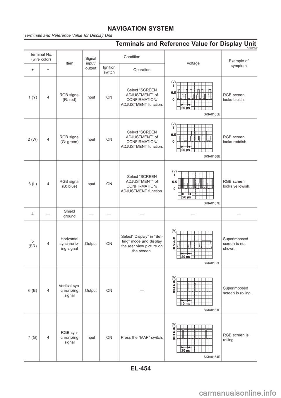
Terminals and Reference Value for Display UnitNJEL0600
Terminal No.
(wire color)
ItemSignal
input/
outputCondition
VoltageExample of
symptom
+−Ignition
switchOperation
1 (Y) 4RGB signal
(R: red)Input ONSelect “SCREEN
ADJUSTMENT” of
CONFIRMATION/
ADJUSTMENT function.
SKIA0165E
RGB screen
looks bluish.
2(W) 4RGB signal
(G: green)Input ONSelect “SCREEN
ADJUSTMENT” of
CONFIRMATION/
ADJUSTMENT function.
SKIA0166E
RGB screen
looks reddish.
3(L) 4RGB signal
(B: blue)Input ONSelect “SCREEN
ADJUSTMENT” of
CONFIRMATION/
ADJUSTMENT function.
SKIA0167E
RGB screen
looks yellowish.
4—Shield
ground—— — — —
5
(BR)4Horizontal
synchroniz-
ing signalOutput ONSelect“ Display” in “Set-
ting” mode and display
the rear view picture on
the screen.
SKIA0163E
Superimposed
screen is not
shown.
6 (B) 4Vertical syn-
chronizing
signalOutput ON —
SKIA0161E
Superimposed
screen is rolling.
7(G) 4RGB syn-
chronizing
signalInput ON Press the “MAP” switch.
SKIA0164E
RGB screen is
rolling.
NAVIGATION SYSTEM
Terminals and Reference Value for Display Unit
EL-454
Page 2791 of 3189
Terminal No.
(wire color)
ItemSignal
input/
outputCondition
VoltageExample of
symptom
+−Ignition
switchOperation
8(R) 4RGB area
signalInput ON Press the “info” switch.
SKIA0162E
RGB screen is
not shown.
12
(W)groundCommunica-
tion signal
(-)Input/
outputON —
SKIA0176E
System does not
work properly.
13 (B) groundCommunica-
tion signal
(+)Input/
outputON —
SKIA0175E
System does not
work properly.
14 —Shield
ground—— — — —
19 (P) ground ACC signal Input ACC — Battery voltageScreen is not
shown.
21 (Y)
groundBattery
powerInput OFF — Battery voltageScreen is not
shown.
23 (Y)
22 (B) ground Ground — ON — Approx. 0V —
24 (B) ground Ground — ON — Approx. 0V —
GI
MA
EM
LC
EC
FE
CL
MT
AT
AX
SU
BR
ST
RS
BT
HA
SC
IDX
NAVIGATION SYSTEM
Terminals and Reference Value for Display Unit (Cont’d)
EL-455
Page 2792 of 3189
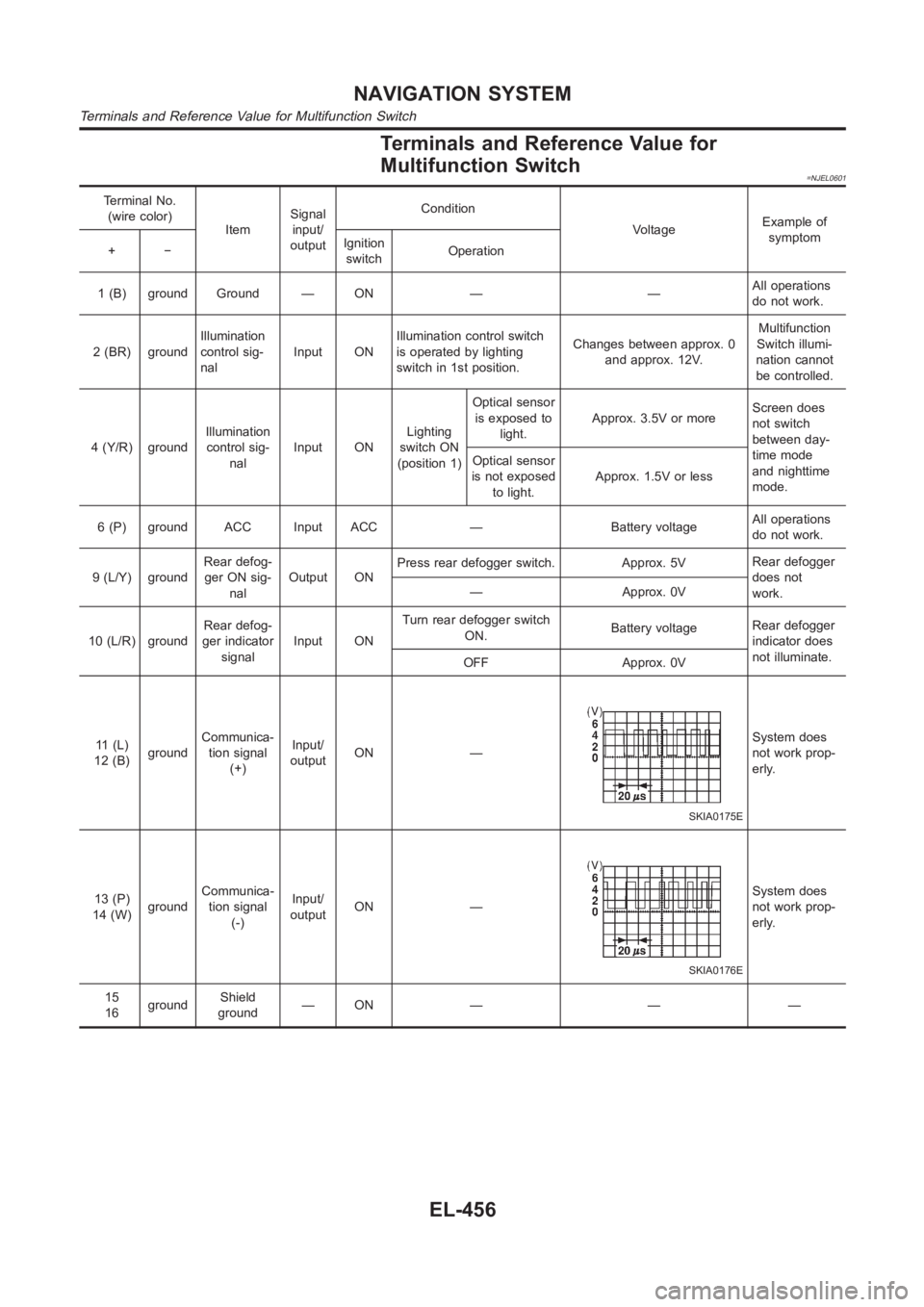
Terminals and Reference Value for
Multifunction Switch
=NJEL0601
Terminal No.
(wire color)
ItemSignal
input/
outputCondition
VoltageExample of
symptom
+−Ignition
switchOperation
1 (B) ground Ground — ON — —All operations
do not work.
2 (BR) groundIllumination
control sig-
nalInput ONIllumination control switch
is operated by lighting
switch in 1st position.Changes between approx. 0
and approx. 12V.Multifunction
Switch illumi-
nation cannot
be controlled.
4 (Y/R) groundIllumination
control sig-
nalInput ONLighting
switch ON
(position 1)Optical sensor
is exposed to
light.Approx. 3.5V or moreScreen does
not switch
between day-
time mode
and nighttime
mode. Optical sensor
is not exposed
to light.Approx. 1.5V or less
6 (P) ground ACC Input ACC — Battery voltageAll operations
do not work.
9 (L/Y) groundRear defog-
ger ON sig-
nalOutput ONPress rear defogger switch. Approx. 5VRear defogger
does not
work. — Approx. 0V
10 (L/R) groundRear defog-
ger indicator
signalInput ONTurn rear defogger switch
ON.Battery voltageRear defogger
indicator does
not illuminate.
OFF Approx. 0V
11 (L)
12 (B)groundCommunica-
tion signal
(+)Input/
outputON —
SKIA0175E
System does
not work prop-
erly.
13 (P)
14 (W)groundCommunica-
tion signal
(-)Input/
outputON —
SKIA0176E
System does
not work prop-
erly.
15
16groundShield
ground—ON — — —
NAVIGATION SYSTEM
Terminals and Reference Value for Multifunction Switch
EL-456
Page 2793 of 3189
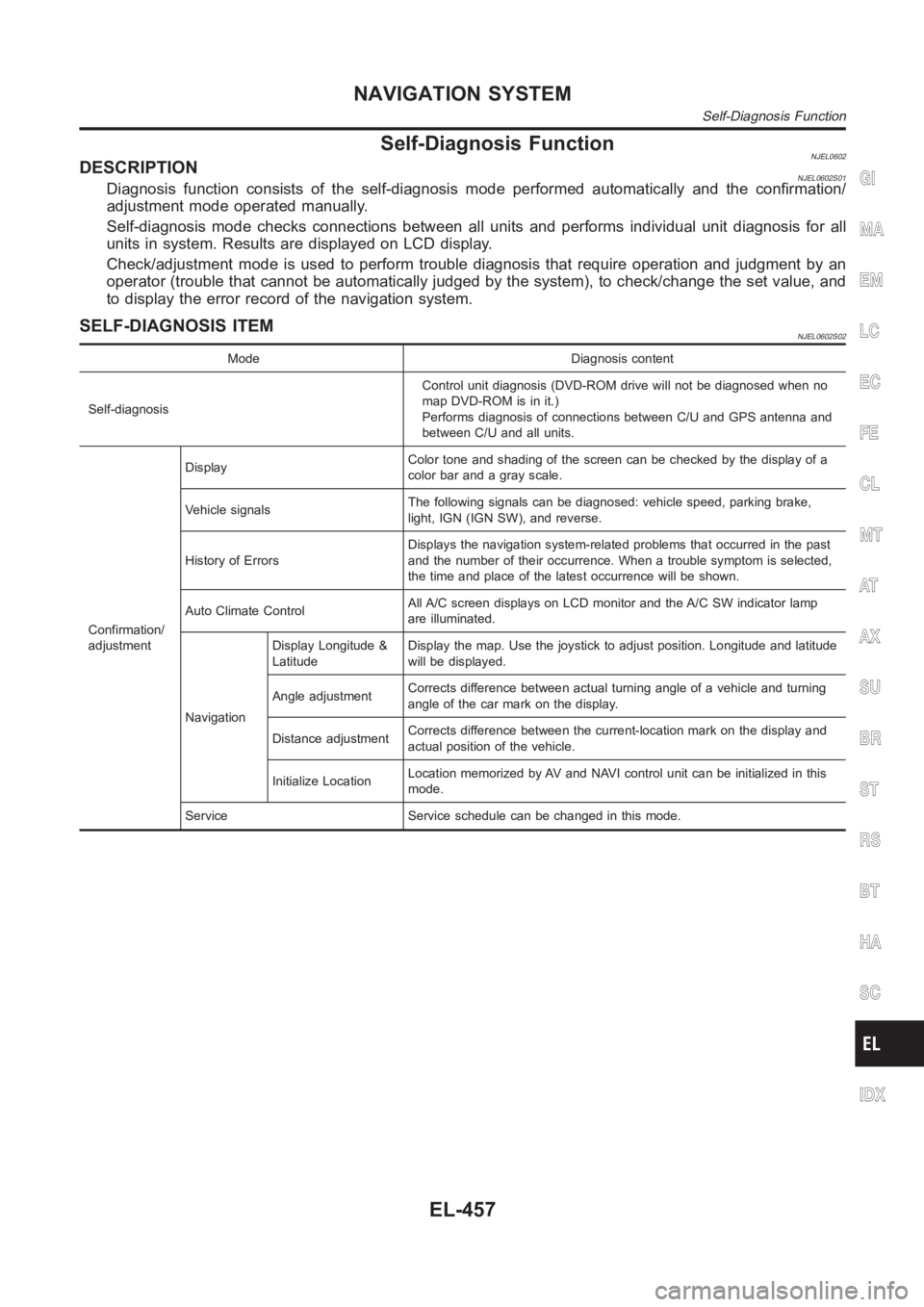
Self-Diagnosis FunctionNJEL0602DESCRIPTIONNJEL0602S01Diagnosis function consists of the self-diagnosis mode performed automatically and the confirmation/
adjustment mode operated manually.
Self-diagnosis mode checks connections between all units and performs individual unit diagnosis for all
units in system. Results are displayed on LCD display.
Check/adjustment mode is used to perform trouble diagnosis that require operation and judgment by an
operator (trouble that cannot be automatically judged by the system), to check/change the set value, and
to display the error record of the navigation system.
SELF-DIAGNOSIS ITEMNJEL0602S02
Mode Diagnosis content
Self-diagnosisControl unit diagnosis (DVD-ROM drive will not be diagnosed when no
map DVD-ROM is in it.)
Performs diagnosis of connections between C/U and GPS antenna and
between C/U and all units.
Confirmation/
adjustmentDisplayColor tone and shading of the screen can be checked by the display of a
color bar and a gray scale.
Vehicle signalsThe following signals can be diagnosed: vehicle speed, parking brake,
light, IGN (IGN SW), and reverse.
History of ErrorsDisplays the navigation system-related problems that occurred in the past
and the number of their occurrence. When a trouble symptom is selected,
the time and place of the latest occurrence will be shown.
Auto Climate ControlAll A/C screen displays on LCD monitor and the A/C SW indicator lamp
are illuminated.
NavigationDisplay Longitude &
LatitudeDisplay the map. Use the joystick to adjust position. Longitude and latitude
will be displayed.
Angle adjustmentCorrects difference between actual turning angle of a vehicle and turning
angle of the car mark on the display.
Distance adjustmentCorrects difference between the current-location mark on the display and
actual position of the vehicle.
Initialize LocationLocation memorized by AV and NAVI control unit can be initialized in this
mode.
Service Service schedule can be changed in this mode.
GI
MA
EM
LC
EC
FE
CL
MT
AT
AX
SU
BR
ST
RS
BT
HA
SC
IDX
NAVIGATION SYSTEM
Self-Diagnosis Function
EL-457
Page 2794 of 3189
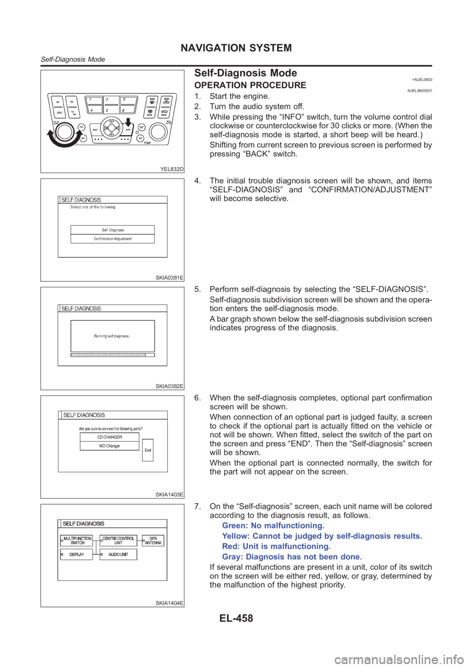
YEL832D
Self-Diagnosis Mode=NJEL0603OPERATION PROCEDURENJEL0603S011. Start the engine.
2. Turn the audio system off.
3. While pressing the “INFO” switch, turn the volume control dial
clockwise or counterclockwise for 30 clicks or more. (When the
self-diagnosis mode is started, a short beep will be heard.)
Shifting from current screen to previous screen is performed by
pressing “BACK” switch.
SKIA0381E
4. The initial trouble diagnosis screen will be shown, and items
“SELF-DIAGNOSIS” and “CONFIRMATION/ADJUSTMENT”
will become selective.
SKIA0382E
5. Perform self-diagnosis by selecting the “SELF-DIAGNOSIS”.
Self-diagnosis subdivision screen will be shown and the opera-
tion enters the self-diagnosis mode.
A bar graph shown below the self-diagnosis subdivision screen
indicates progress of the diagnosis.
SKIA1403E
6. When the self-diagnosis completes, optional part confirmation
screen will be shown.
When connection of an optional part is judged faulty, a screen
to check if the optional part is actually fitted on the vehicle or
not will be shown. When fitted, select the switch of the part on
the screen and press “END”. Then the “Self-diagnosis” screen
will be shown.
When the optional part is connected normally, the switch for
the part will not appear on the screen.
SKIA1404E
7. On the “Self-diagnosis” screen, each unit name will be colored
according to the diagnosis result, as follows.
Green: No malfunctioning.
Yellow: Cannot be judged by self-diagnosis results.
Red: Unit is malfunctioning.
Gray: Diagnosis has not been done.
If several malfunctions are present in a unit, color of its switch
on the screen will be either red, yellow, or gray, determined by
the malfunction of the highest priority.
NAVIGATION SYSTEM
Self-Diagnosis Mode
EL-458
Page 2795 of 3189
SKIA1516E
8. Select a switch on the “Self-diagnosis” screen and comments
for the diagnosis results will be shown.
When the switch is green, the following comment will be
shown. “Self-diagnosis was successful. Further diagnosis and
adjustments are recommended. Follow the “confirmation and
adjustments” menu or refer to the service manual”.
When the switch is yellow, the following comment will be
shown. “Connection to the following unit is abnormal. See the
service manual for further details”.
When the switch is red, the following comment will be shown.
“Center Control Unit is abnormal”.
When the switch is gray, the following comment will be shown.
“Self-diagnosis for DVD-ROM DRIVER of NAVI was not con-
ducted because no DVD-ROM was available”.
GI
MA
EM
LC
EC
FE
CL
MT
AT
AX
SU
BR
ST
RS
BT
HA
SC
IDX
NAVIGATION SYSTEM
Self-Diagnosis Mode (Cont’d)
EL-459
Page 2796 of 3189
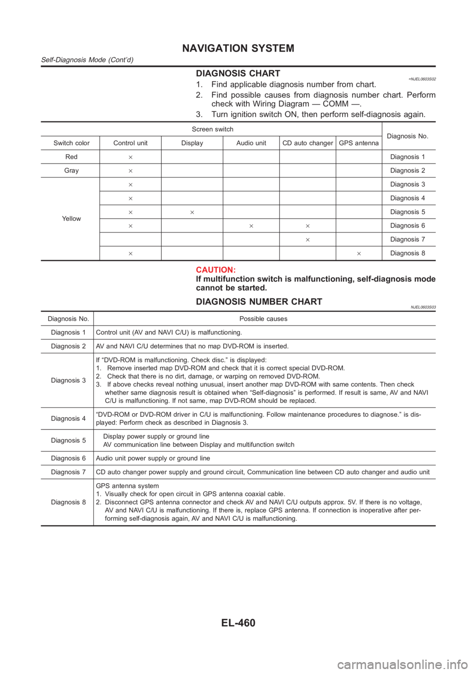
DIAGNOSIS CHART=NJEL0603S021. Find applicable diagnosis number from chart.
2. Find possible causes from diagnosis number chart. Perform
check with Wiring Diagram — COMM —.
3. Turn ignition switch ON, then perform self-diagnosis again.
Screen switch
Diagnosis No.
Switch color Control unit Display Audio unit CD auto changer GPS antenna
Red×Diagnosis 1
Gray×Diagnosis 2
Yellow×Diagnosis 3
×Diagnosis 4
××Diagnosis 5
×××Diagnosis 6
×Diagnosis 7
××Diagnosis 8
CAUTION:
If multifunction switch is malfunctioning, self-diagnosis mode
cannot be started.
DIAGNOSIS NUMBER CHARTNJEL0603S03
Diagnosis No. Possible causes
Diagnosis 1 Control unit (AV and NAVI C/U) is malfunctioning.
Diagnosis 2 AV and NAVI C/U determines that no map DVD-ROM is inserted.
Diagnosis 3If “DVD-ROM is malfunctioning. Check disc.” is displayed:
1. Remove inserted map DVD-ROM and check that it is correct special DVD-ROM.
2. Check that there is no dirt, damage, or warping on removed DVD-ROM.
3. If above checks reveal nothing unusual, insert another map DVD-ROM withsame contents. Then check
whether same diagnosis result is obtained when “Self-diagnosis” is performed. If result is same, AV and NAVI
C/U is malfunctioning. If not same, map DVD-ROM should be replaced.
Diagnosis 4“DVD-ROM or DVD-ROM driver in C/U is malfunctioning. Follow maintenance procedures to diagnose.” is dis-
played: Perform check as described in Diagnosis 3.
Diagnosis 5Display power supply or ground line
AV communication line between Display and multifunction switch
Diagnosis 6 Audio unit power supply or ground line
Diagnosis 7 CD auto changer power supply and ground circuit, Communication line between CD auto changer and audio unit
Diagnosis 8GPS antenna system
1. Visually check for open circuit in GPS antenna coaxial cable.
2. Disconnect GPS antenna connector and check AV and NAVI C/U outputs approx. 5V. If there is no voltage,
AV and NAVI C/U is malfunctioning. If there is, replace GPS antenna. If connection is inoperative after per-
forming self-diagnosis again, AV and NAVI C/U is malfunctioning.
NAVIGATION SYSTEM
Self-Diagnosis Mode (Cont’d)
EL-460