Page 933 of 3189
DTC P1217 ENGINE OVER TEMPERATURE
EC-603
[QG (WITHOUT EURO-OBD)]
C
D
E
F
G
H
I
J
K
L
MA
EC
PROCEDURE A
1.CHECK COOLING FAN POWER SUPPLY CIRCUIT
1. Turn ignition switch “OFF”.
2. Disconnect cooling fan relay-1.
3. Turn ignition switch “ON”.
4. Check voltage between cooling fan relay-1 terminals 1, 3, 6 and
ground with CONSULT-II or tester.
OK or NG
OK >> GO TO 3.
NG >> GO TO 2.
2.DETECT MALFUNCTIONING PART
Check the following.
●Fuse block (J/B) connector E104
●10A fuse
●30A fusible links
●Harness for open or short between cooling fan relay-1 and fuse
●Harness for open or short between cooling fan relay-1 and battery
>> Repair open circuit or short to ground or short to power in harness or connectors.
MBIB0247E
Voltage: Battery voltage
PBIB0951E
Page 1193 of 3189

2 DETECT MALFUNCTIONING PART
Check the following.
Fuse block (J/B) connector E104
10A fuse
40A fusible link
Harness for open or short between cooling fan relay-1 and fuse
Harness for open or short between cooling fan relay-1 and battery
Repair open circuit or short to ground or short to power in harness or connectors.
3 CHECK COOLING FAN GROUND CIRCUIT FOR OPEN AND SHORT-I
1. Turn ignition switch “OFF”.
2. Disconnect cooling fan motor-1 harness connector and cooling fan motor-2 harness connector.
SEF385Y
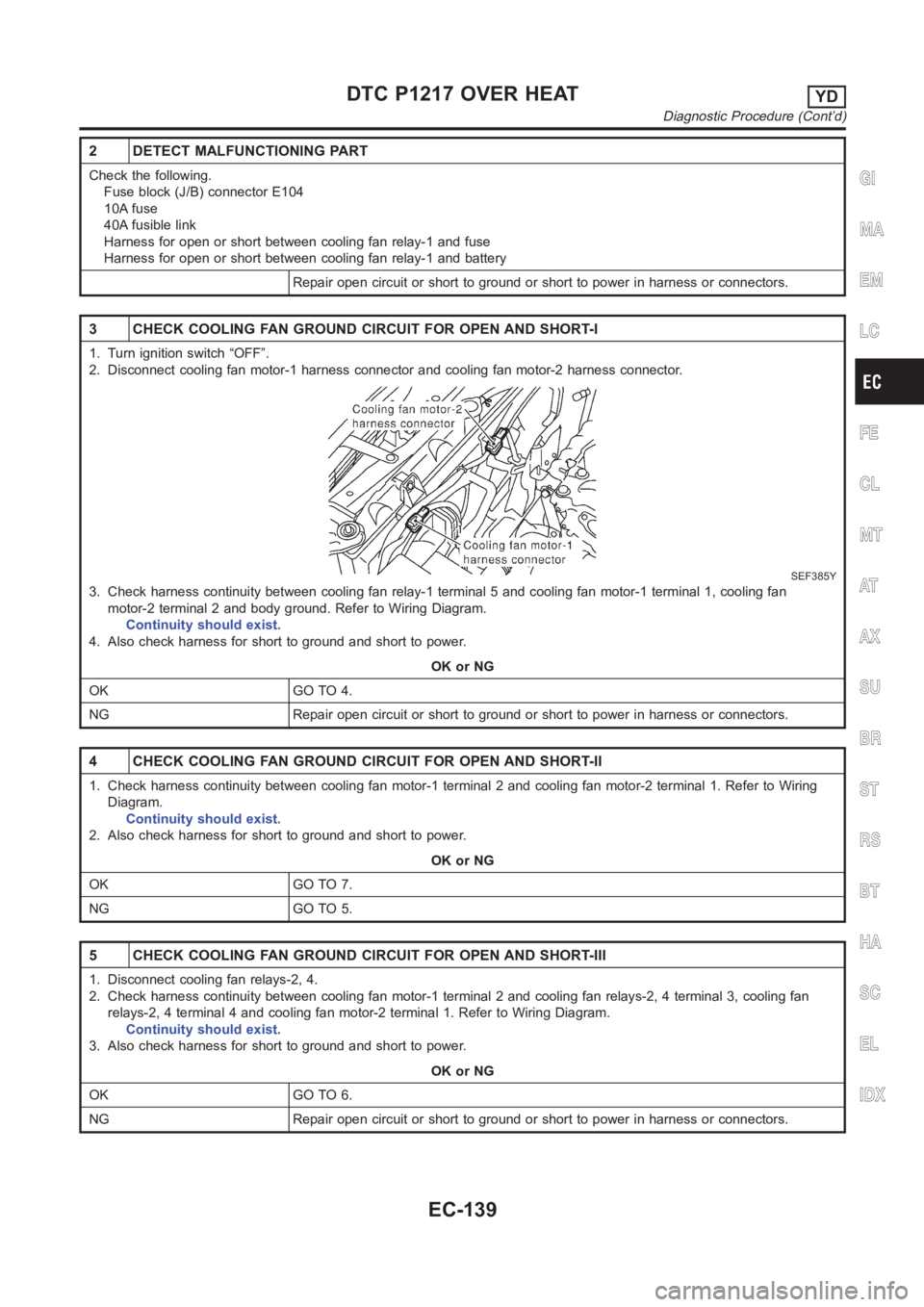
3. Check harness continuity between cooling fan relay-1 terminal 5 and cooling fan motor-1 terminal 1, cooling fan
motor-2 terminal 2 and body ground. Refer to Wiring Diagram.
Continuity should exist.
4. Also check harness for short to ground and short to power.
OK or NG
OK GO TO 4.
NG Repair open circuit or short to ground or short to power in harness or connectors.
4 CHECK COOLING FAN GROUND CIRCUIT FOR OPEN AND SHORT-II
1. Check harness continuity between cooling fan motor-1 terminal 2 and cooling fan motor-2 terminal 1. Refer to Wiring
Diagram.
Continuity should exist.
2. Also check harness for short to ground and short to power.
OK or NG
OK GO TO 7.
NG GO TO 5.
5 CHECK COOLING FAN GROUND CIRCUIT FOR OPEN AND SHORT-III
1. Disconnect cooling fan relays-2, 4.
2. Check harness continuity between cooling fan motor-1 terminal 2 and cooling fan relays-2, 4 terminal 3, cooling fan
relays-2, 4 terminal 4 and cooling fan motor-2 terminal 1. Refer to Wiring Diagram.
Continuity should exist.
3. Also check harness for short to ground and short to power.
OK or NG
OK GO TO 6.
NG Repair open circuit or short to ground or short to power in harness or connectors.
GI
MA
EM
LC
FE
CL
MT
AT
AX
SU
BR
ST
RS
BT
HA
SC
EL
IDX
DTC P1217 OVER HEATYD
Diagnostic Procedure (Cont’d)
EC-139
Page 1260 of 3189

Diagnostic ProcedureNJEC0770
1 CHECK START SIGNAL OVERALL FUNCTION
With CONSULT-II
1. Turn ignition switch “ON”.
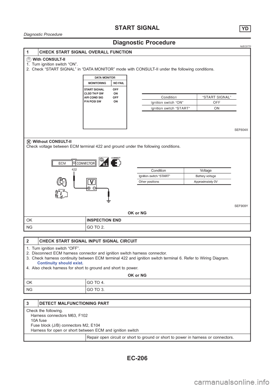
2. Check “START SIGNAL” in “DATA MONITOR” mode with CONSULT-II under the following conditions.
SEF604X
Without CONSULT-II
Check voltage between ECM terminal 422 and ground under the following conditions.
SEF909Y
OK or NG
OKINSPECTION END
NG GO TO 2.
2 CHECK START SIGNAL INPUT SIGNAL CIRCUIT
1. Turn ignition switch “OFF”.
2. Disconnect ECM harness connector and ignition switch harness connector.
3. Check harness continuity between ECM terminal 422 and ignition switch terminal 6. Refer to Wiring Diagram.
Continuity should exist.
4. Also check harness for short to ground and short to power.
OK or NG
OK GO TO 4.
NG GO TO 3.
3 DETECT MALFUNCTIONING PART
Check the following.
Harness connectors M63, F102
10A fuse
Fuse block (J/B) connectors M2, E104
Harness for open or short between ECM and ignition switch
Repair open circuit or short to ground or short to power in harness or connectors.
START SIGNALYD
Diagnostic Procedure
EC-206