2003 NISSAN ALMERA N16 lock
[x] Cancel search: lockPage 6 of 3189
The security indicator is located on the combi meter. The indicator
blinks when the ignition switch is in “OFF” or “ACC” position.
Therefore, NATS warns outsiders that the vehicle is equipped with
the anti-theft system.
When NATS detects trouble, the security indicator lamp lights
up while ignition switch is in “ON” position.
This lighting up indicates that the anti-theft is not functioning,
so prompt service is required.
When servicing NATS (trouble diagnoses, system initialization
and additional registration of other NATS ignition key IDs),
CONSULT-II hardware and CONSULT-II NATS software is
necessary.
Regarding the procedures of NATS initialization and NATS
ignition key ID registration, refer to CONSULT-II operation
manual, NATS.
Therefore, CONSULT-II NATS software (program card and
operation manual) must be kept strictly confidential to main-
tain the integrity of the anti-theft function.
When servicing NATS (trouble diagnoses, system initialization
and additional registration of other NATS ignition key IDs), it
may be necessary to re-register original key identification.
Therefore, be sure to receive all keys from vehicle owner. A
maximum of five key IDs can be registered into NATS.
When failing to start the engine first time using the key of
NATS, start as follows.
a) Leave the ignition key in “ON” position for approximately 5
seconds.
b) Turn ignition key to “OFF” or “LOCK” position and wait approxi-
mately 5 seconds.
c) Repeat step 1 and 2 again.
d) Restart the engine while keeping the key separate from any
others on key-chain.
SGI285
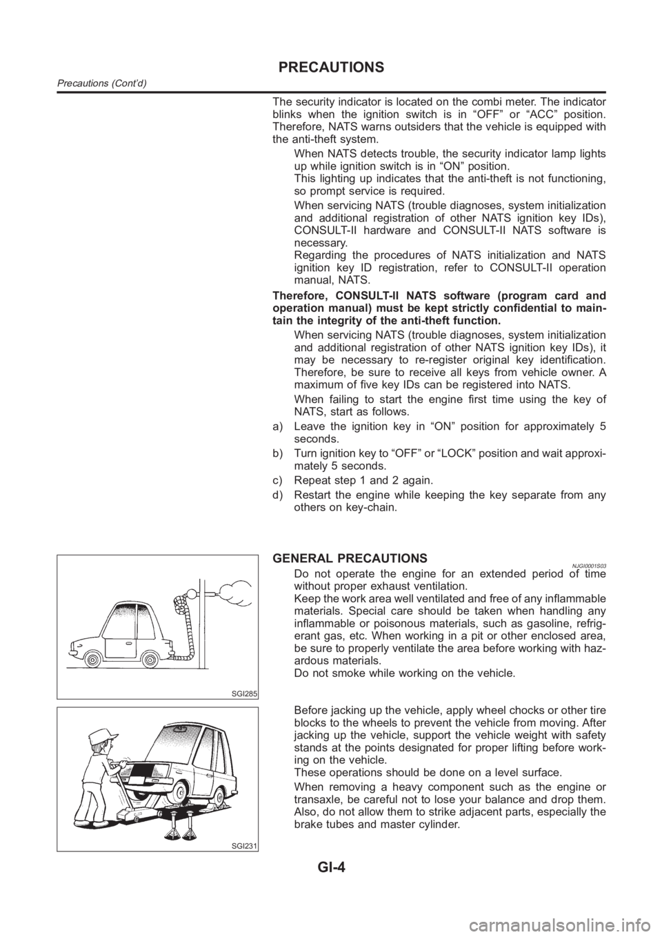
GENERAL PRECAUTIONSNJGI0001S03Do not operate the engine for an extended period of time
without proper exhaust ventilation.
Keep the work area well ventilated and free of any inflammable
materials. Special care should be taken when handling any
inflammable or poisonous materials, such as gasoline, refrig-
erant gas, etc. When working in a pit or other enclosed area,
be sure to properly ventilate the area before working with haz-
ardous materials.
Do not smoke while working on the vehicle.
SGI231
Before jacking up the vehicle, apply wheel chocks or other tire
blocks to the wheels to prevent the vehicle from moving. After
jacking up the vehicle, support the vehicle weight with safety
stands at the points designated for proper lifting before work-
ing on the vehicle.
These operations should be done on a level surface.
When removing a heavy component such as the engine or
transaxle, be careful not to lose your balance and drop them.
Also, do not allow them to strike adjacent parts, especially the
brake tubes and master cylinder.
PRECAUTIONS
Precautions (Cont’d)
GI-4
Page 7 of 3189
SEF289H
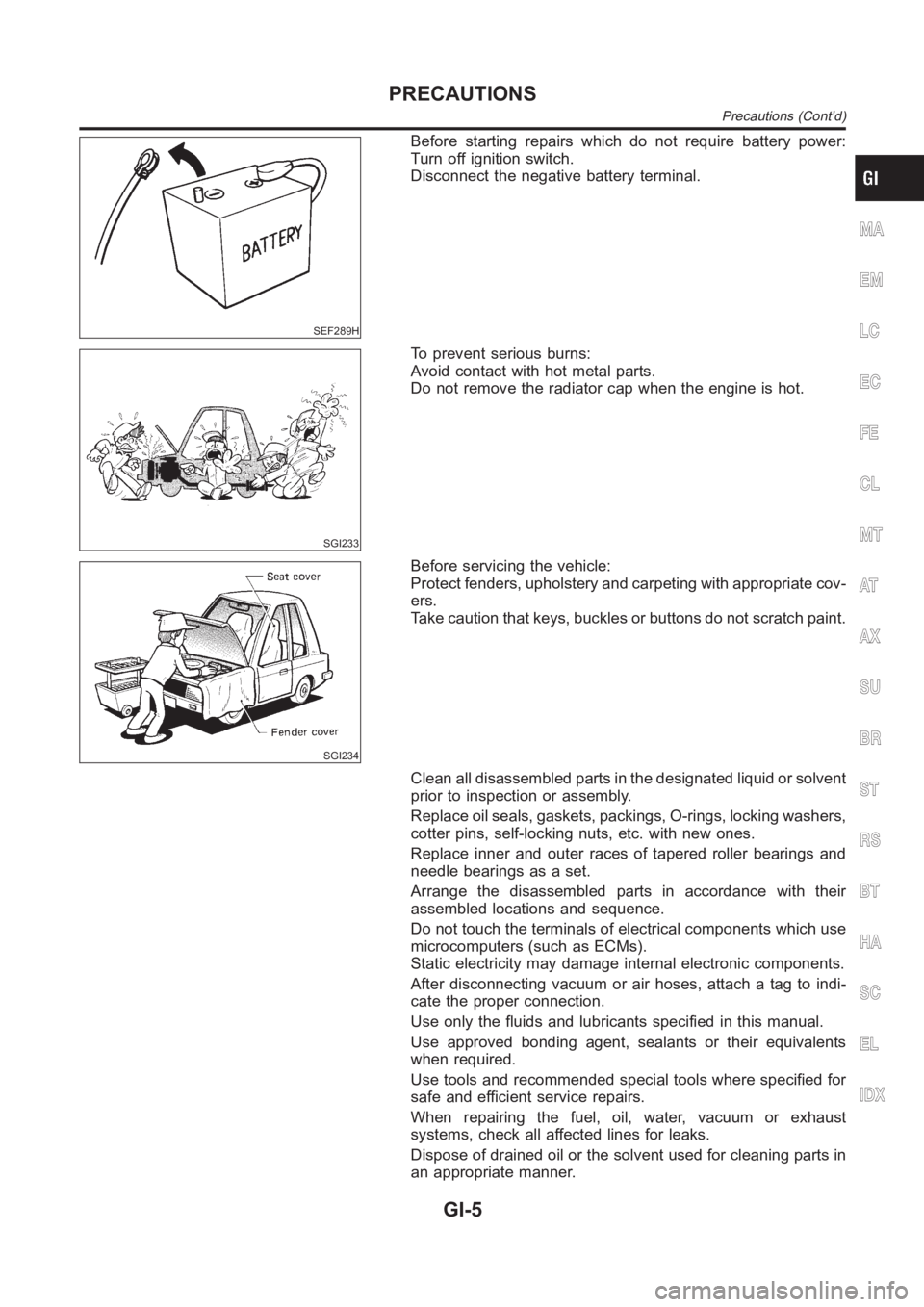
Before starting repairs which do not require battery power:
Turn off ignition switch.
Disconnect the negative battery terminal.
SGI233
To prevent serious burns:
Avoid contact with hot metal parts.
Do not remove the radiator cap when the engine is hot.
SGI234
Before servicing the vehicle:
Protect fenders, upholstery and carpeting with appropriate cov-
ers.
Take caution that keys, buckles or buttons do not scratch paint.
Clean all disassembled parts in the designated liquid or solvent
prior to inspection or assembly.
Replace oil seals, gaskets, packings, O-rings, locking washers,
cotter pins, self-locking nuts, etc. with new ones.
Replace inner and outer races of tapered roller bearings and
needle bearings as a set.
Arrange the disassembled parts in accordance with their
assembled locations and sequence.
Do not touch the terminals of electrical components which use
microcomputers (such as ECMs).
Static electricity may damage internal electronic components.
After disconnecting vacuum or air hoses, attach a tag to indi-
cate the proper connection.
Use only the fluids and lubricants specified in this manual.
Use approved bonding agent, sealants or their equivalents
when required.
Use tools and recommended special tools where specified for
safe and efficient service repairs.
When repairing the fuel, oil, water, vacuum or exhaust
systems, check all affected lines for leaks.
Dispose of drained oil or the solvent used for cleaning parts in
an appropriate manner.
MA
EM
LC
EC
FE
CL
MT
AT
AX
SU
BR
ST
RS
BT
HA
SC
EL
IDX
PRECAUTIONS
Precautions (Cont’d)
GI-5
Page 18 of 3189
SGI364
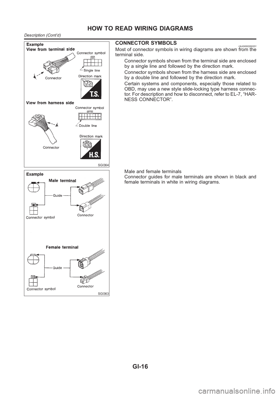
CONNECTOR SYMBOLS=NJGI0003S0201Most of connector symbols in wiring diagrams are shown from the
terminal side.
Connector symbols shown from the terminal side are enclosed
by a single line and followed by the direction mark.
Connector symbols shown from the harness side are enclosed
by a double line and followed by the direction mark.
Certain systems and components, especially those related to
OBD, may use a new style slide-locking type harness connec-
tor. For description and how to disconnect, refer to EL-7, “HAR-
NESS CONNECTOR”.
SGI363
Male and female terminals
Connector guides for male terminals are shown in black and
female terminals in white in wiring diagrams.
HOW TO READ WIRING DIAGRAMS
Description (Cont’d)
GI-16
Page 23 of 3189
manual.
Fuse block — Junction box (J/B)
Fuse block — Junction box (J/B) connector number is shown in the
Reference Area of the wiring diagram. For connector terminal and
fuse arrangement, refer to the “FUSE BLOCK — Junction Box
(J/B)” electrical reference page at the end of the manual.
Fuse and fusible link box
For fuse arrangement in the fuse and fusible link box, refer to the
“FUSE AND FUSIBLE LINK BOX” electrical reference page at the
end of the manual.
Electrical units
Electrical unit connector symbols are shown in the Connector Area
of the wiring diagram.
However, when there is not enough space to show the connector
terminal arrangement in the Connector Area of the wiring diagram,
the electrical unit connector number is shown in the Reference
Area of the wiring diagram. For electrical unit connector terminal
arrangement, refer to the “ELECTRICAL UNITS” electrical refer-
ence page at the end of the manual. Most of the electrical unit
connectors on this page are shown from the harness side of the
connector.
Joint connector
Joint connector symbols are shown in the connector area of the
wiring diagram. For connector internal wiring layout and joint con-
nector terminal arrangement, refer to the “JOINT CONNECTOR
(J/C)” electrical reference page at the end of the manual.
MA
EM
LC
EC
FE
CL
MT
AT
AX
SU
BR
ST
RS
BT
HA
SC
EL
IDX
HOW TO READ WIRING DIAGRAMS
Description (Cont’d)
GI-21
Page 28 of 3189
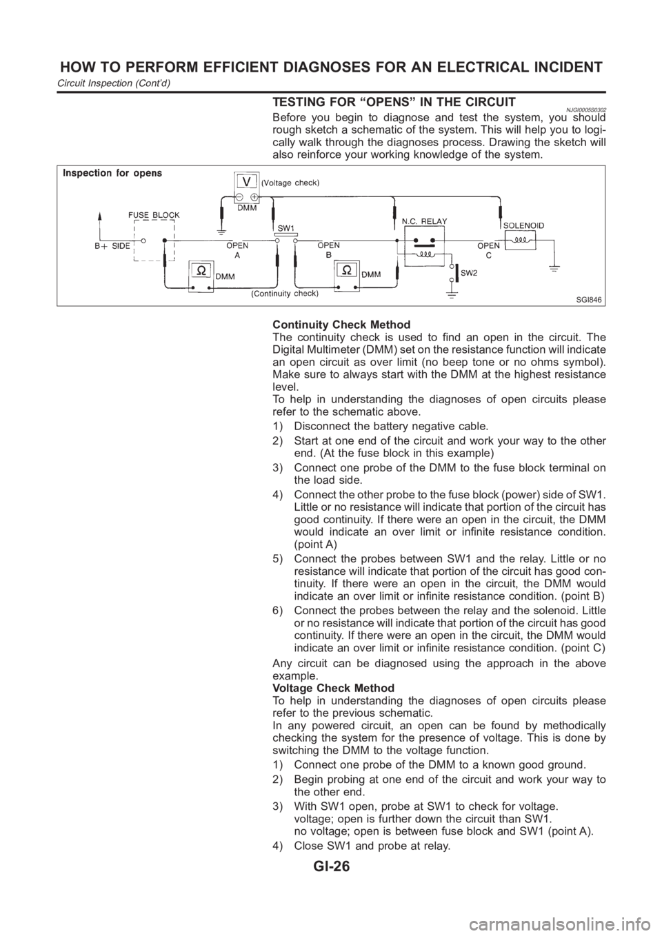
TESTING FOR “OPENS” IN THE CIRCUITNJGI0005S0302Before you begin to diagnose and test the system, you should
rough sketch a schematic of the system. This will help you to logi-
cally walk through the diagnoses process. Drawing the sketch will
also reinforce your working knowledge of the system.
SGI846
Continuity Check Method
The continuity check is used to find an open in the circuit. The
Digital Multimeter (DMM) set on the resistance function will indicate
an open circuit as over limit (no beep tone or no ohms symbol).
Make sure to always start with the DMM at the highest resistance
level.
To help in understanding the diagnoses of open circuits please
refer to the schematic above.
1) Disconnect the battery negative cable.
2) Start at one end of the circuit and work your way to the other
end. (At the fuse block in this example)
3) Connect one probe of the DMM to the fuse block terminal on
the load side.
4) Connect the other probe to the fuse block (power) side of SW1.
Little or no resistance will indicate that portion of the circuit has
good continuity. If there were an open in the circuit, the DMM
would indicate an over limit or infinite resistance condition.
(point A)
5) Connect the probes between SW1 and the relay. Little or no
resistance will indicate that portion of the circuit has good con-
tinuity. If there were an open in the circuit, the DMM would
indicate an over limit or infinite resistance condition. (point B)
6) Connect the probes between the relay and the solenoid. Little
or no resistance will indicate that portion of the circuit has good
continuity. If there were an open in the circuit, the DMM would
indicate an over limit or infinite resistance condition. (point C)
Any circuit can be diagnosed using the approach in the above
example.
Voltage Check Method
To help in understanding the diagnoses of open circuits please
refer to the previous schematic.
In any powered circuit, an open can be found by methodically
checking the system for the presence of voltage. This is done by
switching the DMM to the voltage function.
1) Connect one probe of the DMM to a known good ground.
2) Begin probing at one end of the circuit and work your way to
the other end.
3) With SW1 open, probe at SW1 to check for voltage.
voltage; open is further down the circuit than SW1.
no voltage; open is between fuse block and SW1 (point A).
4) Close SW1 and probe at relay.
HOW TO PERFORM EFFICIENT DIAGNOSES FOR AN ELECTRICAL INCIDENT
Circuit Inspection (Cont’d)
GI-26
Page 29 of 3189
voltage; open is further down the circuit than the relay.
no voltage; open is between SW1 and relay (point B).
5) Close the relay and probe at the solenoid.
voltage; open is further down the circuit than the solenoid.
no voltage; open is between relay and solenoid (point C).
Any powered circuit can be diagnosed using the approach in the
above example.
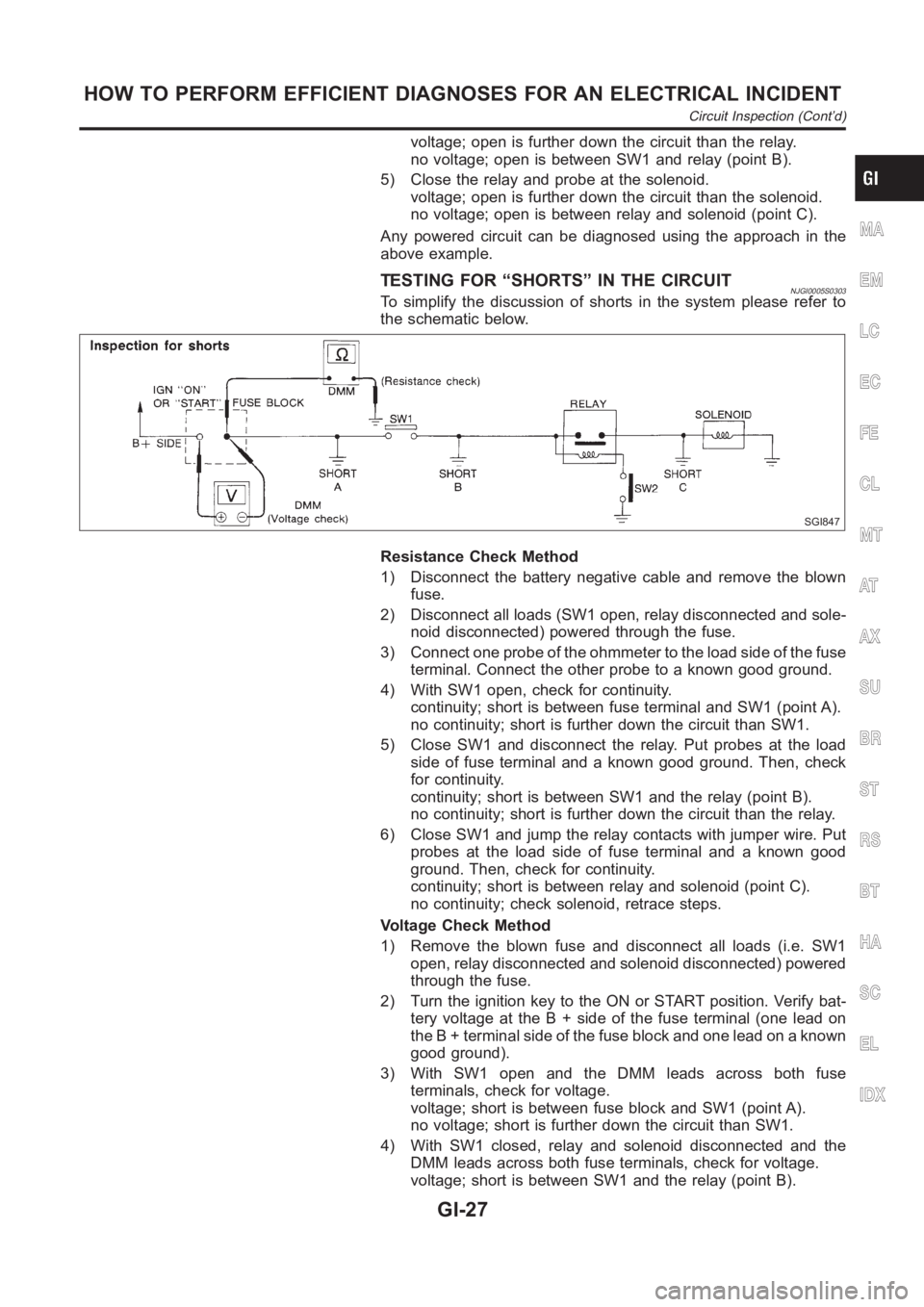
TESTING FOR “SHORTS” IN THE CIRCUITNJGI0005S0303To simplify the discussion of shorts in the system please refer to
the schematic below.
SGI847
Resistance Check Method
1) Disconnect the battery negative cable and remove the blown
fuse.
2) Disconnect all loads (SW1 open, relay disconnected and sole-
noid disconnected) powered through the fuse.
3) Connect one probe of the ohmmeter to the load side of the fuse
terminal. Connect the other probe to a known good ground.
4) With SW1 open, check for continuity.
continuity; short is between fuse terminal and SW1 (point A).
no continuity; short is further down the circuit than SW1.
5) Close SW1 and disconnect the relay. Put probes at the load
side of fuse terminal and a known good ground. Then, check
for continuity.
continuity; short is between SW1 and the relay (point B).
no continuity; short is further down the circuit than the relay.
6) Close SW1 and jump the relay contacts with jumper wire. Put
probes at the load side of fuse terminal and a known good
ground. Then, check for continuity.
continuity; short is between relay and solenoid (point C).
no continuity; check solenoid, retrace steps.
Voltage Check Method
1) Remove the blown fuse and disconnect all loads (i.e. SW1
open, relay disconnected and solenoid disconnected) powered
through the fuse.
2) Turn the ignition key to the ON or START position. Verify bat-
tery voltage at the B + side of the fuse terminal (one lead on
the B + terminal side of the fuse block and one lead on a known
good ground).
3) With SW1 open and the DMM leads across both fuse
terminals, check for voltage.
voltage; short is between fuse block and SW1 (point A).
no voltage; short is further down the circuit than SW1.
4) With SW1 closed, relay and solenoid disconnected and the
DMM leads across both fuse terminals, check for voltage.
voltage; short is between SW1 and the relay (point B).
MA
EM
LC
EC
FE
CL
MT
AT
AX
SU
BR
ST
RS
BT
HA
SC
EL
IDX
HOW TO PERFORM EFFICIENT DIAGNOSES FOR AN ELECTRICAL INCIDENT
Circuit Inspection (Cont’d)
GI-27
Page 30 of 3189
no voltage; short is further down the circuit than the relay.
5) With SW1 closed, relay contacts jumped with fused jumper
wire check for voltage.
voltage; short is down the circuit of the relay or between the
relay and the disconnected solenoid (point C).
no voltage; retrace steps and check power to fuse block.
GROUND INSPECTIONNJGI0005S0304Ground connections are very important to the proper operation of
electrical and electronic circuits. Ground connections are often
exposed to moisture, dirt and other corrosive elements. The corro-
sion (rust) can become an unwanted resistance. This unwanted
resistance can change the way a circuit works.
Electronically controlled circuits are very sensitive to proper
grounding. A loose or corroded ground can drastically affect an
electronically controlled circuit. A poor or corroded ground can eas-
ily affect the circuit. Even when the ground connection looks clean,
there can be a thin film of rust on the surface.
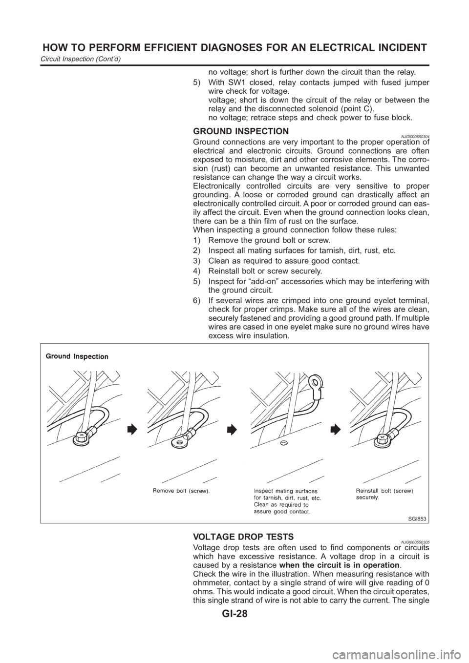
When inspecting a ground connection follow these rules:
1) Remove the ground bolt or screw.
2) Inspect all mating surfaces for tarnish, dirt, rust, etc.
3) Clean as required to assure good contact.
4) Reinstall bolt or screw securely.
5) Inspect for “add-on” accessories which may be interfering with
the ground circuit.
6) If several wires are crimped into one ground eyelet terminal,
check for proper crimps. Make sure all of the wires are clean,
securely fastened and providing a good ground path. If multiple
wires are cased in one eyelet make sure no ground wires have
excess wire insulation.
SGI853
VOLTAGE DROP TESTSNJGI0005S0305Voltage drop tests are often used to find components or circuits
which have excessive resistance. A voltage drop in a circuit is
caused by a resistancewhen the circuit is in operation.
Check the wire in the illustration. When measuring resistance with
ohmmeter, contact by a single strand of wire will give reading of 0
ohms. This would indicate a good circuit. When the circuit operates,
this single strand of wire is not able to carry the current. The single
HOW TO PERFORM EFFICIENT DIAGNOSES FOR AN ELECTRICAL INCIDENT
Circuit Inspection (Cont’d)
GI-28
Page 38 of 3189
NJGI0007
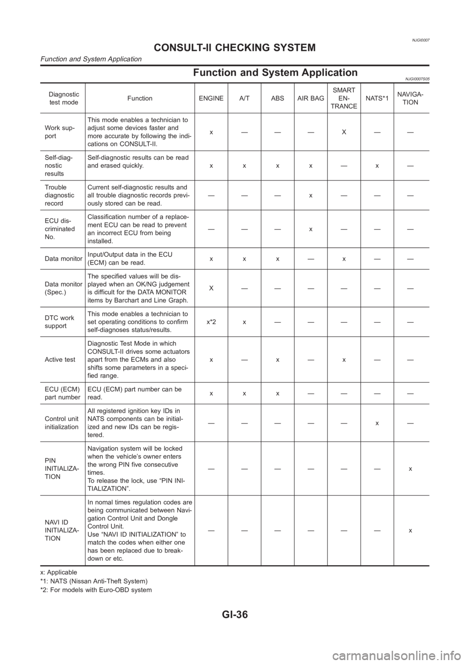
Function and System ApplicationNJGI0007S05
Diagnostic
test modeFunction ENGINE A/T ABS AIR BAGSMART
EN-
TRANCENATS*1NAVIGA-
TION
Work sup-
portThis mode enables a technician to
adjust some devices faster and
more accurate by following the indi-
cations on CONSULT-II.x ———X——
Self-diag-
nostic
resultsSelf-diagnostic results can be read
anderasedquickly. x x x x—x—
Trouble
diagnostic
recordCurrent self-diagnostic results and
all trouble diagnostic records previ-
ously stored can be read.——— x ———
ECU dis-
criminated
No.Classification number of a replace-
ment ECU can be read to prevent
an incorrect ECU from being
installed.——— x ———
Data monitorInput/Output data in the ECU
(ECM) can be read.x x x—x——
Data monitor
(Spec.)The specified values will be dis-
played when an OK/NG judgement
is difficult for the DATA MONITOR
items by Barchart and Line Graph.X ——————
DTC work
supportThis mode enables a technician to
set operating conditions to confirm
self-diagnoses status/results.x*2x —————
Active testDiagnostic Test Mode in which
CONSULT-II drives some actuators
apart from the ECMs and also
shifts some parameters in a speci-
fied range.x—x—x——
ECU (ECM)
part numberECU (ECM) part number can be
read.x x x ————
Control unit
initializationAll registered ignition key IDs in
NATS components can be initial-
ized and new IDs can be regis-
tered.————— x —
PIN
INITIALIZA-
TIONNavigation system will be locked
when the vehicle’s owner enters
the wrong PIN five consecutive
times.
To release the lock, use “PIN INI-
TIALIZATION”.—————— x
NAVI ID
INITIALIZA-
TIONIn nomal times regulation codes are
being communicated between Navi-
gation Control Unit and Dongle
Control Unit.
Use “NAVI ID INITIALIZATION” to
match the codes when either one
has been replaced due to break-
down or etc.—————— x
x: Applicable
*1: NATS (Nissan Anti-Theft System)
*2: For models with Euro-OBD system
CONSULT-II CHECKING SYSTEM
Function and System Application
GI-36