2003 NISSAN ALMERA N16 ECU
[x] Cancel search: ECUPage 6 of 3189
The security indicator is located on the combi meter. The indicator
blinks when the ignition switch is in “OFF” or “ACC” position.
Therefore, NATS warns outsiders that the vehicle is equipped with
the anti-theft system.
When NATS detects trouble, the security indicator lamp lights
up while ignition switch is in “ON” position.
This lighting up indicates that the anti-theft is not functioning,
so prompt service is required.
When servicing NATS (trouble diagnoses, system initialization
and additional registration of other NATS ignition key IDs),
CONSULT-II hardware and CONSULT-II NATS software is
necessary.
Regarding the procedures of NATS initialization and NATS
ignition key ID registration, refer to CONSULT-II operation
manual, NATS.
Therefore, CONSULT-II NATS software (program card and
operation manual) must be kept strictly confidential to main-
tain the integrity of the anti-theft function.
When servicing NATS (trouble diagnoses, system initialization
and additional registration of other NATS ignition key IDs), it
may be necessary to re-register original key identification.
Therefore, be sure to receive all keys from vehicle owner. A
maximum of five key IDs can be registered into NATS.
When failing to start the engine first time using the key of
NATS, start as follows.
a) Leave the ignition key in “ON” position for approximately 5
seconds.
b) Turn ignition key to “OFF” or “LOCK” position and wait approxi-
mately 5 seconds.
c) Repeat step 1 and 2 again.
d) Restart the engine while keeping the key separate from any
others on key-chain.
SGI285
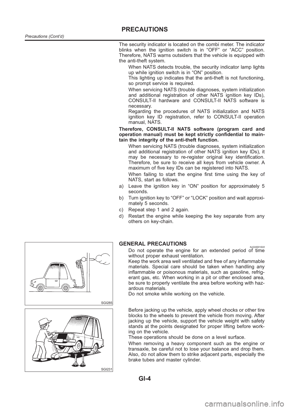
GENERAL PRECAUTIONSNJGI0001S03Do not operate the engine for an extended period of time
without proper exhaust ventilation.
Keep the work area well ventilated and free of any inflammable
materials. Special care should be taken when handling any
inflammable or poisonous materials, such as gasoline, refrig-
erant gas, etc. When working in a pit or other enclosed area,
be sure to properly ventilate the area before working with haz-
ardous materials.
Do not smoke while working on the vehicle.
SGI231
Before jacking up the vehicle, apply wheel chocks or other tire
blocks to the wheels to prevent the vehicle from moving. After
jacking up the vehicle, support the vehicle weight with safety
stands at the points designated for proper lifting before work-
ing on the vehicle.
These operations should be done on a level surface.
When removing a heavy component such as the engine or
transaxle, be careful not to lose your balance and drop them.
Also, do not allow them to strike adjacent parts, especially the
brake tubes and master cylinder.
PRECAUTIONS
Precautions (Cont’d)
GI-4
Page 9 of 3189
SMA020D
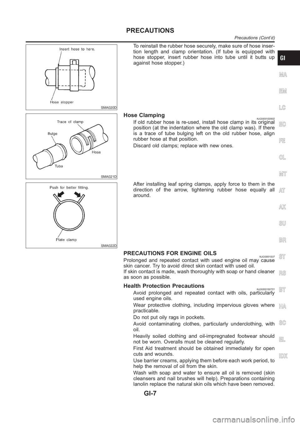
To reinstall the rubber hose securely, make sure of hose inser-
tion length and clamp orientation. (If tube is equipped with
hose stopper, insert rubber hose into tube until it butts up
against hose stopper.)
SMA021D
Hose ClampingNJGI0001S0602If old rubber hose is re-used, install hose clamp in its original
position (at the indentation where the old clamp was). If there
is a trace of tube bulging left on the old rubber hose, align
rubber hose at that position.
Discard old clamps; replace with new ones.
SMA022D
After installing leaf spring clamps, apply force to them in the
direction of the arrow, tightening rubber hose equally all
around.
PRECAUTIONS FOR ENGINE OILSNJGI0001S07Prolonged and repeated contact with used engine oil may cause
skin cancer. Try to avoid direct skin contact with used oil.
If skin contact is made, wash thoroughly with soap or hand cleaner
as soon as possible.
Health Protection PrecautionsNJGI0001S0701Avoid prolonged and repeated contact with oils, particularly
used engine oils.
Wear protective clothing, including impervious gloves where
practicable.
Do not put oily rags in pockets.
Avoid contaminating clothes, particularly underclothing, with
oil.
Heavily soiled clothing and oil-impregnated footwear should
not be worn. Overalls must be cleaned regularly.
First Aid treatment should be obtained immediately for open
cuts and wounds.
Use barrier creams, applying them before each work period, to
help the removal of oil from the skin.
Wash with soap and water to ensure all oil is removed (skin
cleansers and nail brushes will help). Preparations containing
lanolin replace the natural skin oils which have been removed.
MA
EM
LC
EC
FE
CL
MT
AT
AX
SU
BR
ST
RS
BT
HA
SC
EL
IDX
PRECAUTIONS
Precautions (Cont’d)
GI-7
Page 30 of 3189
no voltage; short is further down the circuit than the relay.
5) With SW1 closed, relay contacts jumped with fused jumper
wire check for voltage.
voltage; short is down the circuit of the relay or between the
relay and the disconnected solenoid (point C).
no voltage; retrace steps and check power to fuse block.
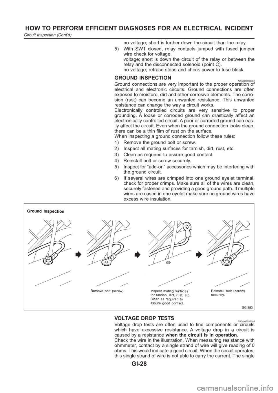
GROUND INSPECTIONNJGI0005S0304Ground connections are very important to the proper operation of
electrical and electronic circuits. Ground connections are often
exposed to moisture, dirt and other corrosive elements. The corro-
sion (rust) can become an unwanted resistance. This unwanted
resistance can change the way a circuit works.
Electronically controlled circuits are very sensitive to proper
grounding. A loose or corroded ground can drastically affect an
electronically controlled circuit. A poor or corroded ground can eas-
ily affect the circuit. Even when the ground connection looks clean,
there can be a thin film of rust on the surface.
When inspecting a ground connection follow these rules:
1) Remove the ground bolt or screw.
2) Inspect all mating surfaces for tarnish, dirt, rust, etc.
3) Clean as required to assure good contact.
4) Reinstall bolt or screw securely.
5) Inspect for “add-on” accessories which may be interfering with
the ground circuit.
6) If several wires are crimped into one ground eyelet terminal,
check for proper crimps. Make sure all of the wires are clean,
securely fastened and providing a good ground path. If multiple
wires are cased in one eyelet make sure no ground wires have
excess wire insulation.
SGI853
VOLTAGE DROP TESTSNJGI0005S0305Voltage drop tests are often used to find components or circuits
which have excessive resistance. A voltage drop in a circuit is
caused by a resistancewhen the circuit is in operation.
Check the wire in the illustration. When measuring resistance with
ohmmeter, contact by a single strand of wire will give reading of 0
ohms. This would indicate a good circuit. When the circuit operates,
this single strand of wire is not able to carry the current. The single
HOW TO PERFORM EFFICIENT DIAGNOSES FOR AN ELECTRICAL INCIDENT
Circuit Inspection (Cont’d)
GI-28
Page 38 of 3189
NJGI0007
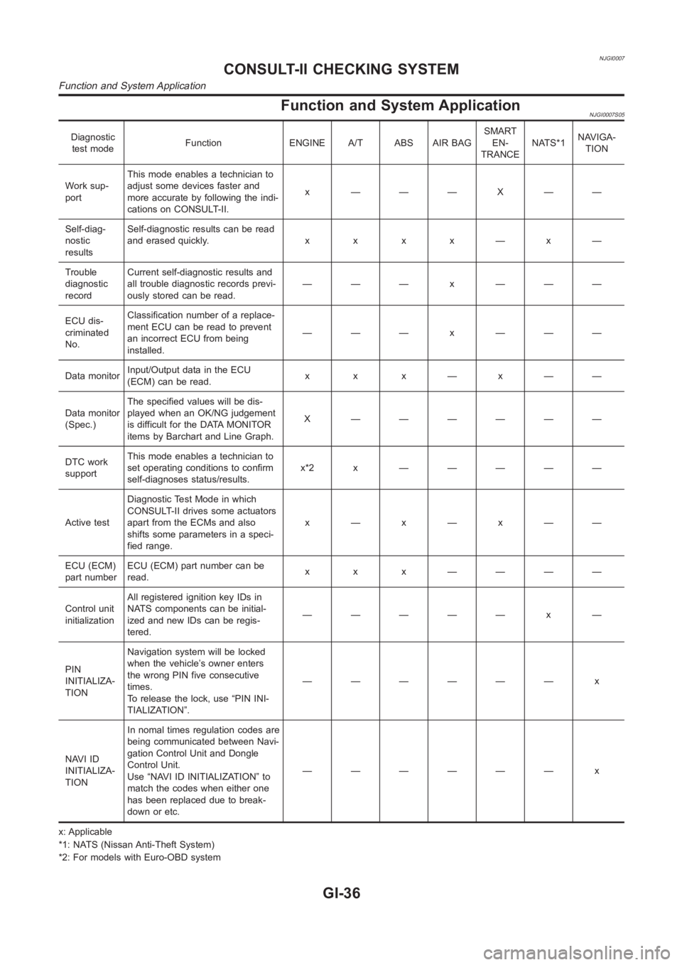
Function and System ApplicationNJGI0007S05
Diagnostic
test modeFunction ENGINE A/T ABS AIR BAGSMART
EN-
TRANCENATS*1NAVIGA-
TION
Work sup-
portThis mode enables a technician to
adjust some devices faster and
more accurate by following the indi-
cations on CONSULT-II.x ———X——
Self-diag-
nostic
resultsSelf-diagnostic results can be read
anderasedquickly. x x x x—x—
Trouble
diagnostic
recordCurrent self-diagnostic results and
all trouble diagnostic records previ-
ously stored can be read.——— x ———
ECU dis-
criminated
No.Classification number of a replace-
ment ECU can be read to prevent
an incorrect ECU from being
installed.——— x ———
Data monitorInput/Output data in the ECU
(ECM) can be read.x x x—x——
Data monitor
(Spec.)The specified values will be dis-
played when an OK/NG judgement
is difficult for the DATA MONITOR
items by Barchart and Line Graph.X ——————
DTC work
supportThis mode enables a technician to
set operating conditions to confirm
self-diagnoses status/results.x*2x —————
Active testDiagnostic Test Mode in which
CONSULT-II drives some actuators
apart from the ECMs and also
shifts some parameters in a speci-
fied range.x—x—x——
ECU (ECM)
part numberECU (ECM) part number can be
read.x x x ————
Control unit
initializationAll registered ignition key IDs in
NATS components can be initial-
ized and new IDs can be regis-
tered.————— x —
PIN
INITIALIZA-
TIONNavigation system will be locked
when the vehicle’s owner enters
the wrong PIN five consecutive
times.
To release the lock, use “PIN INI-
TIALIZATION”.—————— x
NAVI ID
INITIALIZA-
TIONIn nomal times regulation codes are
being communicated between Navi-
gation Control Unit and Dongle
Control Unit.
Use “NAVI ID INITIALIZATION” to
match the codes when either one
has been replaced due to break-
down or etc.—————— x
x: Applicable
*1: NATS (Nissan Anti-Theft System)
*2: For models with Euro-OBD system
CONSULT-II CHECKING SYSTEM
Function and System Application
GI-36
Page 59 of 3189
NJMA0004
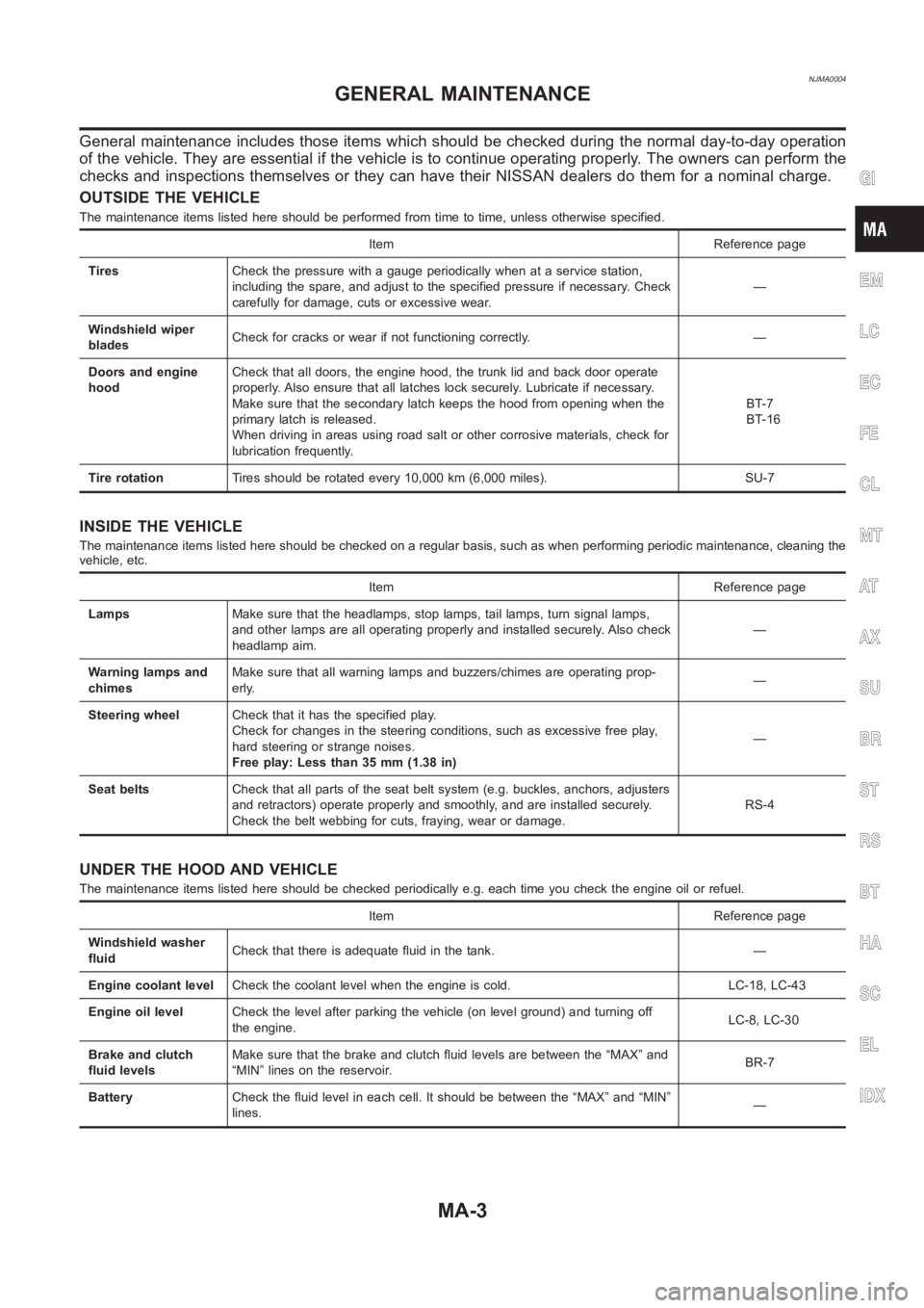
General maintenance includes those items which should be checked during the normal day-to-day operation
of the vehicle. They are essential if the vehicle is to continue operating properly. The owners can perform the
checks and inspections themselves or they can have their NISSAN dealers dothem for a nominal charge.
OUTSIDE THE VEHICLE
The maintenance items listed here should be performed from time to time, unless otherwise specified.
Item Reference page
TiresCheck the pressure with a gauge periodically when at a service station,
including the spare, and adjust to the specified pressure if necessary. Check
carefully for damage, cuts or excessive wear.—
Windshield wiper
bladesCheck for cracks or wear if not functioning correctly. —
Doors and engine
hoodCheck that all doors, the engine hood, the trunk lid and back door operate
properly. Also ensure that all latches lock securely. Lubricate if necessary.
Make sure that the secondary latch keeps the hood from opening when the
primary latch is released.
When driving in areas using road salt or other corrosive materials, check for
lubrication frequently.BT-7
BT-16
Tire rotationTires should be rotated every 10,000 km (6,000 miles). SU-7
INSIDE THE VEHICLE
The maintenance items listed here should be checked on a regular basis, such as when performing periodic maintenance, cleaning the
vehicle, etc.
Item Reference page
LampsMake sure that the headlamps, stop lamps, tail lamps, turn signal lamps,
and other lamps are all operating properly and installed securely. Also check
headlamp aim.—
Warning lamps and
chimesMake sure that all warning lamps and buzzers/chimes are operating prop-
erly.—
Steering wheelCheck that it has the specified play.
Check for changes in the steering conditions, such as excessive free play,
hard steering or strange noises.
Free play: Less than 35 mm (1.38 in)—
Seat beltsCheck that all parts of the seat belt system (e.g. buckles, anchors, adjusters
and retractors) operate properly and smoothly, and are installed securely.
Check the belt webbing for cuts, fraying, wear or damage.RS-4
UNDER THE HOOD AND VEHICLE
The maintenance items listed here should be checked periodically e.g. each time you check the engine oil or refuel.
Item Reference page
Windshield washer
fluidCheck that there is adequate fluid in the tank. —
Engine coolant levelCheck the coolant level when the engine is cold. LC-18, LC-43
Engine oil levelCheck the level after parking the vehicle (on level ground) and turning off
the engine.LC-8, LC-30
Brake and clutch
fluid levelsMake sure that the brake and clutch fluid levels are between the “MAX” and
“MIN” lines on the reservoir.BR-7
BatteryCheck the fluid level in each cell. It should be between the “MAX” and “MIN”
lines.—
GI
EM
LC
EC
FE
CL
MT
AT
AX
SU
BR
ST
RS
BT
HA
SC
EL
IDX
GENERAL MAINTENANCE
MA-3
Page 105 of 3189
![NISSAN ALMERA N16 2003 Electronic Repair Manual FUEL INJECTOR AND FUEL TUBE
EM-27
[QG]
C
D
E
F
G
H
I
J
K
L
MA
EM
CAUTION:
Do not touch fuel injector nozzle with intake manifold or other parts.
5. Remove fuel injector from fuel tube.
●Release clip NISSAN ALMERA N16 2003 Electronic Repair Manual FUEL INJECTOR AND FUEL TUBE
EM-27
[QG]
C
D
E
F
G
H
I
J
K
L
MA
EM
CAUTION:
Do not touch fuel injector nozzle with intake manifold or other parts.
5. Remove fuel injector from fuel tube.
●Release clip](/manual-img/5/57350/w960_57350-104.png)
FUEL INJECTOR AND FUEL TUBE
EM-27
[QG]
C
D
E
F
G
H
I
J
K
L
MA
EM
CAUTION:
Do not touch fuel injector nozzle with intake manifold or other parts.
5. Remove fuel injector from fuel tube.
●Release clip and remove it.
●Pull fuel injector straight out of fuel tube.
CAUTION:
●Be careful not to damage nozzle part.
●Avoid any impact such as a dropping.
●Do not disassemble or adjust it.
INSTALLATION
1. When installing O-ring to fuel injector, follow instructions described below.
CAUTION:
●Handle O-ring with bare hands. Never wear gloves.
●Lubricate O-ring with new engine oil.
●Do not clean O-ring with solvent.
●Make sure that O-ring and its mating part are free of foreign material.
●Be careful not to scratch it with a tool or fingernails during installation. Also be careful not to
twist or stretch O-ring. If O-ring is stretched while being attached, do not insert it into fuel tube
immediately.
●Insert O-ring straight into fuel tube. Do not angle or twist it.
2.
Install fuel injector to fuel tube with the following procedure.
a. Insert clip into clip mounting groove on fuel injector.
●Insert clip so that lug “A” of fuel injector matches notch “A” of
the clip.
CAUTION:
●Do not reuse clip. Replace it with a new one.
●Be careful to keep clip from interfering with O-ring. If
interference occurs, replace O-ring.
b. Insert fuel injector into fuel tube with clip attached.
●Insert it while matching it to the axial center.
●Insert fuel injector so that lug “B” of fuel tube matches notch
“B” of the clip.
●Make sure that fuel tube flange is securely fixed in flange fix-
ing groove on clip.
c. Make sure that installation is complete by checking that fuel
injector does not rotate or come off.
PBIC0620E
PBIC1021E
Page 106 of 3189
![NISSAN ALMERA N16 2003 Electronic Repair Manual EM-28
[QG]
FUEL INJECTOR AND FUEL TUBE
3. Tighten mounting bolts in two steps in numerical order shown in
figure.
4. Install fuel feed hose.
CAUTION:
Install hose clamp avoiding interference with NISSAN ALMERA N16 2003 Electronic Repair Manual EM-28
[QG]
FUEL INJECTOR AND FUEL TUBE
3. Tighten mounting bolts in two steps in numerical order shown in
figure.
4. Install fuel feed hose.
CAUTION:
Install hose clamp avoiding interference with](/manual-img/5/57350/w960_57350-105.png)
EM-28
[QG]
FUEL INJECTOR AND FUEL TUBE
3. Tighten mounting bolts in two steps in numerical order shown in
figure.
4. Install fuel feed hose.
CAUTION:
Install hose clamp avoiding interference with bulge, and
securely tighten it
5. Install remaining parts in the reverse order of removal.
INSPECTION AFTER INSTALLATION
●Check for fuel leakage with following procedure.
1. Turn ignition switch ON (do not start engine), and check connections for leakage by applying fuel pressure
to fuel piping.
2. Start engine, and re-check connections for fuel leakage by increasing engine speed. 1st step : 11.8 - 13.8 N·m (1.2 - 1.4 kg-m, 9 - 10 ft-lb)
2nd step : 17 - 23 N·m (1.7 - 2.4 kg-m, 13 - 17 ft-lb)
PBIC0617E
Page 110 of 3189
![NISSAN ALMERA N16 2003 Electronic Repair Manual EM-32
[QG]
CAMSHAFT
CAMSHAFT
PFP:13001
Removal and InstallationEBS00LQB
CAUTION:
Prior to installation, apply engine oil to the parts marked in the figure.
REMOVAL
1. Remove rocker cover. Refer to EM- NISSAN ALMERA N16 2003 Electronic Repair Manual EM-32
[QG]
CAMSHAFT
CAMSHAFT
PFP:13001
Removal and InstallationEBS00LQB
CAUTION:
Prior to installation, apply engine oil to the parts marked in the figure.
REMOVAL
1. Remove rocker cover. Refer to EM-](/manual-img/5/57350/w960_57350-109.png)
EM-32
[QG]
CAMSHAFT
CAMSHAFT
PFP:13001
Removal and InstallationEBS00LQB
CAUTION:
Prior to installation, apply engine oil to the parts marked in the figure.
REMOVAL
1. Remove rocker cover. Refer to EM-29, "ROCKER COVER" .
2. Remove cylinder head front cover.
●Move harness secured to front surface beforehand.
3. Set No. 1 cylinder at TDC of its compression stroke.
a. Remove RH splash cover (integrated with undercover).
b. Rotate crankshaft pulley clockwise and align yellow paint mark
with timing indicator.
PBIC0965E
1. Camshaft bracket 2. Camshaft sprocket (INT) 3. Camshaft sprocket (EXH)
4. Washer 5. Cylinder head front cover 6. Chain tensioner
7. Valve lifter 8. Adjusting shim (If so equipped) 9. Camshaft (EXH)
10. Camshaft (INT)
MBIB0193E