Page 55 of 3189

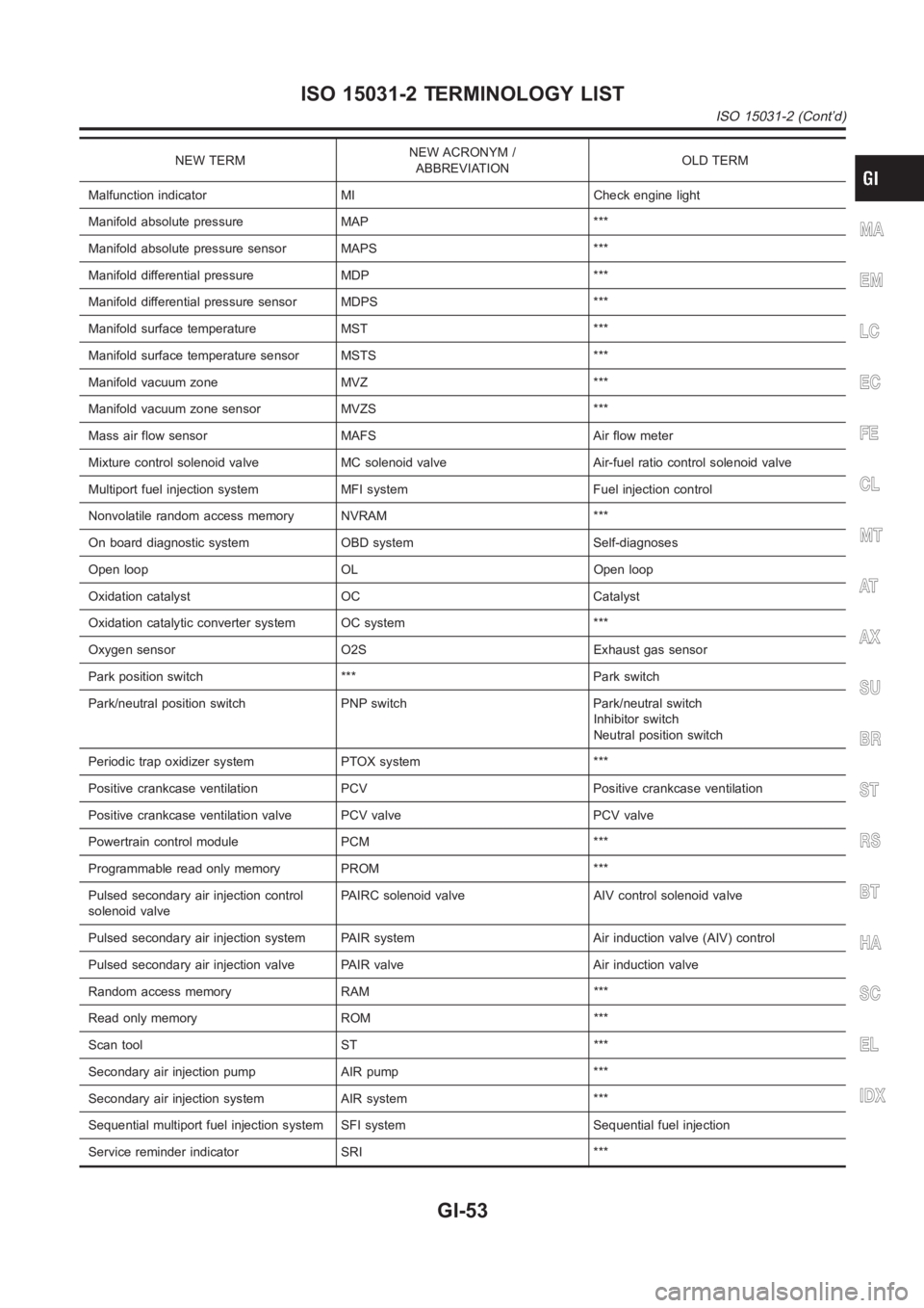
NEW TERMNEW ACRONYM /
ABBREVIATIONOLD TERM
Malfunction indicator MI Check engine light
Manifold absolute pressure MAP ***
Manifold absolute pressure sensor MAPS ***
Manifold differential pressure MDP ***
Manifold differential pressure sensor MDPS ***
Manifold surface temperature MST ***
Manifold surface temperature sensor MSTS ***
Manifold vacuum zone MVZ ***
Manifold vacuum zone sensor MVZS ***
Mass air flow sensor MAFS Air flow meter
Mixture control solenoid valve MC solenoid valve Air-fuel ratio control solenoid valve
Multiport fuel injection system MFI system Fuel injection control
Nonvolatile random access memory NVRAM ***
On board diagnostic system OBD system Self-diagnoses
Open loop OL Open loop
Oxidation catalyst OC Catalyst
Oxidation catalytic converter system OC system ***
Oxygen sensor O2S Exhaust gas sensor
Park position switch *** Park switch
Park/neutral position switch PNP switch Park/neutral switch
Inhibitor switch
Neutral position switch
Periodic trap oxidizer system PTOX system ***
Positive crankcase ventilation PCV Positive crankcase ventilation
Positive crankcase ventilation valve PCV valve PCV valve
Powertrain control module PCM ***
Programmable read only memory PROM ***
Pulsed secondary air injection control
solenoid valvePAIRC solenoid valve AIV control solenoid valve
Pulsed secondary air injection system PAIR system Air induction valve (AIV) control
Pulsed secondary air injection valve PAIR valve Air induction valve
Random access memory RAM ***
Read only memory ROM ***
Scan tool ST ***
Secondary air injection pump AIR pump ***
Secondary air injection system AIR system ***
Sequential multiport fuel injection system SFI system Sequential fuel injection
Service reminder indicator SRI ***
MA
EM
LC
EC
FE
CL
MT
AT
AX
SU
BR
ST
RS
BT
HA
SC
EL
IDX
ISO 15031-2 TERMINOLOGY LIST
ISO 15031-2 (Cont’d)
GI-53
Page 56 of 3189

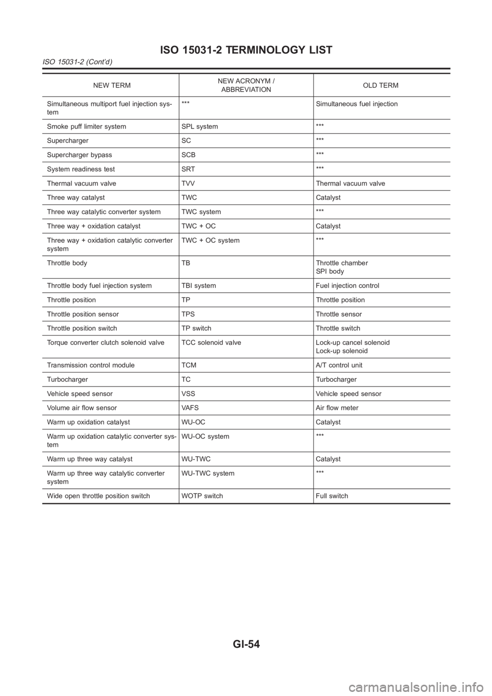
NEW TERMNEW ACRONYM /
ABBREVIATIONOLD TERM
Simultaneous multiport fuel injection sys-
tem*** Simultaneous fuel injection
Smoke puff limiter system SPL system ***
Supercharger SC ***
Supercharger bypass SCB ***
System readiness test SRT ***
Thermal vacuum valve TVV Thermal vacuum valve
Three way catalyst TWC Catalyst
Three way catalytic converter system TWC system ***
Three way + oxidation catalyst TWC + OC Catalyst
Three way + oxidation catalytic converter
systemTWC + OC system ***
Throttle body TB Throttle chamber
SPI body
Throttle body fuel injection system TBI system Fuel injection control
Throttle position TP Throttle position
Throttle position sensor TPS Throttle sensor
Throttle position switch TP switch Throttle switch
Torque converter clutch solenoid valve TCC solenoid valve Lock-up cancelsolenoid
Lock-up solenoid
Transmission control module TCM A/T control unit
Turbocharger TC Turbocharger
Vehicle speed sensor VSS Vehicle speed sensor
Volume air flow sensor VAFS Air flow meter
Warm up oxidation catalyst WU-OC Catalyst
Warm up oxidation catalytic converter sys-
temWU-OC system ***
Warm up three way catalyst WU-TWC Catalyst
Warm up three way catalytic converter
systemWU-TWC system ***
Wide open throttle position switch WOTP switch Full switch
ISO 15031-2 TERMINOLOGY LIST
ISO 15031-2 (Cont’d)
GI-54
Page 97 of 3189
EXHAUST MANIFOLD AND CATALYTIC CONVERTER
EM-19
[QG]
C
D
E
F
G
H
I
J
K
L
MA
EM
EXHAUST MANIFOLD AND CATALYTIC CONVERTERPFP:14004
Removal and InstallationEBS00LQ4
REMOVAL
1. Remove undercover.
2. Disconnect exhaust front tube from catalytic converter. Refer to FE-10, "Removal and Installation".
3. Remove exhaust manifold support from both sides of catalytic converter.
4. Disconnect heated oxygen sensor harness connector.
5. Remove heated oxygen sensor.
●Follow below steps to remove each heated oxygen sensor.
YEM048
1. Heated oxygen sensor 1 2. Ground nut 3. Gasket
4. Stud bolt 5.Exhaust manifold and catalytic con-
verter assembly6. Support
7. Exhaust manifold cover 8.Heated oxygen sensor harness
bracket
Page 98 of 3189
![NISSAN ALMERA N16 2003 Electronic Repair Manual EM-20
[QG]
EXHAUST MANIFOLD AND CATALYTIC CONVERTER
●Using heated oxygen sensor wrench, remove heated oxygen
sensor.
CAUTION:
●Be careful not to damage heated oxygen sensor.
●When using heate NISSAN ALMERA N16 2003 Electronic Repair Manual EM-20
[QG]
EXHAUST MANIFOLD AND CATALYTIC CONVERTER
●Using heated oxygen sensor wrench, remove heated oxygen
sensor.
CAUTION:
●Be careful not to damage heated oxygen sensor.
●When using heate](/manual-img/5/57350/w960_57350-97.png)
EM-20
[QG]
EXHAUST MANIFOLD AND CATALYTIC CONVERTER
●Using heated oxygen sensor wrench, remove heated oxygen
sensor.
CAUTION:
●Be careful not to damage heated oxygen sensor.
●When using heated oxygen sensor wrench, tighten to the
middle of specified torque because length of tool may
induce sight indication increase. (Do not tighten to the
maximum specified torque)
●Do not over torque the heated oxygen sensor. Doing so
may cause damage to the heated oxygen sensor, result-
ing in the MI coming on.
6. Remove exhaust manifold cover.
7. Loosen mounting nuts in reverse order shown in figure to
remove exhaust manifold and catalytic converter assembly.
INSPECTION AFTER REMOVAL
Surface Distortion
●Use a reliable straightedge and feeler gauge to check the flat-
ness of exhaust manifold fitting surface.
INSTALLATION
●Install in the reverse order of removal after this step.
●Tighten mounting nuts for exhaust manifold and catalytic con-
verter assembly in order shown in figure.
●Before installing exhaust manifold support, apply liquid gasket to
contact surface on engine side.
Use Genuine Liquid Gasket or equivalent.
Installation of Heated Oxygen Sensor
CAUTION:
●Do not over torque the heated oxygen sensor. Doing so may cause damage to the heated oxygen
sensor, resulting in the MI coming on.
PBIC0541E
PBIC0542E
Limit : 0.3 mm (0.012 in)
PBIC0543E
PBIC0542E
Page 99 of 3189
EXHAUST MANIFOLD AND CATALYTIC CONVERTER
EM-21
[QG]
C
D
E
F
G
H
I
J
K
L
MA
EM
Disassembly and AssemblyEBS00LQX
DISASSEMBLY
1. Remove catalytic converter cover.
2. Disconnect exhaust manifold and catalytic converter.
CAUTION:
Be careful not to damage catalytic converter.
ASSEMBLY
●Assemble in reverse order of disassembly.
YEM049
1. Exhaust manifold 2. Catalytic converter 3. Catalytic converter cover
Page 136 of 3189
EM-58
[QG]
CYLINDER HEAD
8. Install spark plug, ignition coil and harness connectors.
Removal and InstallationEBS00LQI
REMOVAL
1. Release fuel pressure. Refer to EC-34, "FUEL PRESSURE RELEASE" (WITH EURO-OBD), EC-427,
"FUEL PRESSURE RELEASE" (WITHOUT EURO-OBD).
2. Remove undercover.
3. Drain engine coolant. Refer to LC-17, "Changing Engine Coolant".
4. Remove the following components and related parts:
●Intake manifold and intake manifold collector. Refer to EM-16, "INTAKE MANIFOLD" .
●Exhaust manifold and catalytic converter. Refer to EM-19, "EXHAUST MANIFOLD AND CATALYTIC
CONVERTER" .
●Ignition coil. Refer to EM-24, "IGNITION COIL" .
●Rocker cover. Refer to EM-29, "ROCKER COVER" .
●Camshaft. Refer to EM-32, "CAMSHAFT" .
●Alternator bracket. Refer to SC-33, "Removal and Installation".
PBIC0972E
1. Rear engine slinger 2. Cylinder head bolt 3. Washer
4. Auxiliary bolt of cylinder head 5. Cylinder head gasket 6. Cylinder head assembly
Page 149 of 3189
![NISSAN ALMERA N16 2003 Electronic Repair Manual CYLINDER BLOCK
EM-71
[QG]
C
D
E
F
G
H
I
J
K
L
MA
EM
CAUTION:
Apply new engine oil to parts marked in illustration before installation.
DISASSEMBLY
1. Remove engine and transaxle assembly from vehicle, NISSAN ALMERA N16 2003 Electronic Repair Manual CYLINDER BLOCK
EM-71
[QG]
C
D
E
F
G
H
I
J
K
L
MA
EM
CAUTION:
Apply new engine oil to parts marked in illustration before installation.
DISASSEMBLY
1. Remove engine and transaxle assembly from vehicle,](/manual-img/5/57350/w960_57350-148.png)
CYLINDER BLOCK
EM-71
[QG]
C
D
E
F
G
H
I
J
K
L
MA
EM
CAUTION:
Apply new engine oil to parts marked in illustration before installation.
DISASSEMBLY
1. Remove engine and transaxle assembly from vehicle, and separate transaxle from engine. Refer to EM-
67, "ENGINE ASSEMBLY" .
2. Mount engine on an engine stand with the following procedure.
a. Remove exhaust manifold and catalytic converter. Refer to EM-19, "
EXHAUST MANIFOLD AND CATA-
LYTIC CONVERTER" .
b. Remove engine front mounting bracket, alternator and air compressor bracket.
c. Install engine sub-attachment to left side of cylinder block.
d. Lift engine, and mount it onto the engine stand.
1. Rear oil seal 2. Rear oil seal retainer 3. Crankshaft position sensor (POS)
4. O-ring 5. Knock sensor 6. Oil level gauge guide
7. Cylinder block 8. Thrust bearing 9. Main bearing
10. Crankshaft 11. Key 12. Top ring
13. 2nd ring 14. Oil ring 15. Main bearing
16. Piston 17. Snap ring 18. Piston pin
19. Connecting rod 20. Connecting rod bearing 21. Connecting rod cap
22. Connecting rod nut 23. Main bearing cap bolt 24. Baffle plate
25. Main bearing cap 26. Signal plate 27. Rear plate
28. Coolant drain plug 29. Flywheel (M/T models) 30. Drive plate (A/T models)
PBIC0585E
PBIC1017E
Page 220 of 3189
Removal and InstallationNJEM0101
JEM264G
PREPARATIVE WORKNJEM0101S01Remove the following parts.
Under cover
Engine coolant (drain)
Refer to LC-43, “Changing Engine Coolant”.
Radiator upper hose
Cooling fan
Refer to LC-42, “Radiator”.
Radiator mount bracket
Water inlet pipe
Exhaust front tube (disconnect)
Refer to FE-26, “Removal and Installation”, “EXHAUST SYS-
TEM”.
CATALYSTNJEM0101S02RemovalNJEM0101S0201Remove the catalyst, refer to above illustration.
CAUTION:
Do not disassemble.
InstallationNJEM0101S0202Install two locking pins into both sides of the catalytic converter. Be
careful not to confuse locking pins with insulator mounting bolts.
Catalytic converter locking pin:
Flange bolt (black)
Insulator mounting bolt:
Washer bolt (silver or yellow)
CATALYSTYD
Removal and Installation
EM-36