2003 NISSAN ALMERA N16 Ignition cool diagram
[x] Cancel search: Ignition cool diagramPage 335 of 3189

EC-5
C
D
E
F
G
H
I
J
K
L
M
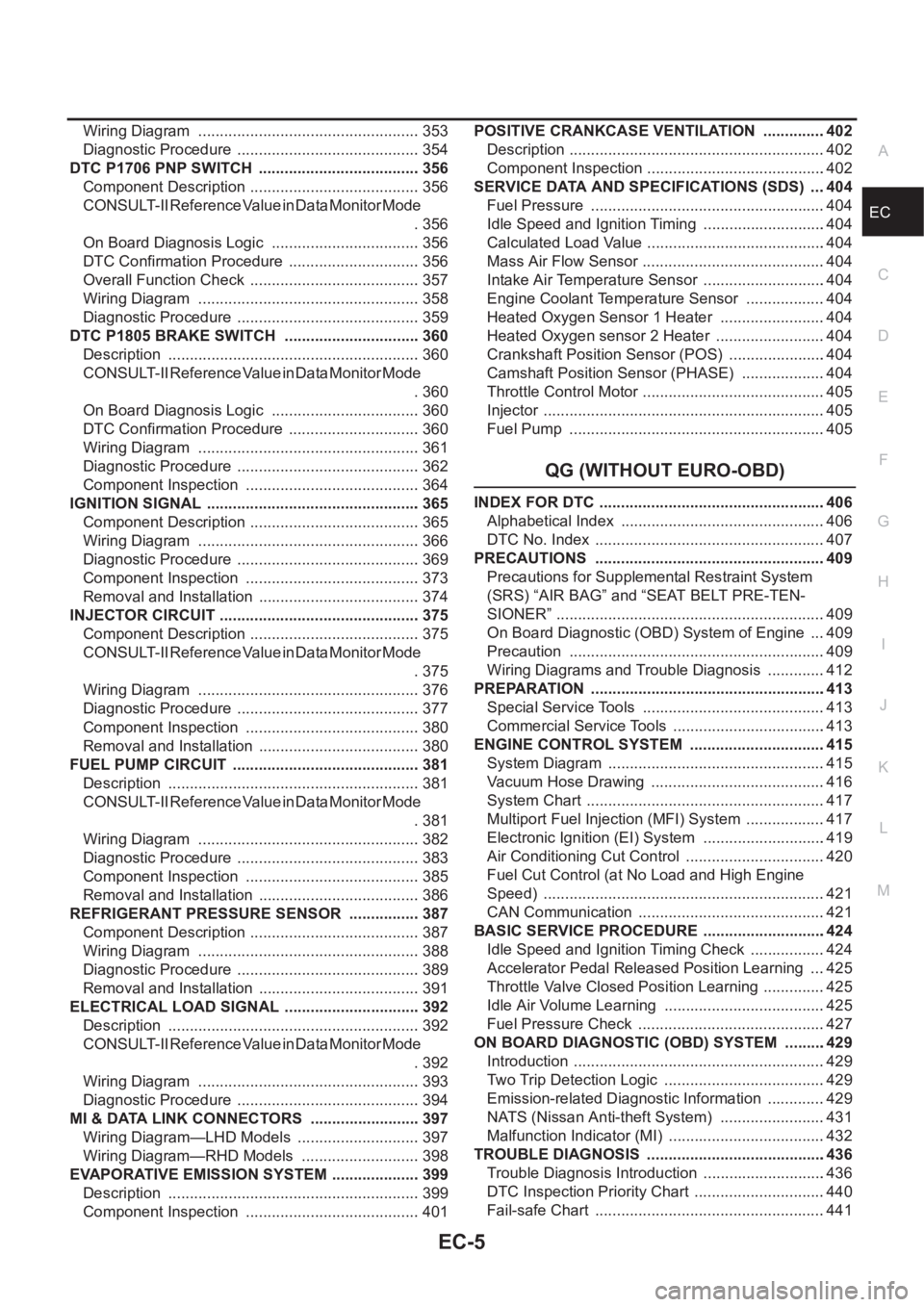
ECA Wiring Diagram .................................................... 353
Diagnostic Procedure ........................................... 354
DTC P1706 PNP SWITCH ...................................... 356
Component Description ........................................ 356
CONSULT-II Reference Value in Data Monitor Mode
. 356
On Board Diagnosis Logic ................................... 356
DTC Confirmation Procedure ............................... 356
Overall Function Check ........................................ 357
Wiring Diagram .................................................... 358
Diagnostic Procedure ........................................... 359
DTC P1805 BRAKE SWITCH ................................ 360
Description ........................................................... 360
CONSULT-II Reference Value in Data Monitor Mode
. 360
On Board Diagnosis Logic ................................... 360
DTC Confirmation Procedure ............................... 360
Wiring Diagram .................................................... 361
Diagnostic Procedure ........................................... 362
Component Inspection ......................................... 364
IGNITION SIGNAL .................................................. 365
Component Description ........................................ 365
Wiring Diagram .................................................... 366
Diagnostic Procedure ........................................... 369
Component Inspection ......................................... 373
Removal and Installation ...................................... 374
INJECTOR CIRCUIT ............................................... 375
Component Description ........................................ 375
CONSULT-II Reference Value in Data Monitor Mode
. 375
Wiring Diagram .................................................... 376
Diagnostic Procedure ........................................... 377
Component Inspection ......................................... 380
Removal and Installation ...................................... 380
FUEL PUMP CIRCUIT ............................................ 381
Description ........................................................... 381
CONSULT-II Reference Value in Data Monitor Mode
. 381
Wiring Diagram .................................................... 382
Diagnostic Procedure ........................................... 383
Component Inspection ......................................... 385
Removal and Installation ...................................... 386
REFRIGERANT PRESSURE SENSOR ................. 387
Component Description ........................................ 387
Wiring Diagram .................................................... 388
Diagnostic Procedure ........................................... 389
Removal and Installation ...................................... 391
ELECTRICAL LOAD SIGNAL ................................ 392
Description ...................................................
........ 392
CONSULT-II Reference Value in Data Monitor Mode
. 392
Wiring Diagram .................................................... 393
Diagnostic Procedure ........................................... 394
MI & DATA LINK CONNECTORS .......................... 397
Wiring Diagram—LHD Models ............................. 397
Wiring Diagram—RHD Models ............................ 398
EVAPORATIVE EMISSION SYSTEM ..................... 399
Description ........................................................... 399
Component Inspection ......................................... 401POSITIVE CRANKCASE VENTILATION ...............402
Description ............................................................402
Component Inspection ..........................................402
SERVICE DATA AND SPECIFICATIONS (SDS) ....404
Fuel Pressure .......................................................404
Idle Speed and Ignition Timing .............................404
Calculated Load Value ..........................................404
Mass Air Flow Sensor ...........................................404
Intake Air Temperature Sensor .............................404
Engine Coolant Temperature Sensor ...................404
Heated Oxygen Sensor 1 Heater .........................404
Heated Oxygen sensor 2 Heater ..........................404
Crankshaft Position Sensor (POS) .......................404
Camshaft Position Sensor (PHASE) ....................404
Throttle Control Motor ...........................................405
Injector ..................................................................405
Fuel Pump ............................................................405
QG (WITHOUT EURO-OBD)
INDEX FOR DTC .....................................................406
Alphabetical Index ................................................406
DTC No. Index ......................................................407
PRECAUTIONS ......................................................409
Precautions for Supplemental Restraint System
(SRS) “AIR BAG” and “SEAT BELT PRE-TEN-
SIONER” ...............................................................409
On Board Diagnostic (OBD) System of Engine ....409
Precaution ............................................................409
Wiring Diagrams and Trouble Diagnosis ..............412
PREPARATION .......................................................413
Special Service Tools ...........................................413
Commercial Service Tools ....................................413
ENGINE CONTROL SYSTEM ................................415
System Diagram ...................................................415
Vacuum Hose Drawing .........................................416
System Chart ........................................................417
Multiport Fuel Injection (MFI) System ...................417
Electronic Ignition (EI) System .............................419
Air Conditioning Cut Control .................................420
Fuel Cut Control (at No Load and High Engine
Speed) ..................................................................421
CAN Communication ............................................421
BASIC SERVICE PROCEDURE .............................424
Idle Speed and Ignition Timing Check ..................424
Accelerator Pedal Released Position Learning ....425
Throttle Valve Closed Position Learning ...............425
Idle Air Volume Learning ......................................425
Fuel Pressure Check ............................................427
ON BOARD DIAGNOSTIC (OBD) SYSTEM ..........429
Introduction ...........................................................429
Two Trip Detection Logic ......................................429
Emission-related Diagnostic Information ..............429
NATS (Nissan Anti-theft System) .........................431
Malfunction Indicator (MI) .....................................432
TROUBLE DIAGNOSIS ..........................................436
Trouble Diagnosis Introduction .............................436
DTC Inspection Priority Chart ...............................440
Fail-safe Chart ......................................................441
Page 477 of 3189
![NISSAN ALMERA N16 2003 Electronic Repair Manual DTC P0117, P0118 ECT SENSOR
EC-147
[QG (WITH EURO-OBD)]
C
D
E
F
G
H
I
J
K
L
MA
EC
Diagnostic ProcedureEBS00K5G
1.CHECK ECT SENSOR POWER SUPPLY CIRCUIT
1. Turn ignition switch “OFF”.
2. Disconnect NISSAN ALMERA N16 2003 Electronic Repair Manual DTC P0117, P0118 ECT SENSOR
EC-147
[QG (WITH EURO-OBD)]
C
D
E
F
G
H
I
J
K
L
MA
EC
Diagnostic ProcedureEBS00K5G
1.CHECK ECT SENSOR POWER SUPPLY CIRCUIT
1. Turn ignition switch “OFF”.
2. Disconnect](/manual-img/5/57350/w960_57350-476.png)
DTC P0117, P0118 ECT SENSOR
EC-147
[QG (WITH EURO-OBD)]
C
D
E
F
G
H
I
J
K
L
MA
EC
Diagnostic ProcedureEBS00K5G
1.CHECK ECT SENSOR POWER SUPPLY CIRCUIT
1. Turn ignition switch “OFF”.
2. Disconnect engine coolant temperature (ECT) sensor harness
connector.
3. Turn ignition switch “ON”.
4. Check voltage between ECT sensor terminal 1 and ground with
CONSULT-II or tester.
OK or NG
OK >> GO TO 2.
NG >> Repair open circuit or short to ground or short to power
in harness or connectors.
2.CHECK ECT SENSOR GROUND CIRCUIT FOR OPEN AND SHORT
1. Turn ignition switch “OFF”.
2. Check harness continuity between ECT sensor terminal 2 and engine ground.
Refer to Wiring Diagram.
3. Also check harness for short to ground and short to power.
OK or NG
OK >> GO TO 4.
NG >> GO TO 3.
3.DETECT MALFUNCTIONING PART
Check the following.
●Harness for open or short between engine coolant temperature sensor and ECM
●Harness for open or short between engine coolant temperature sensor and TCM (A/T models only)
>> Repair open circuit or short to ground or short to power in harness or connectors.
4.CHECK ENGINE COOLANT TEMPERATURE SENSOR
Refer to EC-148, "
Component Inspection" .
OK or NG
OK >> GO TO 5.
NG >> Replace engine coolant temperature sensor.
MBIB0097E
Voltage: Approximately 5V
PBIB0080E
Continuity should exist.
Page 662 of 3189
![NISSAN ALMERA N16 2003 Electronic Repair Manual EC-332
[QG (WITH EURO-OBD)]
DTC P1217 ENGINE OVER TEMPERATURE
3. CHECK COOLING FAN MOTORS CIRCUIT
1. Turn ignition switch “OFF”.
2. Disconnect cooling fan motor-1 harness connector and cool NISSAN ALMERA N16 2003 Electronic Repair Manual EC-332
[QG (WITH EURO-OBD)]
DTC P1217 ENGINE OVER TEMPERATURE
3. CHECK COOLING FAN MOTORS CIRCUIT
1. Turn ignition switch “OFF”.
2. Disconnect cooling fan motor-1 harness connector and cool](/manual-img/5/57350/w960_57350-661.png)
EC-332
[QG (WITH EURO-OBD)]
DTC P1217 ENGINE OVER TEMPERATURE
3. CHECK COOLING FAN MOTORS CIRCUIT
1. Turn ignition switch “OFF”.
2. Disconnect cooling fan motor-1 harness connector and cooling
fan motor-2 harness connector.
3. Check harness continuity between cooling fan relay-1 terminal 5
and cooling fan motor-1 terminal 1, cooling fan motor-1 terminal
2 and body ground.
Refer to Wiring Diagram.
4. Also check harness for short to ground and short to power.
5. Check harness continuity between cooling fan relay-1 terminal 7
and cooling fan motor-2 terminal 1, cooling fan motor-2 terminal
2 and body ground.
Refer to Wiring Diagram.
6. Also check harness for short to ground and short to power.
OK or NG
OK >> GO TO 4.
NG >> Repair open circuit or short to ground or short to power in harness or connectors.
4. CHECK COOLING FAN OUTPUT SIGNAL CIRCUIT FOR OPEN AND SHORT
1. Disconnect smart entrance control unit.
2. Check harness continuity between smart entrance control unit
terminal 33 and cooling fan relay-1 terminal 2.
Refer to Wiring Diagram.
3. Also check harness for short to ground and short to power.
OK or NG
OK >> GO TO 6.
NG >> GO TO 5.
5. DETECT MALFUNCTIONING PART
Check the following.
●Harness connectors E251, M182 (LHD models)
●Harness connectors E174, M159 (RHD models)
●Harness for open or short between smart entrance control unit and cooling fan relay-1
>> Repair open circuit or short to ground or short to power in harness or connectors.
6. CHECK COOLING FAN RELAY-1
Refer to EC-334, "
Component Inspection" .
OK or NG
OK >> GO TO 7.
NG >> Replace cooling fan relay.Continuity should exist.
Continuity should exist.
MBIB0252E
Continuity should exist.
MBIB0264E
Page 834 of 3189
![NISSAN ALMERA N16 2003 Electronic Repair Manual EC-504
[QG (WITHOUT EURO-OBD)]
DTC P0117, P0118 ECT SENSOR
Diagnostic Procedure
EBS00KFT
1. CHECK ECT SENSOR POWER SUPPLY CIRCUIT
1. Turn ignition switch “OFF”.
2. Disconnect engine coolant tem NISSAN ALMERA N16 2003 Electronic Repair Manual EC-504
[QG (WITHOUT EURO-OBD)]
DTC P0117, P0118 ECT SENSOR
Diagnostic Procedure
EBS00KFT
1. CHECK ECT SENSOR POWER SUPPLY CIRCUIT
1. Turn ignition switch “OFF”.
2. Disconnect engine coolant tem](/manual-img/5/57350/w960_57350-833.png)
EC-504
[QG (WITHOUT EURO-OBD)]
DTC P0117, P0118 ECT SENSOR
Diagnostic Procedure
EBS00KFT
1. CHECK ECT SENSOR POWER SUPPLY CIRCUIT
1. Turn ignition switch “OFF”.
2. Disconnect engine coolant temperature (ECT) sensor harness
connector.
3. Turn ignition switch “ON”.
4. Check voltage between ECT sensor terminal 1 and ground with
CONSULT-II or tester.
OK or NG
OK >> GO TO 2.
NG >> Repair open circuit or short to ground or short to power
in harness or connectors.
2. CHECK ECT SENSOR GROUND CIRCUIT FOR OPEN AND SHORT
1. Turn ignition switch “OFF”.
2. Check harness continuity between ECT sensor terminal 2 and engine ground.
Refer to Wiring Diagram.
3. Also check harness for short to ground and short to power.
OK or NG
OK >> GO TO 4.
NG >> GO TO 3.
3. DETECT MALFUNCTIONING PART
Check the following.
●Harness for open or short between engine coolant temperature sensor and ECM
●Harness for open or short between engine coolant temperature sensor and TCM (A/T models only)
>> Repair open circuit or short to ground or short to power in harness or connectors.
4. CHECK ENGINE COOLANT TEMPERATURE SENSOR
Refer to EC-505, "
Component Inspection" .
OK or NG
OK >> GO TO 5.
NG >> Replace engine coolant temperature sensor.
MBIB0097E
Voltage: Approximately 5V
PBIB0080E
Continuity should exist.
Page 934 of 3189
![NISSAN ALMERA N16 2003 Electronic Repair Manual EC-604
[QG (WITHOUT EURO-OBD)]
DTC P1217 ENGINE OVER TEMPERATURE
3. CHECK COOLING FAN MOTORS CIRCUIT
1. Turn ignition switch “OFF”.
2. Disconnect cooling fan motor-1 harness connector and c NISSAN ALMERA N16 2003 Electronic Repair Manual EC-604
[QG (WITHOUT EURO-OBD)]
DTC P1217 ENGINE OVER TEMPERATURE
3. CHECK COOLING FAN MOTORS CIRCUIT
1. Turn ignition switch “OFF”.
2. Disconnect cooling fan motor-1 harness connector and c](/manual-img/5/57350/w960_57350-933.png)
EC-604
[QG (WITHOUT EURO-OBD)]
DTC P1217 ENGINE OVER TEMPERATURE
3. CHECK COOLING FAN MOTORS CIRCUIT
1. Turn ignition switch “OFF”.
2. Disconnect cooling fan motor-1 harness connector and cooling
fan motor-2 harness connector.
3. Check harness continuity between cooling fan relay-1 terminal 5
and cooling fan motor-1 terminal 1, cooling fan motor-1 terminal
2 and body ground.
Refer to wiring diagram.
4. Also check harness for short to ground and short to power.
5. Check harness continuity between cooling fan relay-1 terminal 7
and cooling fan motor-2 terminal 1, cooling fan motor-2 terminal
2 and body ground.
Refer to wiring diagram.
6. Also check harness for short to ground and short to power.
OK or NG
OK >> GO TO 4.
NG >> Repair open circuit or short to ground or short to power in harness or connectors.
4. CHECK COOLING FAN OUTPUT SIGNAL CIRCUIT FOR OPEN AND SHORT
1. Disconnect smart entrance control unit.
2. Check harness continuity between smart entrance control unit
terminal 33 and cooling fan relay-1 terminal 2.
Refer to Wiring Diagram.
3. Also check harness for short to ground and short to power.
OK or NG
OK >> GO TO 6.
NG >> GO TO 5.
5. DETECT MALFUNCTIONING PART
Check the following.
●Harness connectors E251, M182 (LHD models)
●Harness connectors E174, M159 (RHD models)
●Harness for open or short between smart entrance control unit and cooling fan relay-1
>> Repair open circuit or short to ground or short to power in harness or connectors.
6. CHECK COOLING FAN RELAY-1
Refer to EC-606, "
Component Inspection" .
OK or NG
OK >> GO TO 7.
NG >> Replace cooling fan relay.Continuity should exist.
Continuity should exist.
MBIB0252E
Continuity should exist.
MBIB0264E
Page 1141 of 3189

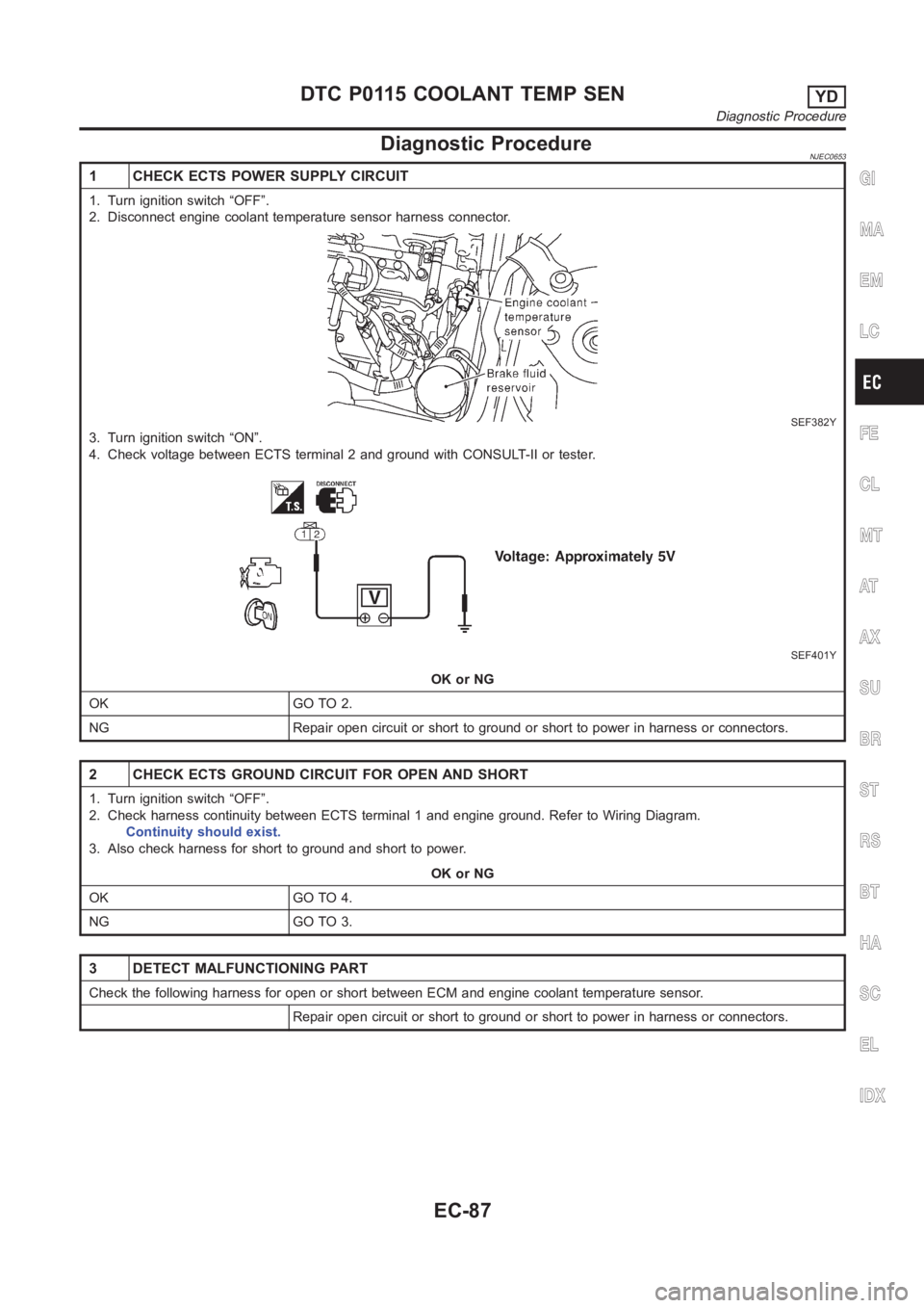
Diagnostic ProcedureNJEC0653
1 CHECK ECTS POWER SUPPLY CIRCUIT
1. Turn ignition switch “OFF”.
2. Disconnect engine coolant temperature sensor harness connector.
SEF382Y
3. Turn ignition switch “ON”.
4. Check voltage between ECTS terminal 2 and ground with CONSULT-II or tester.
SEF401Y
OK or NG
OK GO TO 2.
NG Repair open circuit or short to ground or short to power in harness or connectors.
2 CHECK ECTS GROUND CIRCUIT FOR OPEN AND SHORT
1. Turn ignition switch “OFF”.
2. Check harness continuity between ECTS terminal 1 and engine ground. Refer to Wiring Diagram.
Continuity should exist.
3. Also check harness for short to ground and short to power.
OK or NG
OK GO TO 4.
NG GO TO 3.
3 DETECT MALFUNCTIONING PART
Check the following harness for open or short between ECM and engine coolant temperature sensor.
Repair open circuit or short to ground or short to power in harness or connectors.
GI
MA
EM
LC
FE
CL
MT
AT
AX
SU
BR
ST
RS
BT
HA
SC
EL
IDX
DTC P0115 COOLANT TEMP SENYD
Diagnostic Procedure
EC-87
Page 1193 of 3189

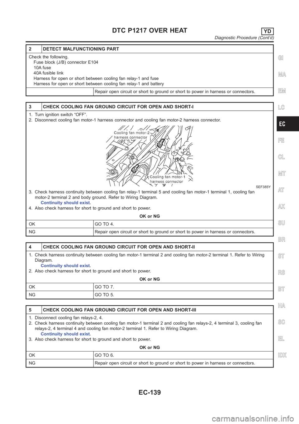
2 DETECT MALFUNCTIONING PART
Check the following.
Fuse block (J/B) connector E104
10A fuse
40A fusible link
Harness for open or short between cooling fan relay-1 and fuse
Harness for open or short between cooling fan relay-1 and battery
Repair open circuit or short to ground or short to power in harness or connectors.
3 CHECK COOLING FAN GROUND CIRCUIT FOR OPEN AND SHORT-I
1. Turn ignition switch “OFF”.
2. Disconnect cooling fan motor-1 harness connector and cooling fan motor-2 harness connector.
SEF385Y
3. Check harness continuity between cooling fan relay-1 terminal 5 and cooling fan motor-1 terminal 1, cooling fan
motor-2 terminal 2 and body ground. Refer to Wiring Diagram.
Continuity should exist.
4. Also check harness for short to ground and short to power.
OK or NG
OK GO TO 4.
NG Repair open circuit or short to ground or short to power in harness or connectors.
4 CHECK COOLING FAN GROUND CIRCUIT FOR OPEN AND SHORT-II
1. Check harness continuity between cooling fan motor-1 terminal 2 and cooling fan motor-2 terminal 1. Refer to Wiring
Diagram.
Continuity should exist.
2. Also check harness for short to ground and short to power.
OK or NG
OK GO TO 7.
NG GO TO 5.
5 CHECK COOLING FAN GROUND CIRCUIT FOR OPEN AND SHORT-III
1. Disconnect cooling fan relays-2, 4.
2. Check harness continuity between cooling fan motor-1 terminal 2 and cooling fan relays-2, 4 terminal 3, cooling fan
relays-2, 4 terminal 4 and cooling fan motor-2 terminal 1. Refer to Wiring Diagram.
Continuity should exist.
3. Also check harness for short to ground and short to power.
OK or NG
OK GO TO 6.
NG Repair open circuit or short to ground or short to power in harness or connectors.
GI
MA
EM
LC
FE
CL
MT
AT
AX
SU
BR
ST
RS
BT
HA
SC
EL
IDX
DTC P1217 OVER HEATYD
Diagnostic Procedure (Cont’d)
EC-139
Page 1196 of 3189

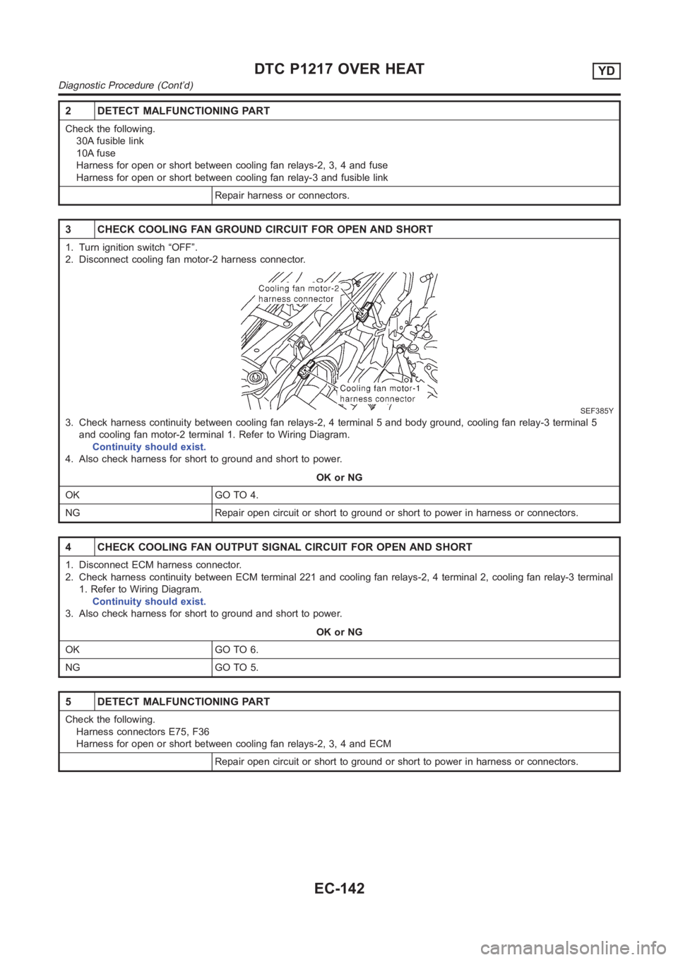
2 DETECT MALFUNCTIONING PART
Check the following.
30A fusible link
10A fuse
Harness for open or short between cooling fan relays-2, 3, 4 and fuse
Harness for open or short between cooling fan relay-3 and fusible link
Repair harness or connectors.
3 CHECK COOLING FAN GROUND CIRCUIT FOR OPEN AND SHORT
1. Turn ignition switch “OFF”.
2. Disconnect cooling fan motor-2 harness connector.
SEF385Y
3. Check harness continuity between cooling fan relays-2, 4 terminal 5 andbody ground, cooling fan relay-3 terminal 5
and cooling fan motor-2 terminal 1. Refer to Wiring Diagram.
Continuity should exist.
4. Also check harness for short to ground and short to power.
OK or NG
OK GO TO 4.
NG Repair open circuit or short to ground or short to power in harness or connectors.
4 CHECK COOLING FAN OUTPUT SIGNAL CIRCUIT FOR OPEN AND SHORT
1. Disconnect ECM harness connector.
2. Check harness continuity between ECM terminal 221 and cooling fan relays-2, 4 terminal 2, cooling fan relay-3 terminal
1. Refer to Wiring Diagram.
Continuity should exist.
3. Also check harness for short to ground and short to power.
OK or NG
OK GO TO 6.
NG GO TO 5.
5 DETECT MALFUNCTIONING PART
Check the following.
Harness connectors E75, F36
Harness for open or short between cooling fan relays-2, 3, 4 and ECM
Repair open circuit or short to ground or short to power in harness or connectors.
DTC P1217 OVER HEATYD
Diagnostic Procedure (Cont’d)
EC-142