2003 NISSAN ALMERA N16 starting
[x] Cancel search: startingPage 1 of 3189
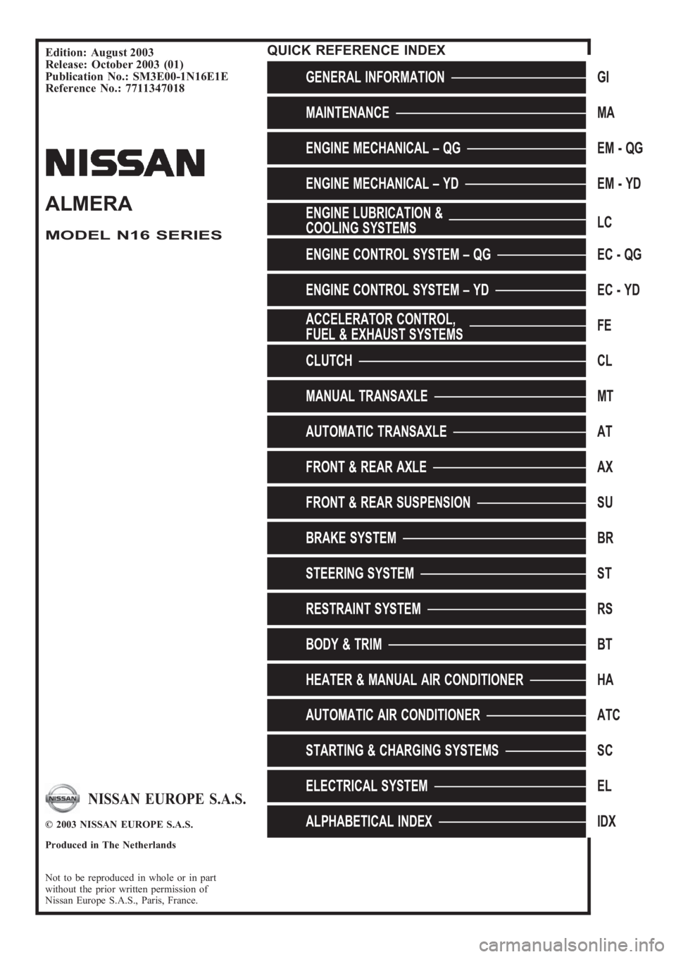
Edition: August 2003
Release: October 2003 (01)
Publication No.: SM3E00-1N16E1E
Reference No.: 7711347018
GENERAL INFORMATIONGI
MAINTENANCEMA
ENGINE MECHANICAL – QGEM-QG
ENGINE MECHANICAL – YDEM-YD
ENGINE LUBRICATION &
COOLING SYSTEMSLC
ENGINE CONTROL SYSTEM – QGEC - QG
ENGINE CONTROL SYSTEM – YDEC - YD
ACCELERATOR CONTROL,
FUEL & EXHAUST SYSTEMSFE
CLUTCHCL
MANUAL TRANSAXLEMT
AUTOMATIC TRANSAXLEAT
FRONT & REAR AXLEAX
FRONT & REAR SUSPENSIONSU
BRAKE SYSTEMBR
STEERING SYSTEMST
RESTRAINT SYSTEMRS
BODY & TRIMBT
HEATER & MANUAL AIR CONDITIONERHA
AUTOMATIC AIR CONDITIONERATC
STARTING & CHARGING SYSTEMSSC
ELECTRICAL SYSTEMEL
ALPHABETICAL INDEXIDX
ALMERA
MODEL N16 SERIES
NISSAN EUROPE S.A.S.
© 2003 NISSAN EUROPE S.A.S.
Produced in The Netherlands
Not to be reproduced in whole or in part
without the prior written permission of
Nissan Europe S.A.S., Paris, France.
QUICK REFERENCE INDEX
Page 2 of 3189
FOREWORD
This manual contains maintenance and repair procedures for NISSAN
ALMERA, model N16 series.
In order to assure your safety and the efficient functioning of the vehicle,
this manual should be read thoroughly. It is especially important that the
PRECAUTIONS in the GI section be completely understood before starting
any repair task.
All information in this manual is based on the latest product information
at the time of publication. The right is reserved to make changes in speci-
fications and methods at any time without notice.
IMPORTANT SAFETY NOTICE
The proper performance of service is essential for both the safety of the
technician and the efficient functioning of the vehicle.
The service methods in this Service Manual are described in such a man-
ner that the service may be performed safely and accurately.
Service varies with the procedures used, the skills of the technician and the
tools and parts available. Accordingly, anyone using service procedures,
tools or parts which are not specifically recommended by NISSAN must
first completely satisfy himself that neither his safety nor the vehicle’s
safety will be jeopardized by the service method selected.
NISSAN EUROPE S.A.S.
Service Engineering Section
Paris, France
Page 7 of 3189
SEF289H
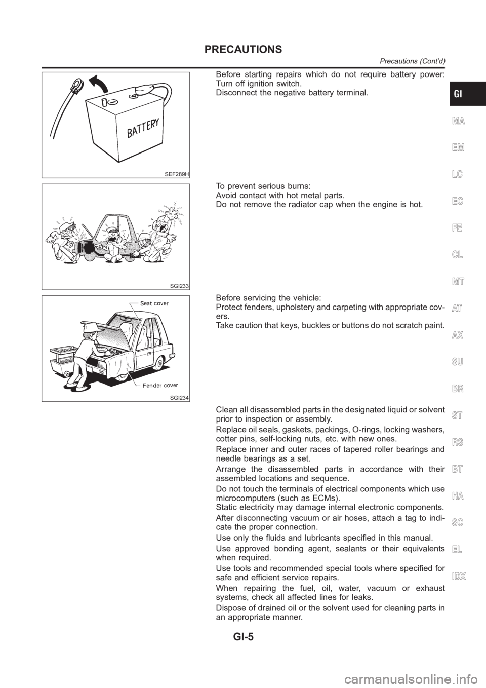
Before starting repairs which do not require battery power:
Turn off ignition switch.
Disconnect the negative battery terminal.
SGI233
To prevent serious burns:
Avoid contact with hot metal parts.
Do not remove the radiator cap when the engine is hot.
SGI234
Before servicing the vehicle:
Protect fenders, upholstery and carpeting with appropriate cov-
ers.
Take caution that keys, buckles or buttons do not scratch paint.
Clean all disassembled parts in the designated liquid or solvent
prior to inspection or assembly.
Replace oil seals, gaskets, packings, O-rings, locking washers,
cotter pins, self-locking nuts, etc. with new ones.
Replace inner and outer races of tapered roller bearings and
needle bearings as a set.
Arrange the disassembled parts in accordance with their
assembled locations and sequence.
Do not touch the terminals of electrical components which use
microcomputers (such as ECMs).
Static electricity may damage internal electronic components.
After disconnecting vacuum or air hoses, attach a tag to indi-
cate the proper connection.
Use only the fluids and lubricants specified in this manual.
Use approved bonding agent, sealants or their equivalents
when required.
Use tools and recommended special tools where specified for
safe and efficient service repairs.
When repairing the fuel, oil, water, vacuum or exhaust
systems, check all affected lines for leaks.
Dispose of drained oil or the solvent used for cleaning parts in
an appropriate manner.
MA
EM
LC
EC
FE
CL
MT
AT
AX
SU
BR
ST
RS
BT
HA
SC
EL
IDX
PRECAUTIONS
Precautions (Cont’d)
GI-5
Page 91 of 3189
![NISSAN ALMERA N16 2003 Electronic Repair Manual DRIVE BELTS
EM-13
[QG]
C
D
E
F
G
H
I
J
K
L
MA
EM
Removal and InstallationEBS00LQ0
REMOVAL
●Loosen each belt while referring to “Tension Adjustment”, and remove them one by one starting from the
NISSAN ALMERA N16 2003 Electronic Repair Manual DRIVE BELTS
EM-13
[QG]
C
D
E
F
G
H
I
J
K
L
MA
EM
Removal and InstallationEBS00LQ0
REMOVAL
●Loosen each belt while referring to “Tension Adjustment”, and remove them one by one starting from the](/manual-img/5/57350/w960_57350-90.png)
DRIVE BELTS
EM-13
[QG]
C
D
E
F
G
H
I
J
K
L
MA
EM
Removal and InstallationEBS00LQ0
REMOVAL
●Loosen each belt while referring to “Tension Adjustment”, and remove them one by one starting from the
one in front.
INSTALLATION
1. Install belts to pulley in reverse order of removal.
2. Adjust belt tension.
CAUTION:
●When checking belt tension immediately after installation, first, adjust to specified value. Then,
after turning crankshaft more than two turns, re-adjust to specified value to avoid variation in
deflection between pulleys.
●Tighten idler pulley lock nut by hand and measure tension without looseness.
3. Tighten each adjusting bolt and nut to the specified torque.
4. Make sure that tension of each belt is within the standard.
Page 120 of 3189
![NISSAN ALMERA N16 2003 Electronic Repair Manual EM-42
[QG]
CAMSHAFT
Valve Lifter Hole Diameter
●Using inside micrometer, measure diameter of valve lifter hole of
cylinder head.
Calculation of Valve Lifter Clearance
(Valve lifter clearance) = (hol NISSAN ALMERA N16 2003 Electronic Repair Manual EM-42
[QG]
CAMSHAFT
Valve Lifter Hole Diameter
●Using inside micrometer, measure diameter of valve lifter hole of
cylinder head.
Calculation of Valve Lifter Clearance
(Valve lifter clearance) = (hol](/manual-img/5/57350/w960_57350-119.png)
EM-42
[QG]
CAMSHAFT
Valve Lifter Hole Diameter
●Using inside micrometer, measure diameter of valve lifter hole of
cylinder head.
Calculation of Valve Lifter Clearance
(Valve lifter clearance) = (hole diameter of valve lifter) – (outer diam-
eter of valve lifter).
●When out of specified range, referring to each specification of outer and inner diameter, replace either or
both valve lifter and cylinder head.
Valve ClearanceEBS00LQC
INSPECTION
●The following procedure is applicable when: Components related to camshafts or valves are removed,
installed, or replaced. Drivability concerns (poor starting, poor idling, noise) are caused by valve clearance
aging.
1. Warm up engine, and stop.
2. Remove RH splash cover (integrated with undercover).
3. Remove rocker cover. Refer to EM-29, "
ROCKER COVER" .
4. Turn crankshaft pulley clockwise (viewed from front) to align yel-
low paint with timing indicator.
5. At this point, confirm that both intake and exhaust cam noses on
No. 1 cylinder face outward. (No. 1 cylinder is at TDC of its com-
pression stroke.)
●If not, turn crankshaft pulley more.
NOTE:
Or, valves to be checked when No. 4 cylinder is at TDC of its
compression stroke can be checked first following step 8.
6. Referring to figure, measure valve clearances of valves with × in
table below using a thickness gauge.Standard (Intake and exhaust)
: 30.000 - 30.021 mm (1.1811 - 1.1819 in) dia.
Standard (Intake and exhaust)
: 0.025 - 0.061 mm (0.0010 - 0.0024 in)
SEM867E
MBIB0222E
Cylinder No.1 No.2 No.3 No.4
Valve INT EXH INT EXH INT EXH INT EXH
No. 1 cylinder at
TDC of its compres-
sion stroke××× ×
MBIB0223E
MBIB0224E
Page 192 of 3189
NJEM0051
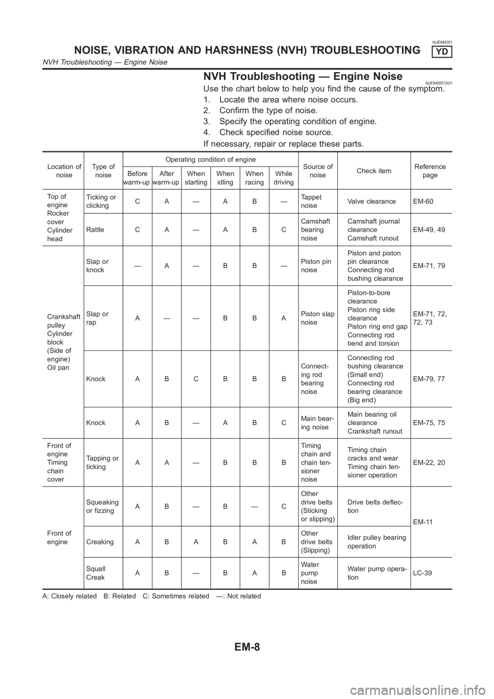
NVH Troubleshooting — Engine NoiseNJEM0051S01Use the chart below to help you find the cause of the symptom.
1. Locate the area where noise occurs.
2. Confirm the type of noise.
3. Specify the operating condition of engine.
4. Check specified noise source.
If necessary, repair or replace these parts.
Location of
noiseTy p e o f
noiseOperating condition of engine
Source of
noiseCheck itemReference
page Before
warm-upAfter
warm-upWhen
startingWhen
idlingWhen
racingWhile
driving
To p o f
engine
Rocker
cover
Cylinder
headTicking or
clickingC A—A B—Tappet
noiseValve clearance EM-60
Rattle C A — A B CCamshaft
bearing
noiseCamshaft journal
clearance
Camshaft runoutEM-49, 49
Crankshaft
pulley
Cylinder
block
(Side of
engine)
Oil panSlap or
knock—A—B B—Piston pin
noisePiston and piston
pin clearance
Connecting rod
bushing clearanceEM-71, 79
Slap or
rapA——B B APiston slap
noisePiston-to-bore
clearance
Piston ring side
clearance
Piston ring end gap
Connecting rod
bend and torsionEM-71, 72,
72, 73
Knock A B C B B BConnect-
ing rod
bearing
noiseConnecting rod
bushing clearance
(Small end)
Connecting rod
bearing clearance
(Big end)EM-79, 77
Knock A B — A B CMain bear-
ing noiseMain bearing oil
clearance
Crankshaft runoutEM-75, 75
Front of
engine
Timing
chain
coverTapping or
tickingAA—BBBTiming
chain and
chain ten-
sioner
noiseTiming chain
cracks and wear
Timing chain ten-
sioner operationEM-22, 20
Front of
engineSqueaking
or fizzingA B—B—COther
drive belts
(Sticking
or slipping)Drive belts deflec-
tion
EM-11
CreakingABABABOther
drive belts
(Slipping)Idler pulley bearing
operation
Squall
CreakAB—BABWater
pump
noiseWater pump opera-
tionLC-39
A: Closely related B: Related C: Sometimes related —: Not related
NOISE, VIBRATION AND HARSHNESS (NVH) TROUBLESHOOTINGYD
NVH Troubleshooting — Engine Noise
EM-8
Page 236 of 3189
SEM934C
JEM157G
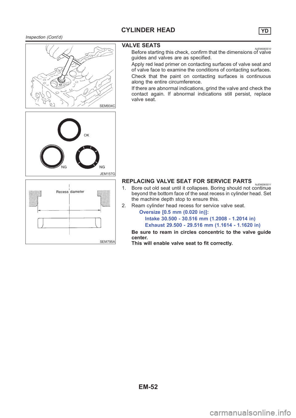
VALVE SEATSNJEM0065S10Before starting this check, confirm that the dimensions of valve
guides and valves are as specified.
Apply red lead primer on contacting surfaces of valve seat and
of valve face to examine the conditions of contacting surfaces.
Check that the paint on contacting surfaces is continuous
along the entire circumference.
If there are abnormal indications, grind the valve and check the
contact again. If abnormal indications still persist, replace
valve seat.
SEM795A
REPLACING VALVE SEAT FOR SERVICE PARTSNJEM0065S111. Bore out old seat until it collapses. Boring should not continue
beyond the bottom face of the seat recess in cylinder head. Set
the machine depth stop to ensure this.
2. Ream cylinder head recess for service valve seat.
Oversize [0.5 mm (0.020 in)]:
Intake 30.500 - 30.516 mm (1.2008 - 1.2014 in)
Exhaust 29.500 - 29.516 mm (1.1614 - 1.1620 in)
Be sure to ream in circles concentric to the valve guide
center.
This will enable valve seat to fit correctly.
CYLINDER HEADYD
Inspection (Cont’d)
EM-52
Page 249 of 3189
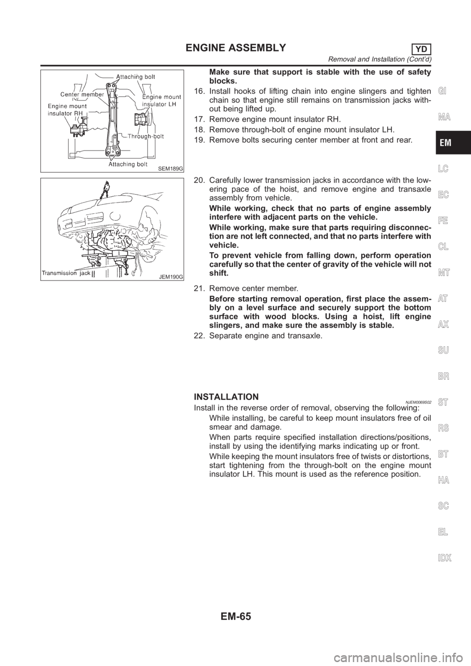
SEM189G
Make sure that support is stable with the use of safety
blocks.
16. Install hooks of lifting chain into engine slingers and tighten
chain so that engine still remains on transmission jacks with-
out being lifted up.
17. Remove engine mount insulator RH.
18. Remove through-bolt of engine mount insulator LH.
19. Remove bolts securing center member at front and rear.
JEM190G
20. Carefully lower transmission jacks in accordance with the low-
ering pace of the hoist, and remove engine and transaxle
assembly from vehicle.
While working, check that no parts of engine assembly
interfere with adjacent parts on the vehicle.
While working, make sure that parts requiring disconnec-
tion are not left connected, and that no parts interfere with
vehicle.
To prevent vehicle from falling down, perform operation
carefully so that the center of gravity of the vehicle will not
shift.
21. Remove center member.
Before starting removal operation, first place the assem-
bly on a level surface and securely support the bottom
surface with wood blocks. Using a hoist, lift engine
slingers, and make sure the assembly is stable.
22. Separate engine and transaxle.
INSTALLATIONNJEM0069S02Install in the reverse order of removal, observing the following:
While installing, be careful to keep mount insulators free of oil
smear and damage.
When parts require specified installation directions/positions,
install by using the identifying marks indicating up or front.
While keeping the mount insulators free of twists or distortions,
start tightening from the through-bolt on the engine mount
insulator LH. This mount is used as the reference position.
GI
MA
LC
EC
FE
CL
MT
AT
AX
SU
BR
ST
RS
BT
HA
SC
EL
IDX
ENGINE ASSEMBLYYD
Removal and Installation (Cont’d)
EM-65