Page 2176 of 3189

SMA525A
On-vehicle Service
REAR SUSPENSION PARTSNJSU0029Check axle and suspension parts for excessive play, wear or dam-
age.
Shake each rear wheel to check for excessive play.
SSU036
Retighten all nuts and bolts to the specified torque.
Tightening torque:
Refer to “REAR SUSPENSION”, SU-17.
SMA113
Check shock absorber for oil leakage or other damage.
Check wheelarch height. Refer to “On-vehicle Service”,
“FRONT SUSPENSION PARTS”, SU-6.
REAR WHEEL ALIGNMENTNJSU0030Before checking rear wheel alignment, be sure to make a prelimi-
nary inspection (Unladen*).
*: Fuel, radiator coolant and engine oil full. Spare tire, jack, hand
tools and mats in designated positions.
SFA975B
Preliminary InspectionNJSU0030S011. Check tires for wear and improper inflation.
2. Check wheels for deformation, cracks and other damage.
If deformed, remove wheel and check wheel runout.
a. Remove tire from wheel and mount wheel on a tire balance
machine.
b. Set dial indicator as shown in the illustration.
Wheel runout (Dial indicator value):
Refer to SDS, SU-15.
3. Check front wheel bearings for looseness.
REAR SUSPENSION
On-vehicle Service
SU-18
Page 2183 of 3189
Service Data and Specifications (SDS)
GENERAL SPECIFICATIONS (REAR)=NJSU0039
Suspension type Multi-link beam suspension
Shock absorber type Double-acting hydraulic
REAR WHEEL ALIGNMENT (UNLADEN*)NJSU0040
Camber
Degree minute (Decimal degree)Minimum −2°15′(−2.25°)
Nominal −1°03′(−1.05°)
Maximum −0°45′(−0.75°)
Total toe-in Distance (A − B)
mm (in)Minimum −2 (−0.08)
Nominal 2 (0.08)
Maximum 6 (0.24)
Angle (left plus right)
Degree minute (Decimal degree)Minimum −0°12′(−0.20°)
Nominal 0°12′(0.20°)
Maximum 0°36′(0.60°)
*: Fuel, radiator coolant and engine oil full. Spare tire, jack, hand toolsand mats in designated positions.
GI
MA
EM
LC
EC
FE
CL
MT
AT
AX
BR
ST
RS
BT
HA
SC
EL
IDX
REAR SUSPENSION
Service Data and Specifications (SDS)
SU-25
Page 2190 of 3189
NJBR0005
NVH Troubleshooting ChartNJBR0005S01Use the table below to help you find the cause of the symptom. If necessary, repair or replace these parts.
Reference page
BR-27, 31
BR-27, 31
BR-27, 31
—
—
BR-29, 35
—
—
—
BR-29, 35
AX-3
SU-4, AX-3
SU-4
SU-4
ST-5
SUSPECTED PARTS
(Possible cause)
Pads - damaged
Pads - uneven wear
Shims damaged
Rotor imbalance
Rotor damage
Rotor runout
Rotor deformation
Rotor deflection
Rotor rust
Rotor thickness variation
DRIVE SHAFT
AXLE AND SUSPENSION
TIRES
ROAD WHEEL
STEERING
Symptom BRAKENoise X X X———————XXXXX
Shake ——— X ——————XXXXX
Shimmy, Jud-
der———XXXXXXX—XXXX
X: Applicable
—: Not Applicable
NOISE, VIBRATION AND HARSHNESS (NVH) TROUBLESHOOTING
NVH Troubleshooting Chart
BR-6
Page 2191 of 3189

SBR451D
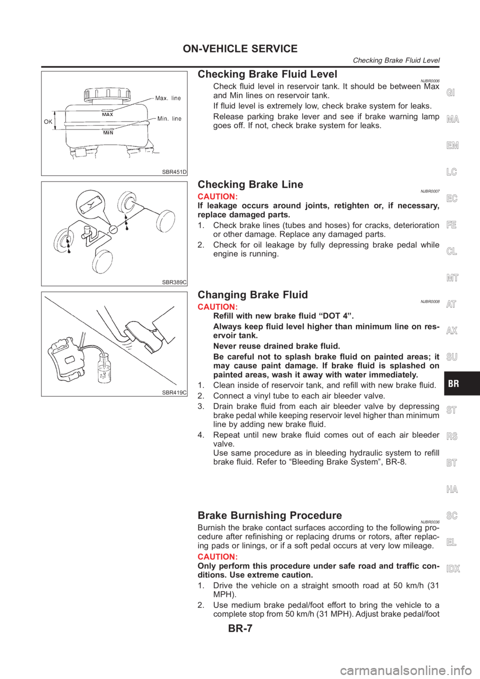
Checking Brake Fluid LevelNJBR0006Check fluid level in reservoir tank. It should be between Max
and Min lines on reservoir tank.
If fluid level is extremely low, check brake system for leaks.
Release parking brake lever and see if brake warning lamp
goes off. If not, check brake system for leaks.
SBR389C
Checking Brake LineNJBR0007CAUTION:
If leakage occurs around joints, retighten or, if necessary,
replace damaged parts.
1. Check brake lines (tubes and hoses) for cracks, deterioration
or other damage. Replace any damaged parts.
2. Check for oil leakage by fully depressing brake pedal while
engine is running.
SBR419C
Changing Brake FluidNJBR0008CAUTION:
Refill with new brake fluid “DOT 4”.
Always keep fluid level higher than minimum line on res-
ervoir tank.
Never reuse drained brake fluid.
Be careful not to splash brake fluid on painted areas; it
may cause paint damage. If brake fluid is splashed on
painted areas, wash it away with water immediately.
1. Clean inside of reservoir tank, and refill with new brake fluid.
2. Connect a vinyl tube to each air bleeder valve.
3. Drain brake fluid from each air bleeder valve by depressing
brake pedal while keeping reservoir level higher than minimum
line by adding new brake fluid.
4. Repeat until new brake fluid comes out of each air bleeder
valve.
Use same procedure as in bleeding hydraulic system to refill
brake fluid. Refer to “Bleeding Brake System”, BR-8.
Brake Burnishing ProcedureNJBR0036Burnish the brake contact surfaces according to the following pro-
cedure after refinishing or replacing drums or rotors, after replac-
ing pads or linings, or if a soft pedal occurs at very low mileage.
CAUTION:
Only perform this procedure under safe road and traffic con-
ditions. Use extreme caution.
1. Drive the vehicle on a straight smooth road at 50 km/h (31
MPH).
2. Use medium brake pedal/foot effort to bring the vehicle to a
complete stop from 50 km/h (31 MPH). Adjust brake pedal/foot
GI
MA
EM
LC
EC
FE
CL
MT
AT
AX
SU
ST
RS
BT
HA
SC
EL
IDX
ON-VEHICLE SERVICE
Checking Brake Fluid Level
BR-7
Page 2193 of 3189
Hydraulic CircuitNJBR0010
YBR317
RemovalNJBR0011CAUTION:
Be careful not to splash brake fluid on painted areas; it
may cause paint damage. If brake fluid is splashed on
painted areas, wash it away with water immediately.
All hoses must be free from excessive bending, twisting
and pulling.
For ball & ramp type rear caliper, care should be taken as
not to let air enter the body.
1. Remove flare nut connecting brake tube and hose, then with-
draw lock spring.
GI
MA
EM
LC
EC
FE
CL
MT
AT
AX
SU
ST
RS
BT
HA
SC
EL
IDX
BRAKE HYDRAULIC LINE
Hydraulic Circuit
BR-9
Page 2195 of 3189

SBR822BA
SBR823BA
Dual Proportioning ValveNJBR0149INSPECTIONNJBR0149S01CAUTION:
Carefully monitor brake fluid level at master cylinder.
Use new brake fluid “DOT 4”.
Be careful not to splash brake fluid on painted areas; it
may cause paint damage. If brake fluid is splashed on
paint areas, wash it away with water immediately.
Depress pedal slowly when raising front brake pressure.
Check rear brake pressure at least 2 seconds after front
brake pressure reaches specified value.
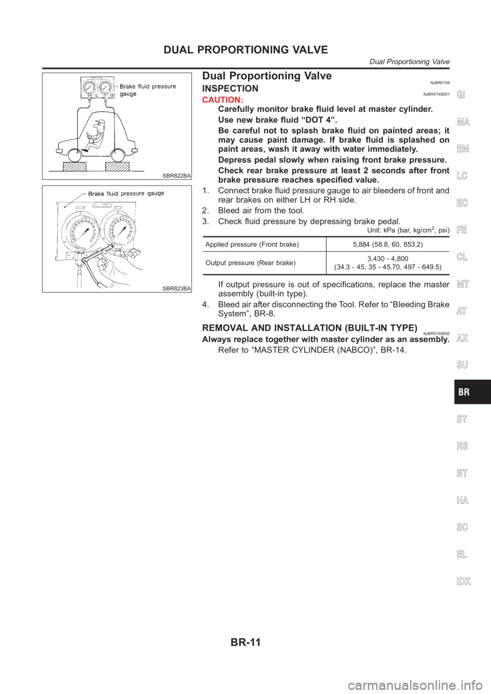
1. Connect brake fluid pressure gauge to air bleeders of front and
rear brakes on either LH or RH side.
2. Bleed air from the tool.
3. Check fluid pressure by depressing brake pedal.
Unit: kPa (bar, kg/cm2, psi)
Applied pressure (Front brake) 5,884 (58.8, 60, 853.2)
Output pressure (Rear brake)3,430 - 4,800
(34.3 - 45, 35 - 45.70, 497 - 649.5)
If output pressure is out of specifications, replace the master
assembly (built-in type).
4. Bleed air after disconnecting the Tool. Refer to “Bleeding Brake
System”, BR-8.
REMOVAL AND INSTALLATION (BUILT-IN TYPE)NJBR0149S02Always replace together with master cylinder as an assembly.
Refer to “MASTER CYLINDER (NABCO)”, BR-14.
GI
MA
EM
LC
EC
FE
CL
MT
AT
AX
SU
ST
RS
BT
HA
SC
EL
IDX
DUAL PROPORTIONING VALVE
Dual Proportioning Valve
BR-11
Page 2198 of 3189
RemovalNJBR0151
NBR351
1. Reservoir cap
2. Oil filter
3. Reservoir tank4. Seal
5. Cylinder body
6. Secondary piston assembly7. Primary piston assembly
8. Stopper cap
CAUTION:
Be careful not to splash brake fluid on painted areas; it may
cause paint damage. If brake fluid is splashed on painted
areas, wash it away with water immediately.
1. Connect a vinyl tube to air bleeder valve.
2. Drain brake fluid from each air bleeder valve, depressing brake
pedal to empty fluid from master cylinder.
3. Remove brake pipe flare nuts.
4. Remove master cylinder mounting nuts.
MASTER CYLINDER (NABCO)
Removal
BR-14
Page 2201 of 3189
RemovalNJBR0117
SBR766E
1. Reservoir cap
2. Oil filter (ABS models only)
3. Reservoir tank
4. Seal5. Cylinder body
6. Elastic pin
7. Piston stopper pin8. Secondary piston assembly
9. Primary piston assembly
10. Circlip
CAUTION:
Be careful not to splash brake fluid on painted areas; it may
cause paint damage. If brake fluid is splashed on painted
areas, wash it away with water immediately.
1. Connect a vinyl tube to front caliper air bleeder valve.
2. Drain brake fluid from each front caliper air bleeder valve,
depressing brake pedal to empty fluid from master cylinder.
3. Remove brake pipe flare nuts.
4. Remove master cylinder mounting nuts.
SBR231E
DisassemblyNJBR01181. Drive out elastic pin from cylinder body.
2. Remove reservoir tank and seals.
GI
MA
EM
LC
EC
FE
CL
MT
AT
AX
SU
ST
RS
BT
HA
SC
EL
IDX
MASTER CYLINDER [BOSCH (NABCO)]
Removal
BR-17