2003 NISSAN ALMERA N16 iat
[x] Cancel search: iatPage 2502 of 3189
SEL451XA
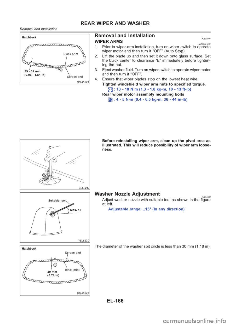
Removal and InstallationNJEL0301WIPER ARMSNJEL0301S011. Prior to wiper arm installation, turn on wiper switch to operate
wiper motor and then turn it “OFF” (Auto Stop).
2. Lift the blade up and then set it down onto glass surface. Set
the black center to clearance “E” immediately before tighten-
ing the nut.
3. Eject washer fluid. Turn on wiper switch to operate wiper motor
and then turn it “OFF”.
4. Ensure that wiper blades stop on the lowest heat wire.
Tighten windshield wiper arm nuts to specified torque.
: 13 - 18 N·m (1.3 - 1.8 kg-m, 10 - 13 ft-lb)
Rear wiper motor assembly mounting bolts
: 4 - 5 N·m (0.4 - 0.5 kg-m, 36 - 44 in-lb)
SEL024J
Before reinstalling wiper arm, clean up the pivot area as
illustrated. This will reduce possibility of wiper arm loose-
ness.
YEL823D
Washer Nozzle AdjustmentNJEL0302Adjust washer nozzle with suitable tool as shown in the figure
at left.
Adjustable range:±15° (In any direction)
SEL452XA
The diameter of the washer spit circle is less than 30 mm (1.18 in).
REAR WIPER AND WASHER
Removal and Installation
EL-166
Page 2529 of 3189
NATS AUDIO LINKNJEL0497S12DescriptionNJEL0497S1201The link with the NATS IMMU implies that the audio unit can basically only beoperated if connected to the
matching NATS IMMU to which the audio unit was initially fitted on the production line.
Since radio operation is impossible after the link with the NATS is disrupted theft of the audio unit is basically
useless since special equipment is required to reset the audio unit.
Initialization process for audio units that are linked to the NATS IMMU
Perform initialization with CONSULT-II
For initialization, refer to “CONSULT-II operation manual NATS”.
Normal operation
Each time the audio unit is switched on afterwards, the audio unit code willbe verified between the audio unit
and the NATS before the audio unit becomes operational.
When the radio is locked
When NATS link problems occur “SECURE” message will be displayed in three ways indicating three differ-
ent NATS link problems.
“Secure” on a red background indicates that there is a problem in the link between Navi control unit and Audio,
suggesting that there is either a Navigation system fault or the Navi control unit has previously been fitted in
another vehicle.
“Secure” on a green background indicates that there is a problem in the linkbetween NATS IMMU and Audio,
suggesting that there is an audio fault or the audio unit has previously been fitted in another vehicle.
“Secure” on a yellow background indicates that the transponder (NATS key)is not working correctly or it has
previously been fitted in another vehicle.
When a “Secure” message (of any type) is displayed, it can be cleared by re-initializing the NATS system using
CONSULT-II and the associated Immobilizer PIN code (there is no need to return the audio to a Clarion ser-
vice centre). If re-initializing fails to clear a “Secure” message then the component (identified by background
color) is faulty and should be replaced.
NOTE:
When the “Secure” is displayed on VFD display or audio unit, the communication of IMMU and radio, radio
unit or transponder has problem.
Service ProcedureNJEL0497S1202
Item Service procedure Description
Battery disconnection No additional action required. —
Radio needs repair Repair needs to be done by authorized
representative of radio manufacturer since
radio cannot be operated unless it is reset
to NEW state, using special decoding
equipment.—
Replacement of radio by new part No additional action required. Radio is delivered in NEW state.
Transferring radio to another vehicle/
replacement of radio by an “old” partRadio needs to be reset by using CON-
SULT-II and the associated Immobi PIN
code (there is no need to return the audio
or Navi units to a Clarion service centre).—
Replacement of IMMU The communication between IMMU and
radio need to be reset by using CON-
SULT-II and the associated Immobi PIN
code.After switching on the radio, it will display
“SECURE” on a green background.
No communication from IMMU to radio 1. If NATS is malfunctioning, check NATS
system.
2. After NATS is repaired, reset radio to
“Secure” on a green background state
by using CONSULT-II and the associ-
ated Immobilizer PIN code (there is no
need to return the audio to a Clarion
service centre).After switching on the radio, the display
unit will display “SECURE” on a green
background. Further use of radio is
impossible until communication is estab-
lished again, or after radio is reset by
using CONSULT-II and the associated
Immobilizer PIN code (there is no need to
return the audio to a Clarion service cen-
tre).
GI
MA
EM
LC
EC
FE
CL
MT
AT
AX
SU
BR
ST
RS
BT
HA
SC
IDX
AUDIO
System Description (Cont’d)
EL-193
Page 2637 of 3189
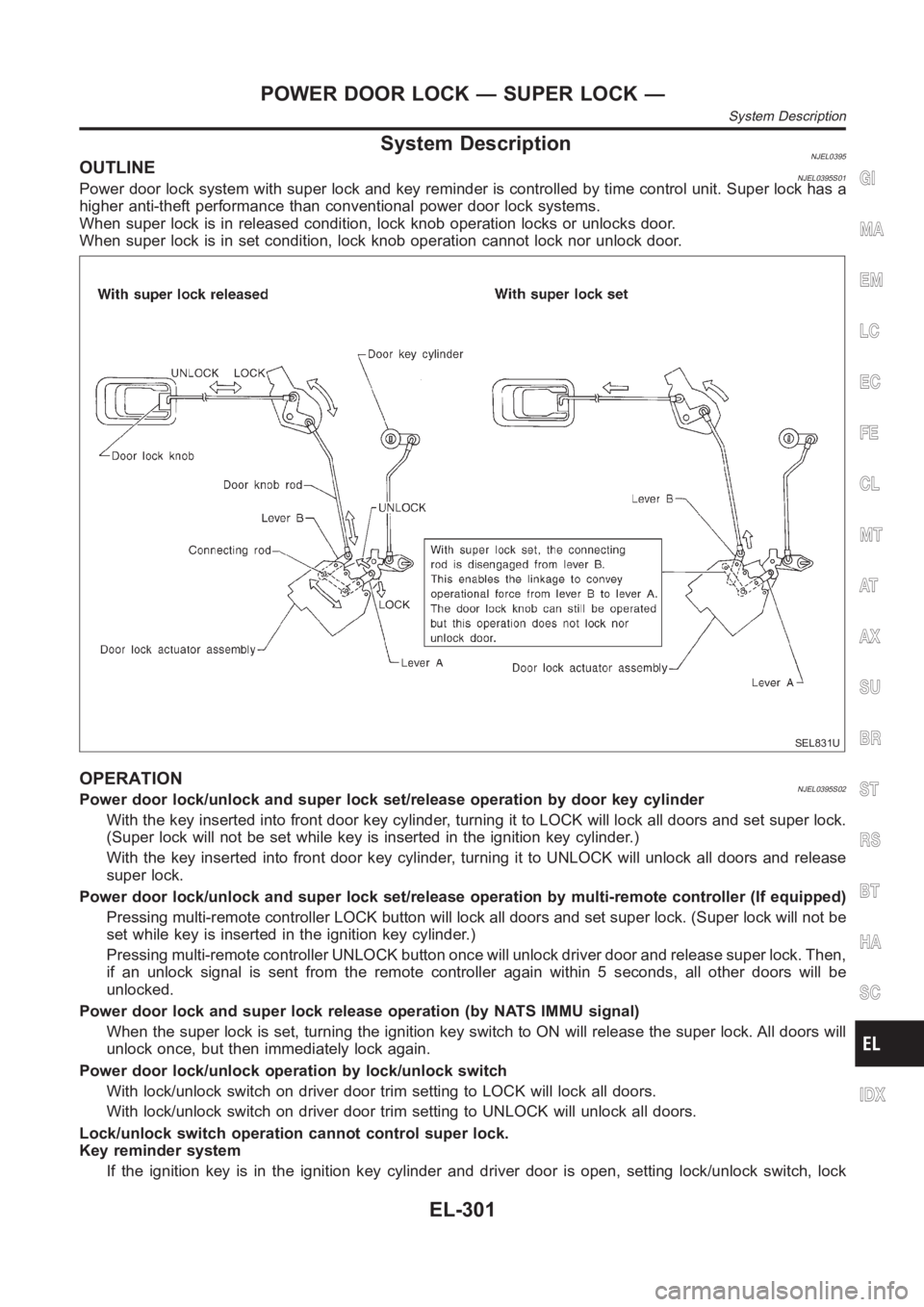
System DescriptionNJEL0395OUTLINENJEL0395S01Power door lock system with super lock and key reminder is controlled by time control unit. Super lock has a
higher anti-theft performance than conventional power door lock systems.
When super lock is in released condition, lock knob operation locks or unlocks door.
When super lock is in set condition, lock knob operation cannot lock nor unlock door.
SEL831U
OPERATIONNJEL0395S02Power door lock/unlock and super lock set/release operation by door key cylinder
With the key inserted into front door key cylinder, turning it to LOCK will lock all doors and set super lock.
(Super lock will not be set while key is inserted in the ignition key cylinder. )
With the key inserted into front door key cylinder, turning it to UNLOCK will unlock all doors and release
super lock.
Power door lock/unlock and super lock set/release operation by multi-remote controller (If equipped)
Pressing multi-remote controller LOCK button will lock all doors and set super lock. (Super lock will not be
set while key is inserted in the ignition key cylinder.)
Pressing multi-remote controller UNLOCK button once will unlock driver door and release super lock. Then,
if an unlock signal is sent from the remote controller again within 5 seconds, all other doors will be
unlocked.
Power door lock and super lock release operation (by NATS IMMU signal)
When the super lock is set, turning the ignition key switch to ON will release the super lock. All doors will
unlock once, but then immediately lock again.
Power door lock/unlock operation by lock/unlock switch
With lock/unlock switch on driver door trim setting to LOCK will lock all doors.
With lock/unlock switch on driver door trim setting to UNLOCK will unlock all doors.
Lock/unlock switch operation cannot control super lock.
Key reminder system
If the ignition key is in the ignition key cylinder and driver door is open, setting lock/unlock switch, lock
GI
MA
EM
LC
EC
FE
CL
MT
AT
AX
SU
BR
ST
RS
BT
HA
SC
IDX
POWER DOOR LOCK — SUPER LOCK —
System Description
EL-301
Page 2638 of 3189
knob, key or multi-remote controller to “LOCK” locks the door once but thenimmediately unlocks all doors.
(signal from door unlock sensor driver side)
System initialization
System initialization is required when battery cables are reconnected. Conduct the following to release
super lock once;
— insert the key into the ignition key cylinder and turn it to ON.
— LOCK/UNLOCK operation using door key cylinder or multi-remote controller.
POWER DOOR LOCK — SUPER LOCK —
System Description (Cont’d)
EL-302
Page 2712 of 3189
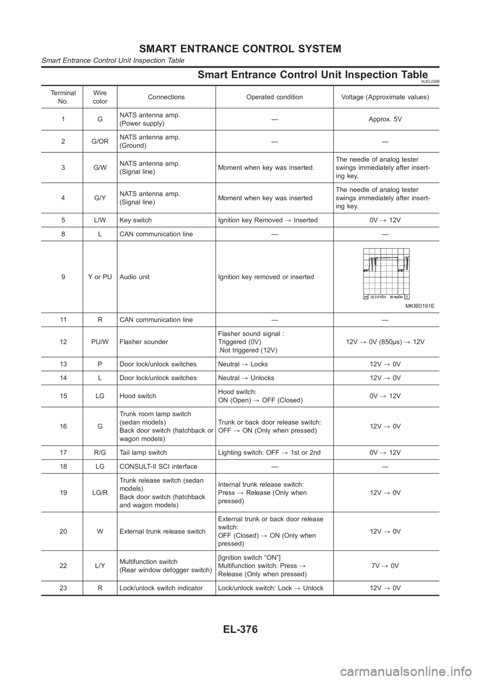
Smart Entrance Control Unit Inspection TableNJEL0586
Terminal
No.Wire
colorConnections Operated condition Voltage (Approximate values)
1GNATS antenna amp.
(Power supply)— Approx. 5V
2 G/ORNATS antenna amp.
(Ground)——
3 G/WNATS antenna amp.
(Signal line)Moment when key was inserted.The needle of analog tester
swings immediately after insert-
ing key.
4 G/YNATS antenna amp.
(Signal line)Moment when key was insertedThe needle of analog tester
swings immediately after insert-
ing key.
5 L/W Key switch Ignition key Removed,Inserted 0V,12V
8 L CAN communication line — —
9 Y or PU Audio unit Ignition key removed or inserted
MKIB0191E
11 R CAN communication line — —
12 PU/W Flasher sounderFlasher sound signal :
Triggered (0V)
.Not triggered (12V)12V,0V (850μs),12V
13 P Door lock/unlock switches Neutral,Locks 12V,0V
14 L Door lock/unlock switches Neutral,Unlocks 12V,0V
15 LG Hood switchHood switch:
ON (Open),OFF (Closed)0V,12V
16 GTrunk room lamp switch
(sedan models)
Back door switch (hatchback or
wagon models)Trunk or back door release switch:
OFF,ON (Only when pressed)12V,0V
17 R/G Tail lamp switch Lighting switch: OFF,1st or 2nd 0V,12V
18 LG CONSULT-II SCI interface — —
19 LG/RTrunk release switch (sedan
models)
Back door switch (hatchback
and wagon models)Internal trunk release switch:
Press,Release (Only when
pressed)12V,0V
20 W External trunk release switchExternal trunk or back door release
switch:
OFF (Closed),ON (Only when
pressed)12V,0V
22 L/YMultifunction switch
(Rear window defogger switch)[Ignition switch “ON”]
Multifunction switch: Press,
Release (Only when pressed)7V,0V
23 R Lock/unlock switch indicator Lock/unlock switch: Lock,Unlock 12V,0V
SMART ENTRANCE CONTROL SYSTEM
Smart Entrance Control Unit Inspection Table
EL-376
Page 2769 of 3189
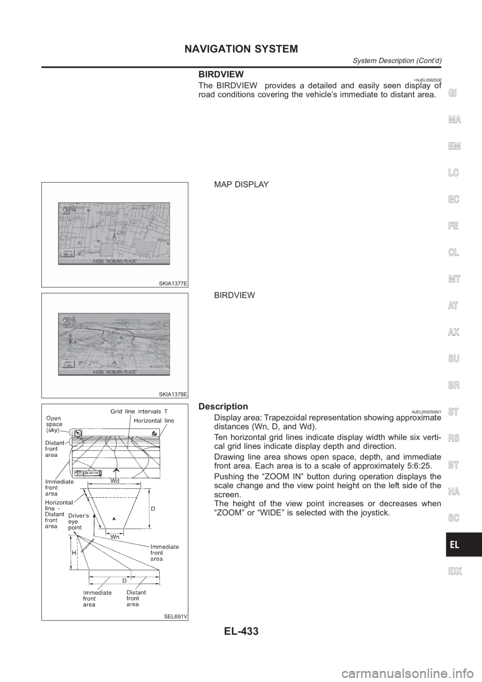
BIRDVIEW=NJEL0592S06The BIRDVIEW provides a detailed and easily seen display of
road conditions covering the vehicle’s immediate to distant area.
SKIA1377E
MAP DISPLAY
SKIA1378E
BIRDVIEW
SEL691V
DescriptionNJEL0592S0601Display area: Trapezoidal representation showing approximate
distances (Wn, D, and Wd).
Ten horizontal grid lines indicate display width while six verti-
cal grid lines indicate display depth and direction.
Drawing line area shows open space, depth, and immediate
front area. Each area is to a scale of approximately 5:6:25.
Pushing the “ZOOM IN” button during operation displays the
scale change and the view point height on the left side of the
screen.
The height of the view point increases or decreases when
“ZOOM” or “WIDE” is selected with the joystick.
GI
MA
EM
LC
EC
FE
CL
MT
AT
AX
SU
BR
ST
RS
BT
HA
SC
IDX
NAVIGATION SYSTEM
System Description (Cont’d)
EL-433
Page 2799 of 3189
SKIA1617E
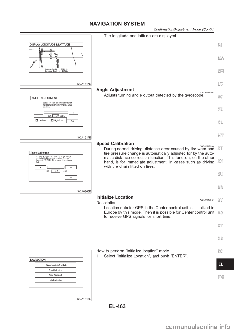
The longitude and latitude are displayed.
SKIA1517E
Angle AdjustmentNJEL0604S0402Adjusts turning angle output detected by the gyroscope.
SKIA0365E
Speed CalibrationNJEL0604S0403During normal driving, distance error caused by tire wear and
tire pressure change is automatically adjusted for by the auto-
matic distance correction function. This function, on the other
hand, is for immediate adjustment, in cases such as driving
with tire chain fitted on tires.
Initialize LocationNJEL0604S0404Description
Location data for GPS in the Center control unit is initialized in
Europe by this mode. Then it is possible for Center control unit
to receive GPS signals for short time.
SKIA1618E
How to perform “Initialize location” mode
1. Select “Initialize Location”, and push “ENTER”.
GI
MA
EM
LC
EC
FE
CL
MT
AT
AX
SU
BR
ST
RS
BT
HA
SC
IDX
NAVIGATION SYSTEM
Confirmation/Adjustment Mode (Cont’d)
EL-463
Page 2800 of 3189
SKIA1619E
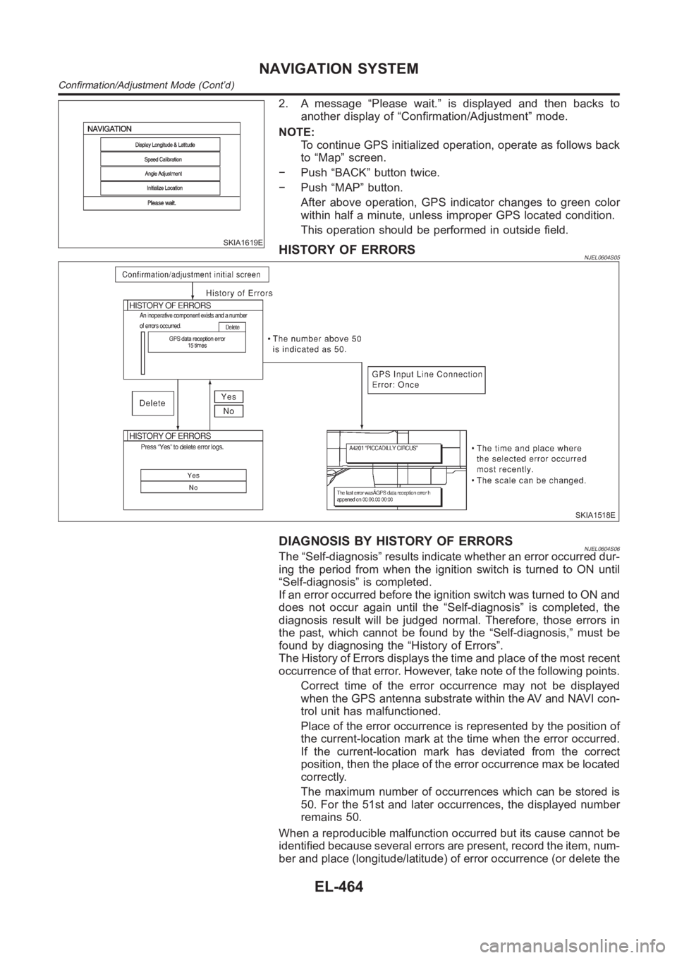
2. A message “Please wait.” is displayed and then backs to
another display of “Confirmation/Adjustment” mode.
NOTE:
To continue GPS initialized operation, operate as follows back
to “Map” screen.
− Push “BACK” button twice.
− Push “MAP” button.
After above operation, GPS indicator changes to green color
within half a minute, unless improper GPS located condition.
This operation should be performed in outside field.
HISTORY OF ERRORSNJEL0604S05
SKIA1518E
DIAGNOSIS BY HISTORY OF ERRORSNJEL0604S06The “Self-diagnosis” results indicate whether an error occurred dur-
ing the period from when the ignition switch is turned to ON until
“Self-diagnosis” is completed.
If an error occurred before the ignition switch was turned to ON and
does not occur again until the “Self-diagnosis” is completed, the
diagnosis result will be judged normal. Therefore, those errors in
the past, which cannot be found by the “Self-diagnosis,” must be
found by diagnosing the “History of Errors”.
The History of Errors displays the time and place of the most recent
occurrence of that error. However, take note of the following points.
Correct time of the error occurrence may not be displayed
when the GPS antenna substrate within the AV and NAVI con-
trol unit has malfunctioned.
Place of the error occurrence is represented by the position of
the current-location mark at the time when the error occurred.
If the current-location mark has deviated from the correct
position, then the place of the error occurrence max be located
correctly.
The maximum number of occurrences which can be stored is
50. For the 51st and later occurrences, the displayed number
remains 50.
When a reproducible malfunction occurred but its cause cannot be
identified because several errors are present, record the item, num-
ber and place (longitude/latitude) of error occurrence (or delete the
NAVIGATION SYSTEM
Confirmation/Adjustment Mode (Cont’d)
EL-464