2003 NISSAN ALMERA N16 iat
[x] Cancel search: iatPage 2836 of 3189
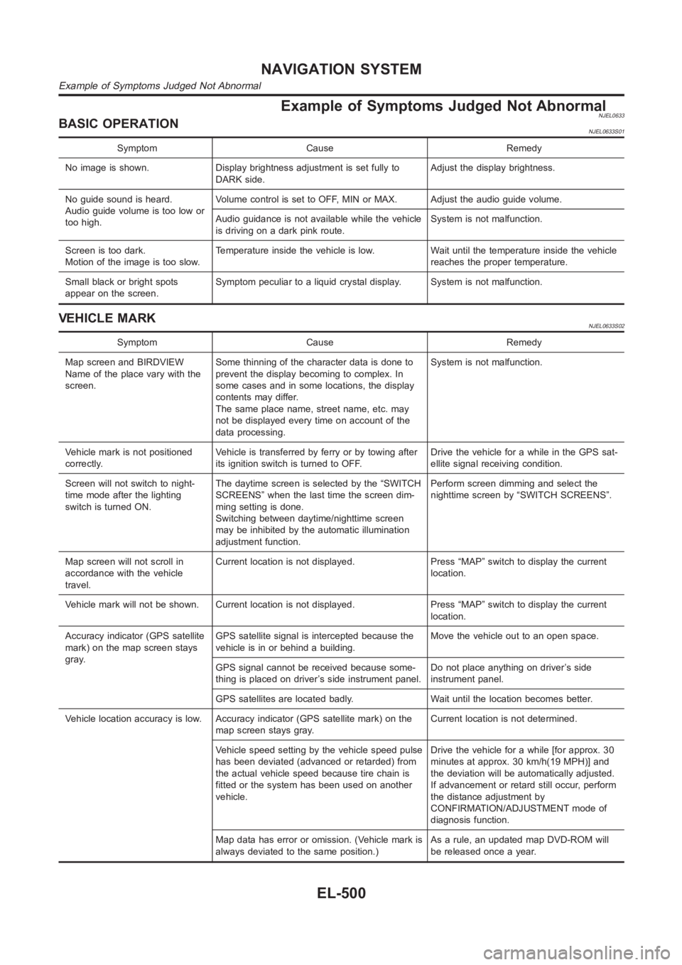
Example of Symptoms Judged Not AbnormalNJEL0633BASIC OPERATIONNJEL0633S01
Symptom Cause Remedy
No image is shown. Display brightness adjustment is set fully to
DARK side.Adjust the display brightness.
No guide sound is heard.
Audio guide volume is too low or
too high.Volume control is set to OFF, MIN or MAX. Adjust the audio guide volume.
Audio guidance is not available while the vehicle
is driving on a dark pink route.System is not malfunction.
Screen is too dark.
Motion of the image is too slow.Temperature inside the vehicle is low. Wait until the temperature inside the vehicle
reaches the proper temperature.
Small black or bright spots
appear on the screen.Symptom peculiar to a liquid crystal display. System is not malfunction.
VEHICLE MARKNJEL0633S02
Symptom Cause Remedy
Map screen and BIRDVIEW
Name of the place vary with the
screen.Some thinning of the character data is done to
prevent the display becoming to complex. In
some cases and in some locations, the display
contents may differ.
The same place name, street name, etc. may
not be displayed every time on account of the
data processing.System is not malfunction.
Vehicle mark is not positioned
correctly.Vehicle is transferred by ferry or by towing after
its ignition switch is turned to OFF.Drive the vehicle for a while in the GPS sat-
ellite signal receiving condition.
Screen will not switch to night-
time mode after the lighting
switch is turned ON.The daytime screen is selected by the “SWITCH
SCREENS” when the last time the screen dim-
ming setting is done.
Switching between daytime/nighttime screen
may be inhibited by the automatic illumination
adjustment function.Perform screen dimming and select the
nighttime screen by “SWITCH SCREENS”.
Map screen will not scroll in
accordance with the vehicle
travel.Current location is not displayed. Press “MAP” switch to display the current
location.
Vehicle mark will not be shown. Current location is not displayed. Press “MAP” switch to display the current
location.
Accuracy indicator (GPS satellite
mark) on the map screen stays
gray.GPS satellite signal is intercepted because the
vehicle is in or behind a building.Move the vehicle out to an open space.
GPS signal cannot be received because some-
thing is placed on driver’s side instrument panel.Do not place anything on driver’s side
instrument panel.
GPS satellites are located badly. Wait until the location becomes better.
Vehicle location accuracy is low. Accuracy indicator (GPS satellite mark)onthe
map screen stays gray.Current location is not determined.
Vehicle speed setting by the vehicle speed pulse
has been deviated (advanced or retarded) from
the actual vehicle speed because tire chain is
fitted or the system has been used on another
vehicle.Drive the vehicle for a while [for approx. 30
minutes at approx. 30 km/h(19 MPH)] and
the deviation will be automatically adjusted.
If advancement or retard still occur, perform
the distance adjustment by
CONFIRMATION/ADJUSTMENT mode of
diagnosis function.
Map data has error or omission. (Vehicle mark is
always deviated to the same position.)As a rule, an updated map DVD-ROM will
be released once a year.
NAVIGATION SYSTEM
Example of Symptoms Judged Not Abnormal
EL-500
Page 2840 of 3189
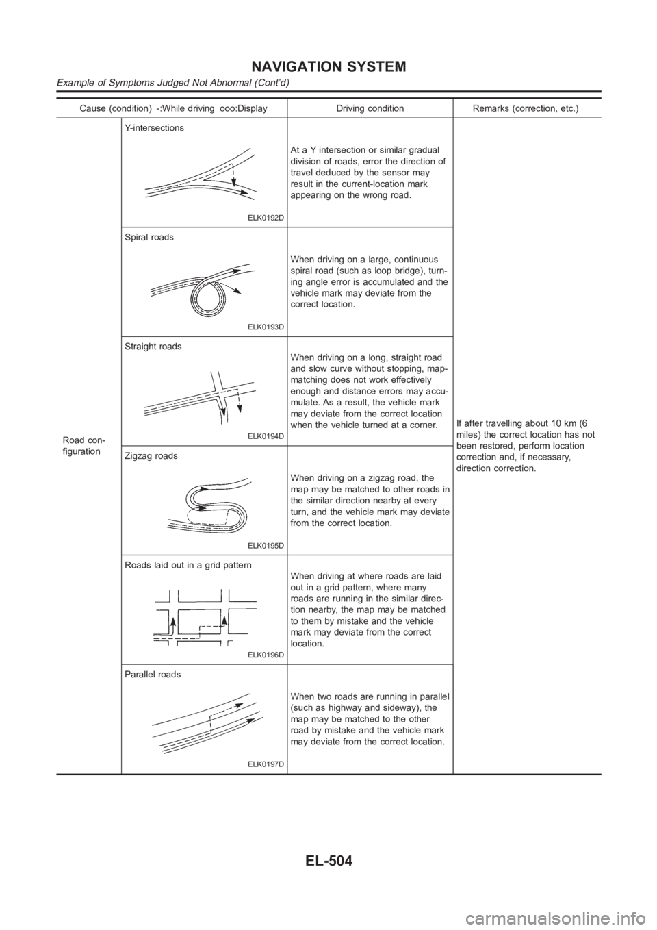
Cause (condition) -:While driving ooo:Display Driving condition Remarks (correction, etc.)
Road con-
figurationY-intersections
ELK0192D
At a Y intersection or similar gradual
division of roads, error the direction of
travel deduced by the sensor may
result in the current-location mark
appearing on the wrong road.
If after travelling about 10 km (6
miles) the correct location has not
been restored, perform location
correction and, if necessary,
direction correction. Spiral roads
ELK0193D
When driving on a large, continuous
spiral road (such as loop bridge), turn-
ing angle error is accumulated and the
vehicle mark may deviate from the
correct location.
Straight roads
ELK0194D
When driving on a long, straight road
and slow curve without stopping, map-
matching does not work effectively
enough and distance errors may accu-
mulate. As a result, the vehicle mark
may deviate from the correct location
when the vehicle turned at a corner.
Zigzag roads
ELK0195D
When driving on a zigzag road, the
map may be matched to other roads in
the similar direction nearby at every
turn, and the vehicle mark may deviate
from the correct location.
Roads laid out in a grid pattern
ELK0196D
When driving at where roads are laid
out in a grid pattern, where many
roads are running in the similar direc-
tion nearby, the map may be matched
to them by mistake and the vehicle
mark may deviate from the correct
location.
Parallel roads
ELK0197D
When two roads are running in parallel
(such as highway and sideway), the
map may be matched to the other
road by mistake and the vehicle mark
may deviate from the correct location.
NAVIGATION SYSTEM
Example of Symptoms Judged Not Abnormal (Cont’d)
EL-504
Page 2841 of 3189
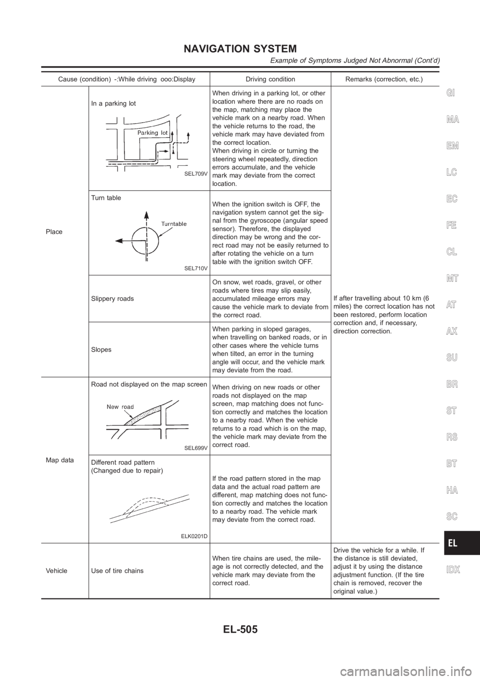
Cause (condition) -:While driving ooo:Display Driving condition Remarks (correction, etc.)
PlaceIn a parking lot
SEL709V
When driving in a parking lot, or other
location where there are no roads on
the map, matching may place the
vehicle mark on a nearby road. When
the vehicle returns to the road, the
vehicle mark may have deviated from
the correct location.
When driving in circle or turning the
steering wheel repeatedly, direction
errors accumulate, and the vehicle
mark may deviate from the correct
location.
If after travelling about 10 km (6
miles) the correct location has not
been restored, perform location
correction and, if necessary,
direction correction. Turn table
SEL710V
When the ignition switch is OFF, the
navigation system cannot get the sig-
nal from the gyroscope (angular speed
sensor). Therefore, the displayed
direction may be wrong and the cor-
rect road may not be easily returned to
after rotating the vehicle on a turn
table with the ignition switch OFF.
Slippery roadsOn snow, wet roads, gravel, or other
roads where tires may slip easily,
accumulated mileage errors may
cause the vehicle mark to deviate from
the correct road.
SlopesWhen parking in sloped garages,
when travelling on banked roads, or in
other cases where the vehicle turns
when tilted, an error in the turning
angle will occur, and the vehicle mark
may deviate from the road.
Map dataRoad not displayed on the map screen
SEL699V
When driving on new roads or other
roads not displayed on the map
screen, map matching does not func-
tion correctly and matches the location
to a nearby road. When the vehicle
returns to a road which is on the map,
the vehicle mark may deviate from the
correct road.
Different road pattern
(Changed due to repair)
ELK0201D
If the road pattern stored in the map
data and the actual road pattern are
different, map matching does not func-
tion correctly and matches the location
to a nearby road. The vehicle mark
may deviate from the correct road.
Vehicle Use of tire chainsWhen tire chains are used, the mile-
age is not correctly detected, and the
vehicle mark may deviate from the
correct road.Drive the vehicle for a while. If
the distance is still deviated,
adjust it by using the distance
adjustment function. (If the tire
chain is removed, recover the
original value.)
GI
MA
EM
LC
EC
FE
CL
MT
AT
AX
SU
BR
ST
RS
BT
HA
SC
IDX
NAVIGATION SYSTEM
Example of Symptoms Judged Not Abnormal (Cont’d)
EL-505
Page 2842 of 3189
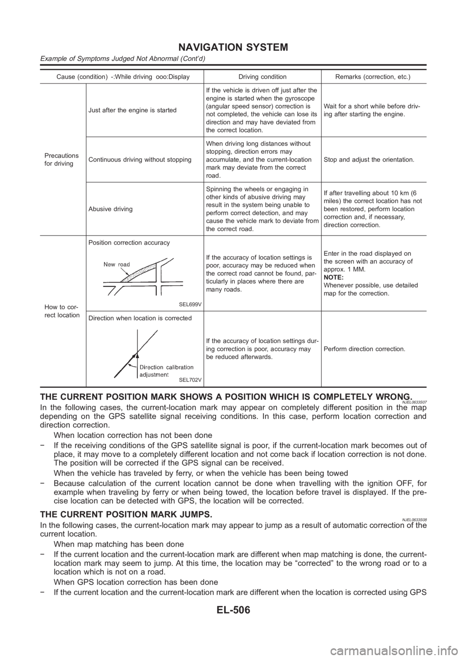
Cause (condition) -:While driving ooo:Display Driving condition Remarks (correction, etc.)
Precautions
for drivingJust after the engine is startedIf the vehicle is driven off just after the
engine is started when the gyroscope
(angular speed sensor) correction is
not completed, the vehicle can lose its
direction and may have deviated from
the correct location.Wait for a short while before driv-
ing after starting the engine.
Continuous driving without stoppingWhen driving long distances without
stopping, direction errors may
accumulate, and the current-location
mark may deviate from the correct
road.Stop and adjust the orientation.
Abusive drivingSpinning the wheels or engaging in
other kinds of abusive driving may
result in the system being unable to
perform correct detection, and may
cause the vehicle mark to deviate from
the correct road.If after travelling about 10 km (6
miles) the correct location has not
been restored, perform location
correction and, if necessary,
direction correction.
How to cor-
rect locationPosition correction accuracy
SEL699V
If the accuracy of location settings is
poor, accuracy may be reduced when
the correct road cannot be found, par-
ticularly in places where there are
many roads.Enter in the road displayed on
the screen with an accuracy of
approx. 1 MM.
NOTE:
Whenever possible, use detailed
map for the correction.
Direction when location is corrected
SEL702V
If the accuracy of location settings dur-
ing correction is poor, accuracy may
be reduced afterwards.Perform direction correction.
THE CURRENT POSITION MARK SHOWS A POSITION WHICH IS COMPLETELY WRONG.NJEL0633S07In the following cases, the current-location mark may appear on completely different position in the map
depending on the GPS satellite signal receiving conditions. In this case,perform location correction and
direction correction.
When location correction has not been done
− If the receiving conditions of the GPS satellite signal is poor, if the current-location mark becomes out of
place, it may move to a completely different location and not come back if location correction is not done.
The position will be corrected if the GPS signal can be received.
When the vehicle has traveled by ferry, or when the vehicle has been being towed
− Because calculation of the current location cannot be done when travelling with the ignition OFF, for
example when traveling by ferry or when being towed, the location before travel is displayed. If the pre-
cise location can be detected with GPS, the location will be corrected.
THE CURRENT POSITION MARK JUMPS.NJEL0633S08In the following cases, the current-location mark may appear to jump as a result of automatic correction of the
current location.
When map matching has been done
− If the current location and the current-location mark are different whenmap matching is done, the current-
location mark may seem to jump. At this time, the location may be “corrected” to the wrong road or to a
location which is not on a road.
When GPS location correction has been done
− If the current location and the current-location mark are different whenthe location is corrected using GPS
NAVIGATION SYSTEM
Example of Symptoms Judged Not Abnormal (Cont’d)
EL-506
Page 2843 of 3189
measurements, the current-location mark may seem to jump. At this time, the location may be “corrected”
to a location which is not on a road.
THE CURRENT LOCATION MARK IS IN A RIVER OR THE SEA.NJEL0633S09The navigation system moves the current location mark with no distinctionbetween land and rivers or sea. If
the location mark is somehow out of place, it may appear that the vehicle is driving in a river or the sea.
WHEN DRIVING ON THE SAME ROAD, SOMETIMES THE CURRENT-LOCATION MARK IS IN
THE RIGHT PLACE AND SOMETIMES IT IS THE WRONG PLACE.
NJEL0633S10The conditions of the GPS antenna (GPS data) and gyroscope (angular speed sensor) change gradually.
Depending on the road traveled and the operation of the steering wheel, thelocation detection results will be
different. Therefore, even on a road on which the location has never been wrong, conditions may cause the
vehicle mark to deviate.
LOCATION CORRECTION BY MAP MATCHING IS SLOW.NJEL0633S11The map matching function needs to refer to the data of the surrounding area. It is necessary to drive some
distance for the function to work.
Because map matching operates on this principle, when there are many roadsrunning in similar direc-
tions in the surrounding area, no matching determination may be made. The location may not be corrected
until some special feature is found.
ALTHOUGH THE GPS RECEIVING DISPLAY IS GREEN, THE VEHICLE MARK DOES NOT
RETURN TO THE CORRECT LOCATION.
NJEL0633S12The GPS accuracy has an error of about 10 m (30 ft). In some cases the current-location mark may not
be on the correct street, even when GPS location-correction is done.
The navigation system compares the results of GPS location detection withthe results from map-match-
ing location detection. The one which is determined to have higher accuracyisused.
GPS location correction may not be performed when the vehicle is stopped.
THE NAME OF THE CURRENT PLACE IS NOT DISPLAYED.NJEL0633S13The current place name may not be displayed if there are no place names displayed on the map screen.
CONTENTS OF THE DISPLAY DIFFER FOR THE BIRDVIEW AND THE (FLAT) MAP
SCREEN.
NJEL0633S14Difference of the BIRDVIEW Screen From the Flat Map Screen Are as Follows.NJEL0633S1401The current place name displays names which are primarily in the directionof vehicle travel.
The amount of time before the vehicle travel or turn angle is updated on the screen is longer than for the
(flat) map display.
The conditions for display of place names, roads, and other data are different for nearby areas and for
more distant areas.
Some thinning of the character data is done to prevent the display becomingto complex. In some cases
and in some locations, the display contents may differ.
The same place name, street name, etc. may be displayed multiple times.
GI
MA
EM
LC
EC
FE
CL
MT
AT
AX
SU
BR
ST
RS
BT
HA
SC
IDX
NAVIGATION SYSTEM
Example of Symptoms Judged Not Abnormal (Cont’d)
EL-507
Page 2935 of 3189
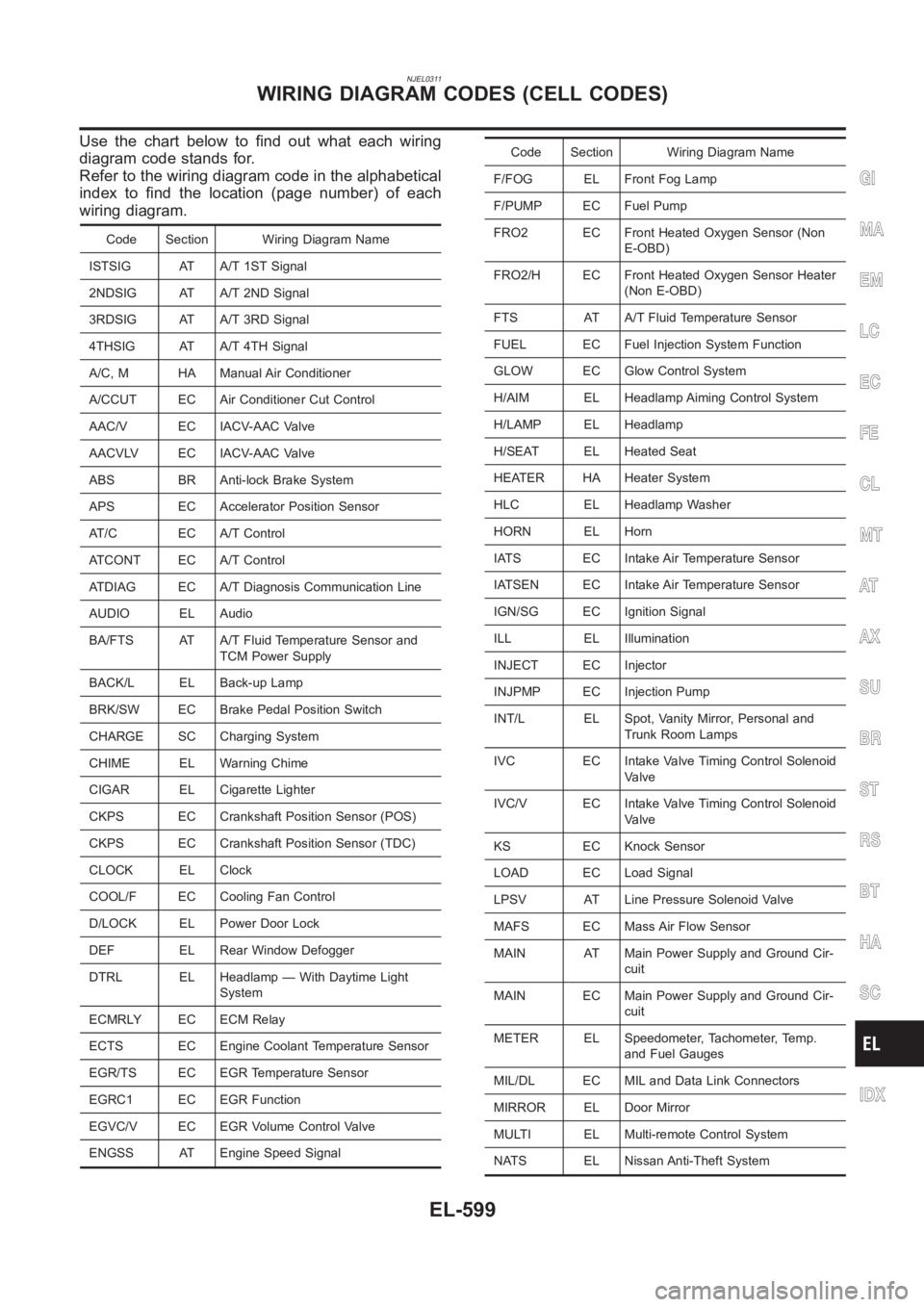
NJEL0311
Use the chart below to find out what each wiring
diagram code stands for.
Refer to the wiring diagram code in the alphabetical
index to find the location (page number) of each
wiring diagram.
Code Section Wiring Diagram Name
ISTSIG AT A/T 1ST Signal
2NDSIG AT A/T 2ND Signal
3RDSIG AT A/T 3RD Signal
4THSIG AT A/T 4TH Signal
A/C, M HA Manual Air Conditioner
A/CCUT EC Air Conditioner Cut Control
AAC/V EC IACV-AAC Valve
AACVLV EC IACV-AAC Valve
ABS BR Anti-lock Brake System
APS EC Accelerator Position Sensor
AT/C EC A/T Control
ATCONT EC A/T Control
ATDIAG EC A/T Diagnosis Communication Line
AUDIO EL Audio
BA/FTS AT A/T Fluid Temperature Sensor and
TCM Power Supply
BACK/L EL Back-up Lamp
BRK/SW EC Brake Pedal Position Switch
CHARGE SC Charging System
CHIME EL Warning Chime
CIGAR EL Cigarette Lighter
CKPS EC Crankshaft Position Sensor (POS)
CKPS EC Crankshaft Position Sensor (TDC)
CLOCK EL Clock
COOL/F EC Cooling Fan Control
D/LOCK EL Power Door Lock
DEF EL Rear Window Defogger
DTRL EL Headlamp — With Daytime Light
System
ECMRLY EC ECM Relay
ECTS EC Engine Coolant Temperature Sensor
EGR/TS EC EGR Temperature Sensor
EGRC1 EC EGR Function
EGVC/V EC EGR Volume Control Valve
ENGSS AT Engine Speed Signal
Code Section Wiring Diagram Name
F/FOG EL Front Fog Lamp
F/PUMP EC Fuel Pump
FRO2 EC Front Heated Oxygen Sensor (Non
E-OBD)
FRO2/H EC Front Heated Oxygen Sensor Heater
(Non E-OBD)
FTS AT A/T Fluid Temperature Sensor
FUEL EC Fuel Injection System Function
GLOW EC Glow Control System
H/AIM EL Headlamp Aiming Control System
H/LAMP EL Headlamp
H/SEAT EL Heated Seat
HEATER HA Heater System
HLC EL Headlamp Washer
HORN EL Horn
IATS EC Intake Air Temperature Sensor
IATSEN EC Intake Air Temperature Sensor
IGN/SG EC Ignition Signal
ILL EL Illumination
INJECT EC Injector
INJPMP EC Injection Pump
INT/L EL Spot, Vanity Mirror, Personal and
Trunk Room Lamps
IVC EC Intake Valve Timing Control Solenoid
Valve
IVC/V EC Intake Valve Timing Control Solenoid
Valve
KS EC Knock Sensor
LOAD EC Load Signal
LPSV AT Line Pressure Solenoid Valve
MAFS EC Mass Air Flow Sensor
MAIN AT Main Power Supply and Ground Cir-
cuit
MAIN EC Main Power Supply and Ground Cir-
cuit
METER EL Speedometer, Tachometer, Temp.
and Fuel Gauges
MIL/DL EC MIL and Data Link Connectors
MIRROR EL Door Mirror
MULTI EL Multi-remote Control System
NATS EL Nissan Anti-Theft System
GI
MA
EM
LC
EC
FE
CL
MT
AT
AX
SU
BR
ST
RS
BT
HA
SC
IDX
WIRING DIAGRAM CODES (CELL CODES)
EL-599
Page 2938 of 3189
Supplemental Restraint System (SRS) “AIR
BAG” and “SEAT BELT PRE-TENSIONER”
NJHA0190The Supplemental Restraint System such as “AIR BAG” and “SEAT BELT PRE-TENSIONER” used along with
a seat belt, helps to reduce the risk or severity of injury to the driver and front passenger for certain types of
collision. The SRS system composition which is available to NISSAN MODEL N16 is as follows (The compo-
sition varies according to the destination and optional equipment.):
For a frontal collision
The Supplemental Restraint System consists of driver air bag module (located in the center of the steer-
ing wheel), front passenger air bag module (located on the instrument panel on passenger side), front seat
belt pre-tensioners, a diagnosis sensor unit, warning lamp, wiring harness and spiral cable.
For a side collision
The Supplemental Restraint System consists of front side air bag module (located in the outer side of front
seat), side air bag (satellite) sensor, diagnosis sensor unit (one of components of air bags for a frontal
collision), wiring harness, warning lamp (one of components of air bags for a frontal collision).
Information necessary to service the system safely is included in theRS sectionof this Service Manual.
WARNING:
To avoid rendering the SRS inoperative, which could increase the risk of personal injury or death
in the event of a collision which would result in air bag inflation, all maintenance should be per-
formed by an authorized NISSAN dealer.
Improper maintenance, including incorrect removal and installation of the SRS, can lead to per-
sonal injury caused by unintentional activation of the system. For removalofSpiralCableandAir
Bag Module, see the RS section.
Do not use electrical test equipment on any circuit related to the SRS unless instructed to in this
Service Manual. Spiral cable and wiring harnesses covered with yellow and/or orange insulation
tape either just before the harness connectors or for the complete harnessare related to the SRS.
Precautions for Working with HFC-134a
(R-134a)
NJHA0113WARNING:
CFC-12 (R-12) refrigerant and HFC-134a (R-134a) refrigerant are not compatible. These refrigerants
must never be mixed, even in the smallest amounts. If the refrigerants are mixed, compressor
malfunction is likely to occur.
Use only specified lubricant for the HFC-134a (R-134a) A/C system and HFC-134a (R-134a) compo-
nents. If lubricant other than that specified is used, compressor malfunction is likely to occur.
The specified HFC-134a (R-134a) lubricant rapidly absorbs moisture fromthe atmosphere. The fol-
lowing handling precautions must be observed:
a) When removing refrigerant components from a vehicle, immediately cap (seal) the component to
minimize the entry of moisture from the atmosphere.
b) When installing refrigerant components to a vehicle, do not remove the caps (unseal) until just
before connecting the components. Connect all refrigerant loop components as quickly as pos-
sible to minimize the entry of moisture into system.
c) Only use the specified lubricant from a sealed container. Immediately reseal containers of lubri-
cant. Without proper sealing, lubricant will become moisture saturated and should not be used.
d) Avoid breathing A/C refrigerant and lubricant vapor or mist. Exposure may irritate eyes, nose and
throat. Remove HFC-134a (R-134a) from the A/C system, using certified service equipment meet-
ing requirements of HFC-134a (R-134a) recycling equipment, or HFC-134a (R-134a) recovery equip-
ment. If accidental system discharge occurs, ventilate work area before resuming service. Addi-
tional health and safety information may be obtained from refrigerant andlubricant manufactur-
ers.
e) Do not allow lubricant (Nissan A/C System Oil Type S) to come in contact with styrofoam parts.
Damage may result.
General Refrigerant PrecautionsNJHA0114WARNING:
Do not release refrigerant into the air. Use approved recovery/recyclingequipment to capture the
refrigerant every time an air conditioning system is discharged.
PRECAUTIONSMANUAL
Supplemental Restraint System (SRS) “AIR BAG” and “SEAT BELT PRE-TENSIONER”
HA-2
Page 2940 of 3189
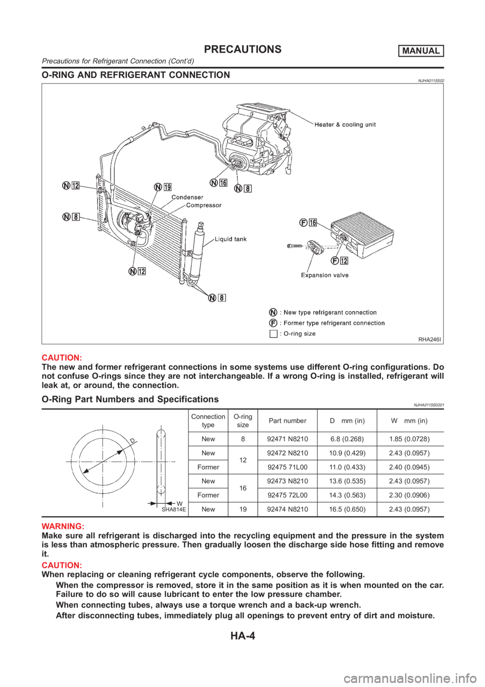
O-RING AND REFRIGERANT CONNECTIONNJHA0115S02
RHA246I
CAUTION:
The new and former refrigerant connections in some systems use different O-ring configurations. Do
not confuse O-rings since they are not interchangeable. If a wrong O-ring is installed, refrigerant will
leak at, or around, the connection.
O-Ring Part Numbers and SpecificationsNJHA0115S0201
SHA814E
Connection
typeO-ring
sizePart number D mm (in) W mm (in)
New 8 92471 N8210 6.8 (0.268) 1.85 (0.0728)
New
1292472 N8210 10.9 (0.429) 2.43 (0.0957)
Former 92475 71L00 11.0 (0.433) 2.40 (0.0945)
New
1692473 N8210 13.6 (0.535) 2.43 (0.0957)
Former 92475 72L00 14.3 (0.563) 2.30 (0.0906)
New 19 92474 N8210 16.5 (0.650) 2.43 (0.0957)
WARNING:
Make sure all refrigerant is discharged into the recycling equipment and the pressure in the system
is less than atmospheric pressure. Then gradually loosen the discharge side hose fitting and remove
it.
CAUTION:
When replacing or cleaning refrigerant cycle components, observe the following.
When the compressor is removed, store it in the same position as it is when mounted on the car.
Failure to do so will cause lubricant to enter the low pressure chamber.
When connecting tubes, always use a torque wrench and a back-up wrench.
After disconnecting tubes, immediately plug all openings to prevent entry of dirt and moisture.
PRECAUTIONSMANUAL
Precautions for Refrigerant Connection (Cont’d)
HA-4