2003 NISSAN ALMERA N16 iat
[x] Cancel search: iatPage 2204 of 3189
SBR002A
SBR365AA
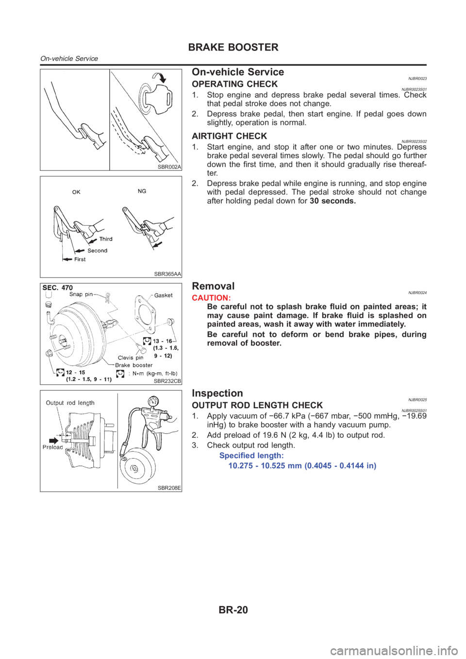
On-vehicle ServiceNJBR0023OPERATING CHECKNJBR0023S011. Stop engine and depress brake pedal several times. Check
that pedal stroke does not change.
2. Depress brake pedal, then start engine. If pedal goes down
slightly, operation is normal.
AIRTIGHT CHECKNJBR0023S021. Start engine, and stop it after one or two minutes. Depress
brake pedal several times slowly. The pedal should go further
down the first time, and then it should gradually rise thereaf-
ter.
2. Depress brake pedal while engine is running, and stop engine
with pedal depressed. The pedal stroke should not change
after holding pedal down for30 seconds.
SBR232CB
RemovalNJBR0024CAUTION:
Be careful not to splash brake fluid on painted areas; it
may cause paint damage. If brake fluid is splashed on
painted areas, wash it away with water immediately.
Be careful not to deform or bend brake pipes, during
removal of booster.
SBR208E
InspectionNJBR0025OUTPUT ROD LENGTH CHECKNJBR0025S011. Apply vacuum of −66.7 kPa (−667 mbar, −500 mmHg, −19.69
inHg) to brake booster with a handy vacuum pump.
2. Add preload of 19.6 N (2 kg, 4.4 lb) to output rod.
3. Check output rod length.
Specified length:
10.275 - 10.525 mm (0.4045 - 0.4144 in)
BRAKE BOOSTER
On-vehicle Service
BR-20
Page 2213 of 3189
CAUTION:
Use brake fluid to clean. Never use mineral oil.
PistonNJBR0033S0102CAUTION:
Piston sliding surface is plated. Do not polish with emery
paper even if rust or foreign materials are stuck to sliding
surface.
Check piston for score, rust, wear, damage or presence of foreign
materials. Replace if any of the above conditions are observed.
Slide Pin, Pin Bolt and Pin BootNJBR0033S0103Check for wear, cracks or other damage. Replace if any of the
above conditions are observed.
ROTORNJBR0033S02Rubbing SurfaceNJBR0033S0201Check rotor for roughness, cracks or chips.
SBR219C
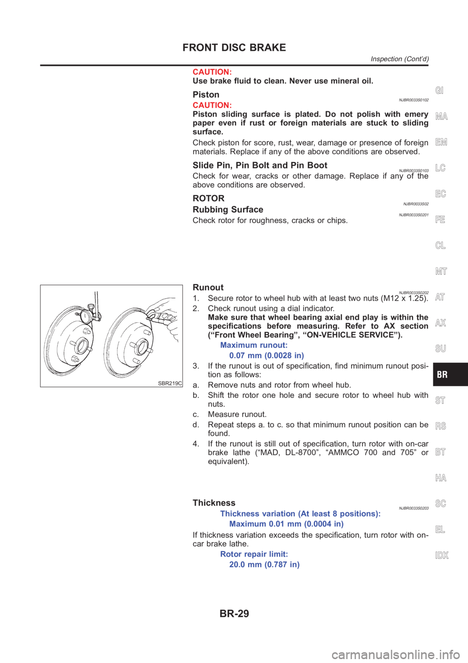
RunoutNJBR0033S02021. Secure rotor to wheel hub with at least two nuts (M12 x 1.25).
2. Check runout using a dial indicator.
Make sure that wheel bearing axial end play is within the
specifications before measuring. Refer to AX section
(“Front Wheel Bearing”, “ON-VEHICLE SERVICE”).
Maximum runout:
0.07 mm (0.0028 in)
3. If the runout is out of specification, find minimum runout posi-
tion as follows:
a. Remove nuts and rotor from wheel hub.
b. Shift the rotor one hole and secure rotor to wheel hub with
nuts.
c. Measure runout.
d. Repeat steps a. to c. so that minimum runout position can be
found.
4. If the runout is still out of specification, turn rotor with on-car
brake lathe (“MAD, DL-8700”, “AMMCO 700 and 705” or
equivalent).
ThicknessNJBR0033S0203Thickness variation (At least 8 positions):
Maximum 0.01 mm (0.0004 in)
If thickness variation exceeds the specification, turn rotor with on-
car brake lathe.
Rotor repair limit:
20.0 mm (0.787 in)
GI
MA
EM
LC
EC
FE
CL
MT
AT
AX
SU
ST
RS
BT
HA
SC
EL
IDX
FRONT DISC BRAKE
Inspection (Cont’d)
BR-29
Page 2219 of 3189
Pin and Pin BootNJBR0041S0104Check for wear, cracks or other damage.
Replace if any of the above conditions are observed.
SBR219C
ROTORNJBR0041S02Rubbing SurfaceNJBR0041S0201Check rotor for roughness, cracks or chips.
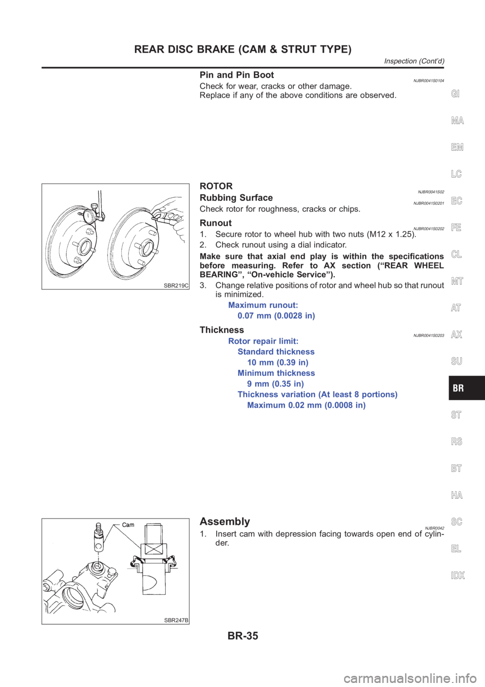
RunoutNJBR0041S02021. Secure rotor to wheel hub with two nuts (M12 x 1.25).
2. Check runout using a dial indicator.
Make sure that axial end play is within the specifications
before measuring. Refer to AX section (“REAR WHEEL
BEARING”, “On-vehicle Service”).
3. Change relative positions of rotor and wheel hub so that runout
is minimized.
Maximum runout:
0.07 mm (0.0028 in)
ThicknessNJBR0041S0203Rotor repair limit:
Standard thickness
10 mm (0.39 in)
Minimum thickness
9 mm (0.35 in)
Thickness variation (At least 8 portions)
Maximum 0.02 mm (0.0008 in)
SBR247B
AssemblyNJBR00421. Insert cam with depression facing towards open end of cylin-
der.
GI
MA
EM
LC
EC
FE
CL
MT
AT
AX
SU
ST
RS
BT
HA
SC
EL
IDX
REAR DISC BRAKE (CAM & STRUT TYPE)
Inspection (Cont’d)
BR-35
Page 2226 of 3189
SBR219C
ROTORNJBR0145S02Rubbing SurfaceNJBR0145S0201Check rotor for roughness, cracks or chips.
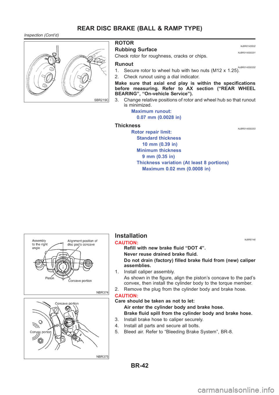
RunoutNJBR0145S02021. Secure rotor to wheel hub with two nuts (M12 x 1.25).
2. Check runout using a dial indicator.
Make sure that axial end play is within the specifications
before measuring. Refer to AX section (“REAR WHEEL
BEARING”, “On-vehicle Service”).
3. Change relative positions of rotor and wheel hub so that runout
is minimized.
Maximum runout:
0.07 mm (0.0028 in)
ThicknessNJBR0145S0203Rotor repair limit:
Standard thickness
10 mm (0.39 in)
Minimum thickness
9 mm (0.35 in)
Thickness variation (At least 8 portions)
Maximum 0.02 mm (0.0008 in)
NBR374
NBR375
InstallationNJBR0146CAUTION:
Refill with new brake fluid “DOT 4”.
Never reuse drained brake fluid.
Do not drain (factory) filled brake fluid from (new) caliper
assemblies.
1. Install caliper assembly.
As shown in the figure, align the piston’s concave to the pad’s
convex, then install the cylinder body to the torque member.
2. Remove the plug from the cylinder body and brake hose.
CAUTION:
Care should be taken as not to let:
Air enter the cylinder body and brake hose.
Brake fluid spill from the cylinder body and brake hose.
3. Install brake hose to caliper securely.
4. Install all parts and secure all bolts.
5. Bleed air. Refer to “Bleeding Brake System”, BR-8.
REAR DISC BRAKE (BALL & RAMP TYPE)
Inspection (Cont’d)
BR-42
Page 2265 of 3189
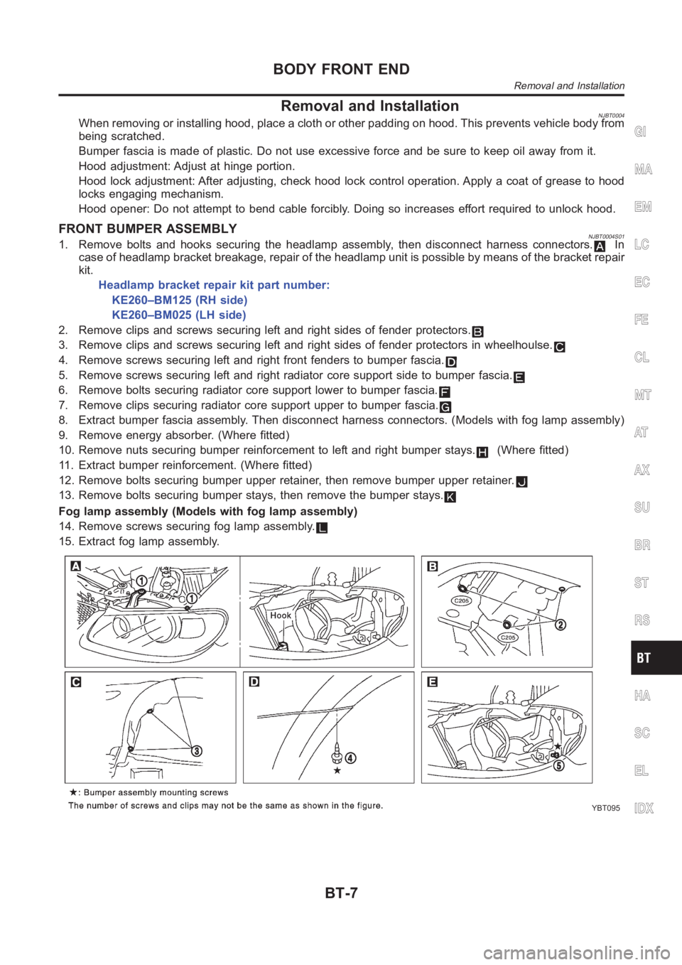
Removal and InstallationNJBT0004When removing or installing hood, place a cloth or other padding on hood. This prevents vehicle body from
being scratched.
Bumper fascia is made of plastic. Do not use excessive force and be sure to keep oil away from it.
Hood adjustment: Adjust at hinge portion.
Hood lock adjustment: After adjusting, check hood lock control operation. Apply a coat of grease to hood
locks engaging mechanism.
Hood opener: Do not attempt to bend cable forcibly. Doing so increases effort required to unlock hood.
FRONT BUMPER ASSEMBLYNJBT0004S011. Remove bolts and hooks securing the headlamp assembly, then disconnectharness connectors.In
case of headlamp bracket breakage, repair of the headlamp unit is possibleby means of the bracket repair
kit.
Headlamp bracket repair kit part number:
KE260–BM125 (RH side)
KE260–BM025 (LH side)
2. Remove clips and screws securing left and right sides of fender protectors.
3. Remove clips and screws securing left and right sides of fender protectors in wheelhoulse.
4. Remove screws securing left and right front fenders to bumper fascia.
5. Remove screws securing left and right radiator core support side to bumper fascia.
6. Remove bolts securing radiator core support lower to bumper fascia.
7. Remove clips securing radiator core support upper to bumper fascia.
8. Extract bumper fascia assembly. Then disconnect harness connectors. (Models with fog lamp assembly)
9. Remove energy absorber. (Where fitted)
10. Remove nuts securing bumper reinforcement to left and right bumper stays.
(Where fitted)
11. Extract bumper reinforcement. (Where fitted)
12. Remove bolts securing bumper upper retainer, then remove bumper upperretainer.
13. Remove bolts securing bumper stays, then remove the bumper stays.
Fog lamp assembly (Models with fog lamp assembly)
14. Remove screws securing fog lamp assembly.
15. Extract fog lamp assembly.
YBT095
GI
MA
EM
LC
EC
FE
CL
MT
AT
AX
SU
BR
ST
RS
HA
SC
EL
IDX
BODY FRONT END
Removal and Installation
BT-7
Page 2326 of 3189
SBF034BA
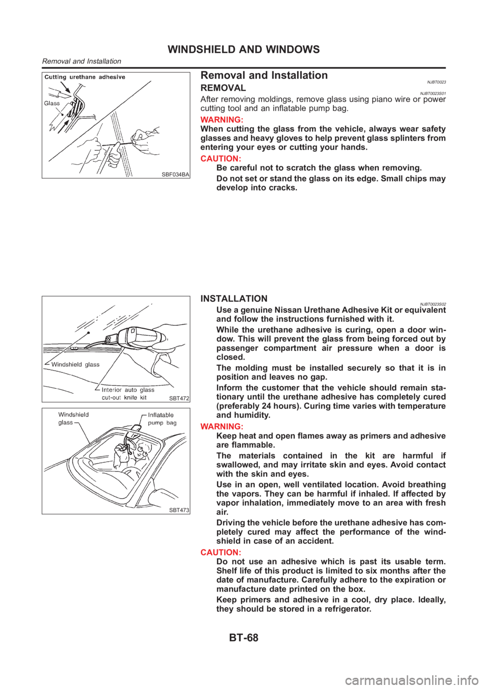
Removal and InstallationNJBT0023REMOVALNJBT0023S01After removing moldings, remove glass using piano wire or power
cutting tool and an inflatable pump bag.
WARNING:
When cutting the glass from the vehicle, always wear safety
glasses and heavy gloves to help prevent glass splinters from
entering your eyes or cutting your hands.
CAUTION:
Be careful not to scratch the glass when removing.
Do not set or stand the glass on its edge. Small chips may
develop into cracks.
SBT472
SBT473
INSTALLATIONNJBT0023S02Use a genuine Nissan Urethane Adhesive Kit or equivalent
and follow the instructions furnished with it.
While the urethane adhesive is curing, open a door win-
dow. This will prevent the glass from being forced out by
passenger compartment air pressure when a door is
closed.
The molding must be installed securely so that it is in
position and leaves no gap.
Inform the customer that the vehicle should remain sta-
tionary until the urethane adhesive has completely cured
(preferably 24 hours). Curing time varies with temperature
and humidity.
WARNING:
Keep heat and open flames away as primers and adhesive
are flammable.
The materials contained in the kit are harmful if
swallowed, and may irritate skin and eyes. Avoid contact
with the skin and eyes.
Use in an open, well ventilated location. Avoid breathing
the vapors. They can be harmful if inhaled. If affected by
vapor inhalation, immediately move to an area with fresh
air.
Driving the vehicle before the urethane adhesive has com-
pletely cured may affect the performance of the wind-
shield in case of an accident.
CAUTION:
Do not use an adhesive which is past its usable term.
Shelf life of this product is limited to six months after the
date of manufacture. Carefully adhere to the expiration or
manufacture date printed on the box.
Keep primers and adhesive in a cool, dry place. Ideally,
they should be stored in a refrigerator.
WINDSHIELD AND WINDOWS
Removal and Installation
BT-68
Page 2454 of 3189
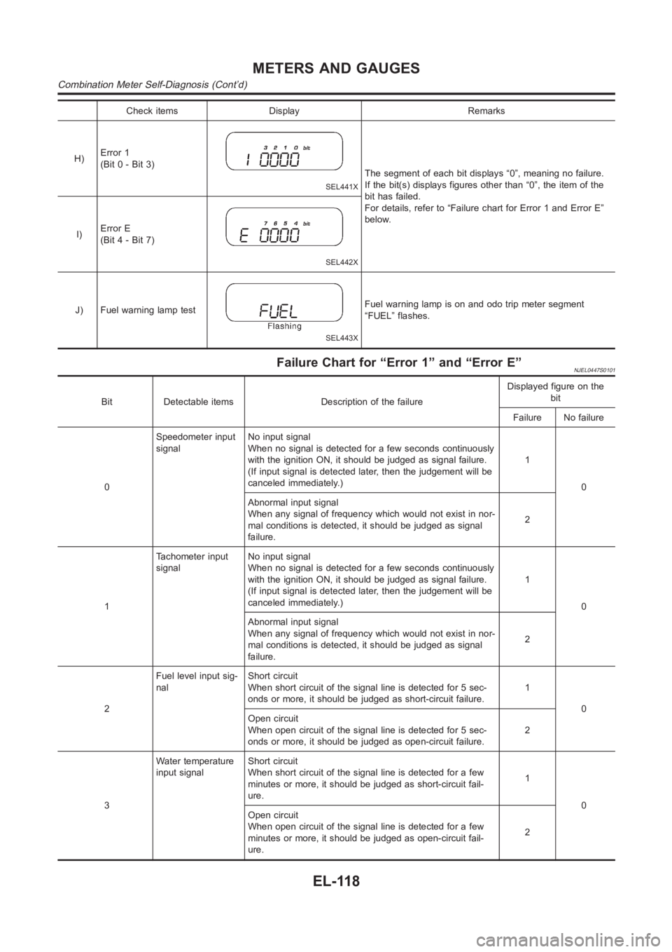
Check items Display Remarks
H)Error 1
(Bit 0 - Bit 3)
SEL441X
The segment of each bit displays “0”, meaning no failure.
If the bit(s) displays figures other than “0”, the item of the
bit has failed.
For details, refer to “Failure chart for Error 1 and Error E”
below.
I)Error E
(Bit 4 - Bit 7)
SEL442X
J) Fuel warning lamp test
SEL443X
Fuel warning lamp is on and odo trip meter segment
“FUEL” flashes.
Failure Chart for “Error 1” and “Error E”NJEL0447S0101
Bit Detectable items Description of the failureDisplayed figure on the
bit
Failure No failure
0Speedometer input
signalNo input signal
When no signal is detected for a few seconds continuously
with the ignition ON, it should be judged as signal failure.
(If input signal is detected later, then the judgement will be
canceled immediately.)1
0
Abnormal input signal
When any signal of frequency which would not exist in nor-
mal conditions is detected, it should be judged as signal
failure.2
1Tachometer input
signalNo input signal
When no signal is detected for a few seconds continuously
with the ignition ON, it should be judged as signal failure.
(If input signal is detected later, then the judgement will be
canceled immediately.)1
0
Abnormal input signal
When any signal of frequency which would not exist in nor-
mal conditions is detected, it should be judged as signal
failure.2
2Fuel level input sig-
nalShort circuit
When short circuit of the signal line is detected for 5 sec-
onds or more, it should be judged as short-circuit failure.1
0
Open circuit
When open circuit of the signal line is detected for 5 sec-
onds or more, it should be judged as open-circuit failure.2
3Water temperature
input signalShort circuit
When short circuit of the signal line is detected for a few
minutes or more, it should be judged as short-circuit fail-
ure.1
0
Open circuit
When open circuit of the signal line is detected for a few
minutes or more, it should be judged as open-circuit fail-
ure.2
METERS AND GAUGES
Combination Meter Self-Diagnosis (Cont’d)
EL-118
Page 2498 of 3189
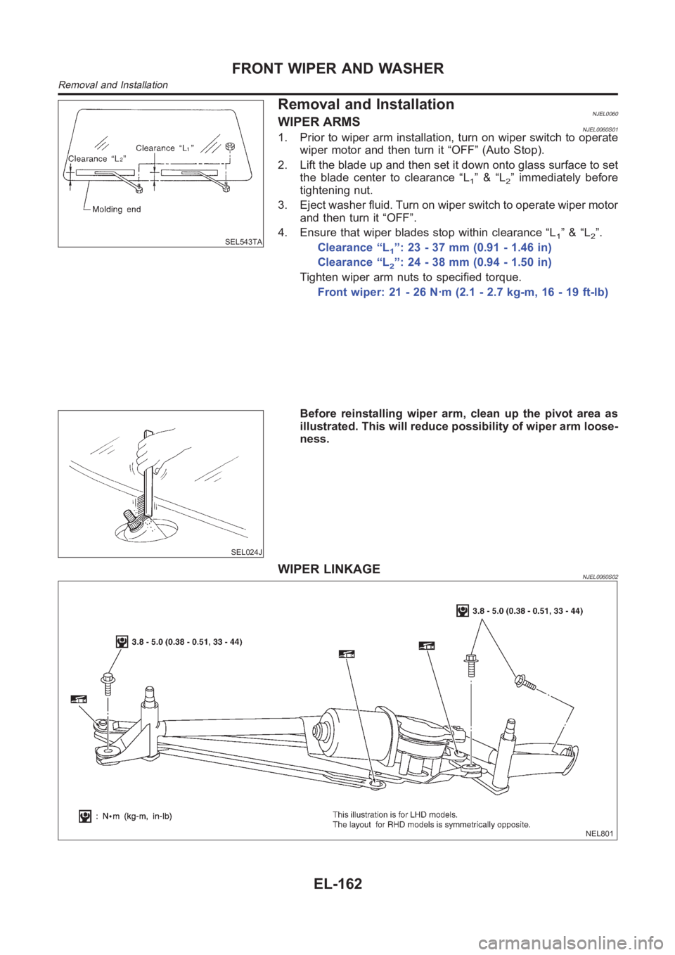
SEL543TA
Removal and InstallationNJEL0060WIPER ARMSNJEL0060S011. Prior to wiper arm installation, turn on wiper switch to operate
wiper motor and then turn it “OFF” (Auto Stop).
2. Lift the blade up and then set it down onto glass surface to set
the blade center to clearance “L
1”&“L2” immediately before
tightening nut.
3. Eject washer fluid. Turn on wiper switch to operate wiper motor
and then turn it “OFF”.
4. Ensure that wiper blades stop within clearance “L
1”&“L2”.
Clearance “L1”:23-37mm(0.91-1.46in)
Clearance “L
2”:24-38mm(0.94-1.50in)
Tighten wiper arm nuts to specified torque.
Front wiper: 21 - 26 N·m (2.1 - 2.7 kg-m, 16 - 19 ft-lb)
SEL024J
Before reinstalling wiper arm, clean up the pivot area as
illustrated. This will reduce possibility of wiper arm loose-
ness.
WIPER LINKAGENJEL0060S02
NEL801
FRONT WIPER AND WASHER
Removal and Installation
EL-162