Page 3023 of 3189
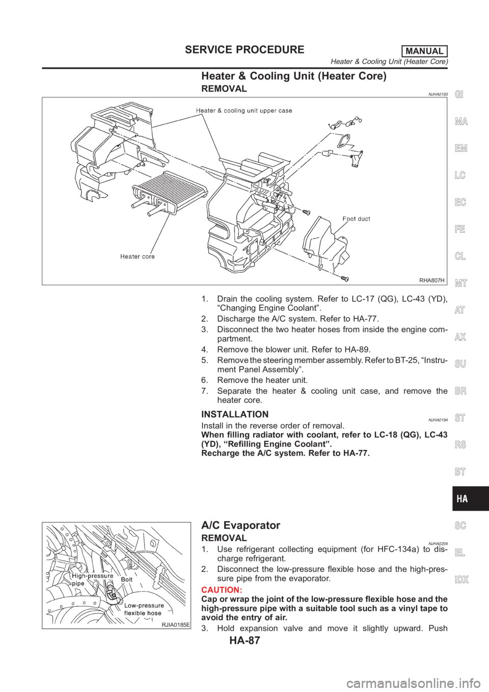
Heater & Cooling Unit (Heater Core)
REMOVALNJHA0193
RHA807H
1. Drain the cooling system. Refer to LC-17 (QG), LC-43 (YD),
“Changing Engine Coolant”.
2. Discharge the A/C system. Refer to HA-77.
3. Disconnect the two heater hoses from inside the engine com-
partment.
4. Remove the blower unit. Refer to HA-89.
5. Remove the steering member assembly. Refer to BT-25, “Instru-
ment Panel Assembly”.
6. Remove the heater unit.
7. Separate the heater & cooling unit case, and remove the
heater core.
INSTALLATIONNJHA0194Install in the reverse order of removal.
When filling radiator with coolant, refer to LC-18 (QG), LC-43
(YD), “Refilling Engine Coolant”.
Recharge the A/C system. Refer to HA-77.
RJIA0185E
A/C Evaporator
REMOVALNJHA02041. Use refrigerant collecting equipment (for HFC-134a) to dis-
charge refrigerant.
2. Disconnect the low-pressure flexible hose and the high-pres-
sure pipe from the evaporator.
CAUTION:
Cap or wrap the joint of the low-pressure flexible hose and the
high-pressure pipe with a suitable tool such as a vinyl tape to
avoid the entry of air.
3. Hold expansion valve and move it slightly upward. Push
GI
MA
EM
LC
EC
FE
CL
MT
AT
AX
SU
BR
ST
RS
BT
SC
EL
IDX
SERVICE PROCEDUREMANUAL
Heater & Cooling Unit (Heater Core)
HA-87
Page 3030 of 3189
5. If a leak detector detects a leak, verify at least once by blow-
ing compressed air into area of suspected leak, then repeat
check as outlined above.
6. Do not stop when one leak is found. Continue to check for
additional leaks at all system components.
If no leaks are found, perform steps 7 - 10.
7. Start engine.
8. Set the heater A/C control as follows:
1) A/C switch ON.
2) Face mode
3) Recirculation position
4) Max cold temperature
5) Fan speed high
9. Run engine at 1,500 rpm for at least 2 minutes.
10. Turn engine off and perform leak check again following steps
4 through 6 above.
SHA839E
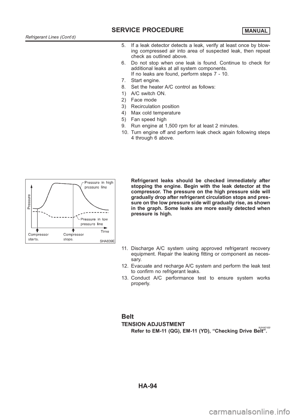
Refrigerant leaks should be checked immediately after
stopping the engine. Begin with the leak detector at the
compressor. The pressure on the high pressure side will
gradually drop after refrigerant circulation stops and pres-
sure on the low pressure side will gradually rise, as shown
in the graph. Some leaks are more easily detected when
pressure is high.
11. Discharge A/C system using approved refrigerant recovery
equipment. Repair the leaking fitting or component as neces-
sary.
12. Evacuate and recharge A/C system and perform the leak test
to confirm no refrigerant leaks.
13. Conduct A/C performance test to ensure system works
properly.
Belt
TENSION ADJUSTMENTNJHA0169Refer to EM-11 (QG), EM-11 (YD), “Checking Drive Belt”.
SERVICE PROCEDUREMANUAL
Refrigerant Lines (Cont’d)
HA-94
Page 3055 of 3189
SRS444
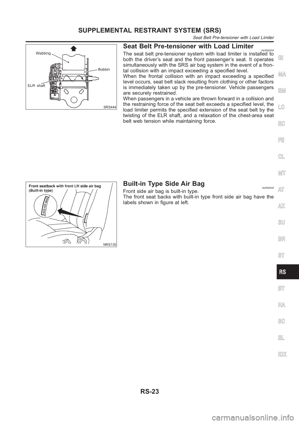
Seat Belt Pre-tensioner with Load Limiter=NJRS0034The seat belt pre-tensioner system with load limiter is installed to
both the driver’s seat and the front passenger’s seat. It operates
simultaneously with the SRS air bag system in the event of a fron-
tal collision with an impact exceeding a specified level.
When the frontal collision with an impact exceeding a specified
level occurs, seat belt slack resulting from clothing or other factors
is immediately taken up by the pre-tensioner. Vehicle passengers
are securely restrained.
When passengers in a vehicle are thrown forward in a collision and
the restraining force of the seat belt exceeds a specified level, the
load limiter permits the specified extension of the seat belt by the
twisting of the ELR shaft, and a relaxation of the chest-area seat
belt web tension while maintaining force.
NRS135
Built-in Type Side Air BagNJRS0035Front side air bag is built-in type.
The front seat backs with built-in type front side air bag have the
labels shown in figure at left.
GI
MA
EM
LC
EC
FE
CL
MT
AT
AX
SU
BR
ST
BT
HA
SC
EL
IDX
SUPPLEMENTAL RESTRAINT SYSTEM (SRS)
Seat Belt Pre-tensioner with Load Limiter
RS-23
Page 3057 of 3189
SRS797-A
Maintenance ItemsNJRS0012CAUTION:
Do not use electrical test equipment to check SRS circuit.
1. Check operation of “AIR BAG” warning lamp.
After turning ignition key to “ON” position, “AIR BAG” warning
lamp illuminates. The “AIR BAG” warning lamp will go off after
about 7 seconds if no malfunction is detected. If any of the fol-
lowing “AIR BAG” warning lamp conditions occur, immediately
check the air bag system. Refer to RS-49 for details.
The “AIR BAG” warning lamp does not illuminate when the
ignition switch is turned “ON”.
The “AIR BAG” warning lamp does not go off about 7 seconds
after the ignition switch is turned “ON”.
The “AIR BAG” warning lamp blinks after about 7 seconds after
the ignition switch is turned “ON”.
2. Visually check SRS components.
1) Diagnosis sensor unit
Check diagnosis sensor unit and bracket for dents, cracks and
deformities.
Check connectors for damage, and terminals for deformities.
2) Air bag module and steering wheel
Remove air bag module from steering wheel, instrument panel
or seatback. Check harness cover and connectors for damage,
terminals for deformities, and harness for binding.
Install driver air bag module to steering wheel to check fit or
alignment with the wheel.
Check steering wheel for excessive free play.
Install front passenger air bag module to instrument panel to
check fit or alignment with the instrument panel.
Install front side air bag module to seatback to check fit and
alignment with the seat.
3) Spiral cable
Check spiral cable for dents, cracks, or deformities.
Check connectors and protective tape for damage.
Check steering wheel for noise, binding or heavy operation.
4) Main harness, body harness, side air bag module sub-harness
Check connectors for poor connections, damage, and termi-
nals for deformities.
Check harnesses for binding, chafing or cut.
5) Front seat belt pre-tensioner
Check harness cover and connectors for damage, terminals
for deformities, and harness for binding.
Check belts for damage and anchors for loose mounting.
Check retractor for smooth operation.
Perform self-diagnosis for seat belt pre-tensioner using “AIR
BAG” warning lamp or CONSULT-II.
Refer to “SRS Operation Check” for details. (RS-49)
6) Side air bag (satellite) sensor
Check side air bag (satellite) sensor (including bracket portion)
for dents, cracks or deformities.
Check connectors for damage, and terminals for deformities.
CAUTION:
Replace previously used special bolts, hex bolts and ground
bolt with new ones.
GI
MA
EM
LC
EC
FE
CL
MT
AT
AX
SU
BR
ST
BT
HA
SC
EL
IDX
SUPPLEMENTAL RESTRAINT SYSTEM (SRS)
Maintenance Items
RS-25
Page 3109 of 3189
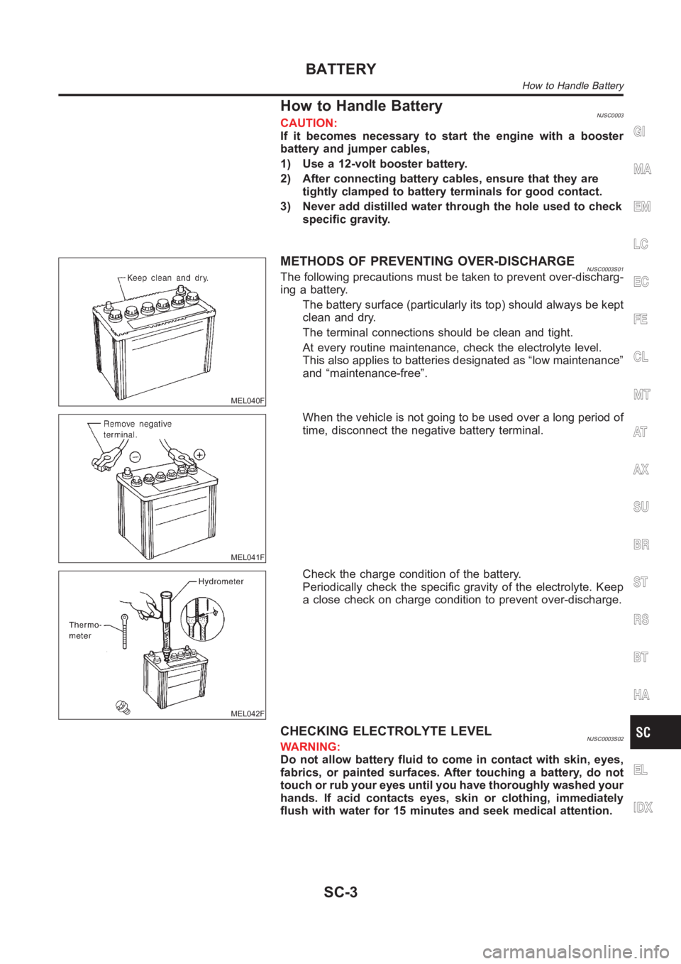
How to Handle BatteryNJSC0003CAUTION:
If it becomes necessary to start the engine with a booster
battery and jumper cables,
1) Use a 12-volt booster battery.
2) After connecting battery cables, ensure that they are
tightly clamped to battery terminals for good contact.
3) Never add distilled water through the hole used to check
specific gravity.
MEL040F
METHODS OF PREVENTING OVER-DISCHARGENJSC0003S01The following precautions must be taken to prevent over-discharg-
ing a battery.
The battery surface (particularly its top) should always be kept
clean and dry.
The terminal connections should be clean and tight.
At every routine maintenance, check the electrolyte level.
This also applies to batteries designated as “low maintenance”
and “maintenance-free”.
MEL041F
When the vehicle is not going to be used over a long period of
time, disconnect the negative battery terminal.
MEL042F
Check the charge condition of the battery.
Periodically check the specific gravity of the electrolyte. Keep
a close check on charge condition to prevent over-discharge.
CHECKING ELECTROLYTE LEVELNJSC0003S02WARNING:
Do not allow battery fluid to come in contact with skin, eyes,
fabrics, or painted surfaces. After touching a battery, do not
touch or rub your eyes until you have thoroughly washed your
hands. If acid contacts eyes, skin or clothing, immediately
flush with water for 15 minutes and seek medical attention.
GI
MA
EM
LC
EC
FE
CL
MT
AT
AX
SU
BR
ST
RS
BT
HA
EL
IDX
BATTERY
How to Handle Battery
SC-3
Page 3123 of 3189
Trouble DiagnosesNJSC0018If any abnormality is found, immediately disconnect battery negative terminal.
SEL761W
GI
MA
EM
LC
EC
FE
CL
MT
AT
AX
SU
BR
ST
RS
BT
HA
EL
IDX
STARTING SYSTEM
Trouble Diagnoses
SC-17
Page 3152 of 3189
Bleeding Hydraulic SystemNJST00141. Raise front end of vehicle until wheels are clear of the ground.
2. Add fluid into oil tank to specified level. Then quickly turn steer-
ing wheel fully to right and left and lightly touch steering stop-
pers.
Repeat steering wheel operation until fluid level no longer
decreases.
3. Start engine.
Repeat step 2. above.
Incomplete air bleeding will cause the following to occur. When
this happens, bleed air again.
a) Air bubbles in reservoir tank
b) Clicking noise in oil pump
c) Excessive buzzing in oil pump
Fluid noise may occur in the valve or oil pump. This is common
when the vehicle is stationary or while turning the steering wheel
slowly. This does not affect the performance or durability of the
system.
SST491B
SST090B
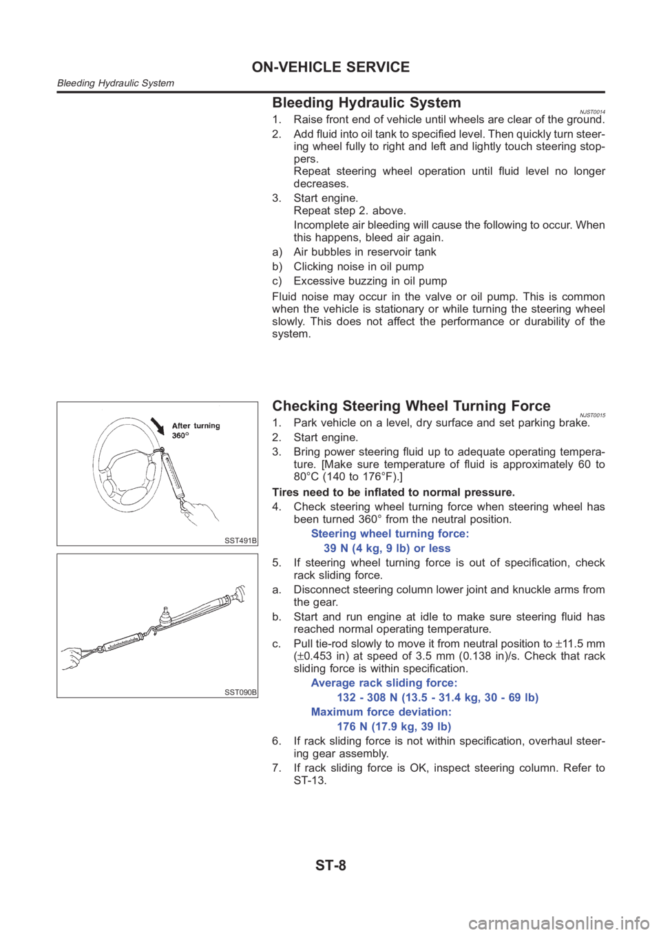
Checking Steering Wheel Turning ForceNJST00151. Park vehicle on a level, dry surface and set parking brake.
2. Start engine.
3. Bring power steering fluid up to adequate operating tempera-
ture. [Make sure temperature of fluid is approximately 60 to
80°C (140 to 176°F).]
Tires need to be inflated to normal pressure.
4. Check steering wheel turning force when steering wheel has
been turned 360° from the neutral position.
Steering wheel turning force:
39 N (4 kg, 9 lb) or less
5. If steering wheel turning force is out of specification, check
rack sliding force.
a. Disconnect steering column lower joint and knuckle arms from
the gear.
b. Start and run engine at idle to make sure steering fluid has
reached normal operating temperature.
c. Pull tie-rod slowly to move it from neutral position to±11 . 5 m m
(±0.453 in) at speed of 3.5 mm (0.138 in)/s. Check that rack
sliding force is within specification.
Average rack sliding force:
132 - 308 N (13.5 - 31.4 kg, 30 - 69 lb)
Maximum force deviation:
176 N (17.9 kg, 39 lb)
6. If rack sliding force is not within specification, overhaul steer-
ing gear assembly.
7. If rack sliding force is OK, inspect steering column. Refer to
ST-13.
ON-VEHICLE SERVICE
Bleeding Hydraulic System
ST-8
Page 3157 of 3189
Disassembly and Assembly=NJST0019
YST027
1. Combination switch with spiral
cable
2. Lock nut
3. Jacket tube assembly4. Column shaft assembly
5. Seal cover
6. Lower seal cover7. Hole cover
8. Steering column lower cover
9. Tie strap
SST490C
When disassembling and assembling, unlock steering lock
with key.
Remove combination switch.
Install lock nut on steering column shaft and tighten the nut.
SST741A
Steering lock
a) Break self-shear type screws with a drill or other appropriate
tool.
GI
MA
EM
LC
EC
FE
CL
MT
AT
AX
SU
BR
RS
BT
HA
SC
EL
IDX
STEERING WHEEL AND STEERING COLUMN
Disassembly and Assembly
ST-13