2003 NISSAN ALMERA N16 iat
[x] Cancel search: iatPage 1990 of 3189
ATC-10
PRECAUTIONS
●A compressor shaft seal should not be repaired because of dye seepage. The compressor shaft seal
should only be repaired after confirming the leak with an electronic refrigerant leak detector (J-41995).
●Always remove any remaining dye from the leak area after repairs are complete to avoid a misdiagnosis
during a future service.
●Do not allow dye to come into contact with painted body panels or interior components. If dye is spilled,
clean immediately with the approved dye cleaner. Fluorescent dye left on a surface for an extended period
of time cannot be removed.
●Do not spray the fluorescent dye cleaning agent on hot surfaces (engine exhaust manifold, etc.).
●Do not use more than one refrigerant dye bottle (1/4 ounce / 7.4 cc) per A/C system.
●Leak detection dyes for HFC-134a (R-134a) and CFC-12 (R-12) A/C systems are different. Do not use
HFC-134a (R-134a) leak detection dye in CFC-12 (R-12) A/C system or CFC-12 (R-12) leak detector dye
in HFC-134a (R-134a) A/C systems or A/C system damage may result.
●The fluorescent properties of the dye will remain for over three (3) years unless a compressor malfunction
occurs.
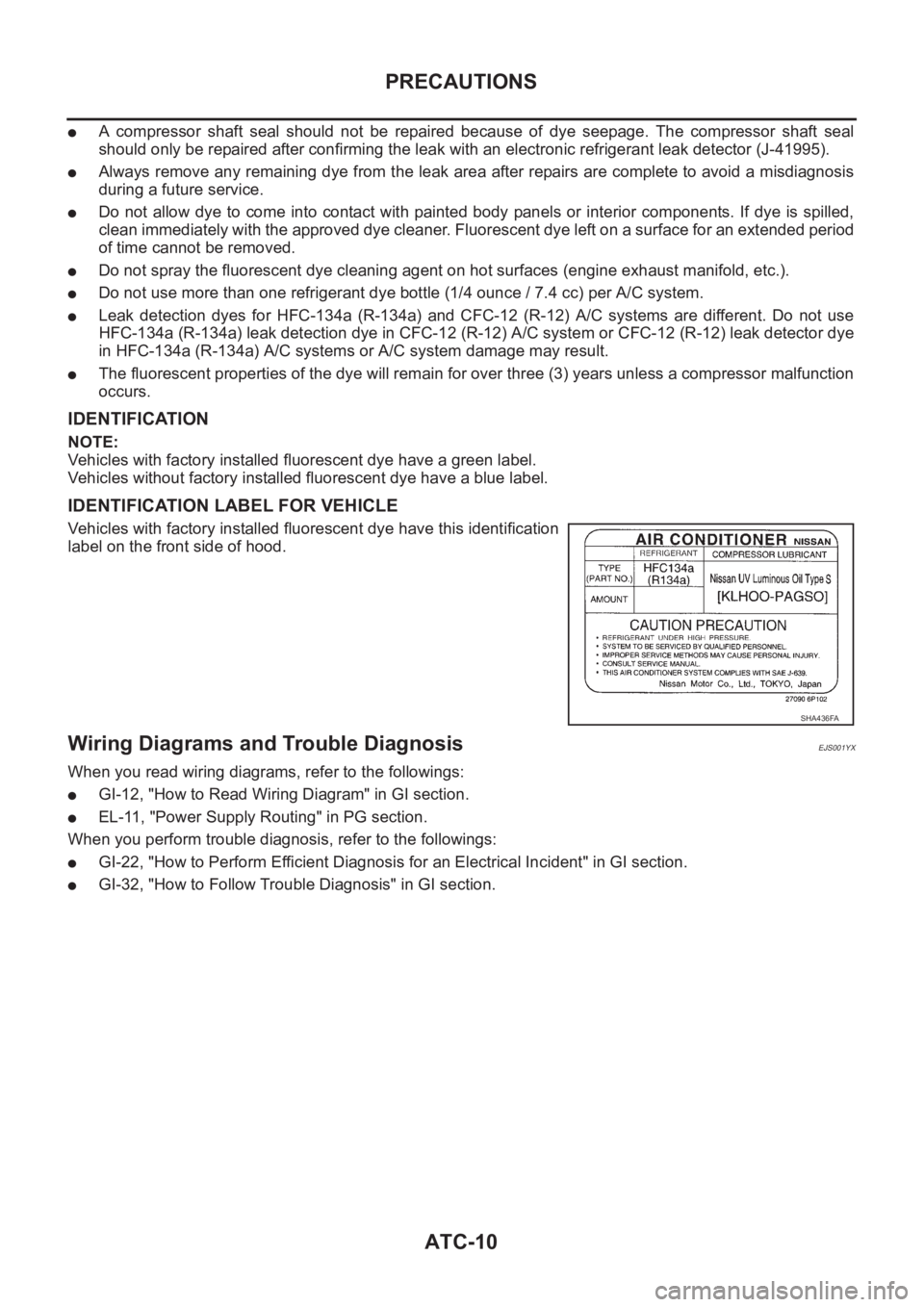
IDENTIFICATION
NOTE:
Vehicles with factory installed fluorescent dye have a green label.
Vehicles without factory installed fluorescent dye have a blue label.
IDENTIFICATION LABEL FOR VEHICLE
Vehicles with factory installed fluorescent dye have this identification
label on the front side of hood.
Wiring Diagrams and Trouble DiagnosisEJS001YX
When you read wiring diagrams, refer to the followings:
●GI-12, "How to Read Wiring Diagram" in GI section.
●EL-11, "Power Supply Routing" in PG section.
When you perform trouble diagnosis, refer to the followings:
●GI-22, "How to Perform Efficient Diagnosis for an Electrical Incident" in GI section.
●GI-32, "How to Follow Trouble Diagnosis" in GI section.
SHA436FA
Page 2003 of 3189
AIR CONDITIONER CONTROL
ATC-23
C
D
E
F
G
H
I
K
L
MA
B
AT C
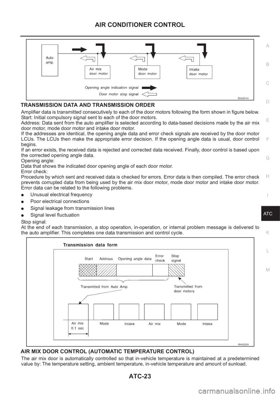
TRANSMISSION DATA AND TRANSMISSION ORDER
Amplifier data is transmitted consecutively to each of the door motors following the form shown in figure below.
Start: Initial compulsory signal sent to each of the door motors.
Address: Data sent from the auto amplifier is selected according to data-based decisions made by the air mix
door motor, mode door motor and intake door motor.
If the addresses are identical, the opening angle data and error check signals are received by the door motor
LCUs. The LCUs then make the appropriate error decision. If the opening angle data is usual, door control
begins.
If an error exists, the received data is rejected and corrected data received. Finally, door control is based upon
the corrected opening angle data.
Opening angle:
Data that shows the indicated door opening angle of each door motor.
Error check:
Procedure by which sent and received data is checked for errors. Error data is then compiled. The error check
prevents corrupted data from being used by the air mix door motor, mode door motor and intake door motor.
Error data can be related to the following problems.
●Unusual electrical frequency
●Poor electrical connections
●Signal leakage from transmission lines
●Signal level fluctuation
Stop signal:
At the end of each transmission, a stop operation, in-operation, or internal problem message is delivered to
the auto amplifier. This completes one data transmission and control cycle.
AIR MIX DOOR CONTROL (AUTOMATIC TEMPERATURE CONTROL)
The air mix door is automatically controlled so that in-vehicle temperature is maintained at a predetermined
value by: The temperature setting, ambient temperature, in-vehicle temperature and amount of sunload.
RHA351H
RHA352H
Page 2080 of 3189
ATC-100
TROUBLE DIAGNOSIS
Ambient Sensor Circuit
EJS001ZV
COMPONENT DESCRIPTION
Ambient Sensor
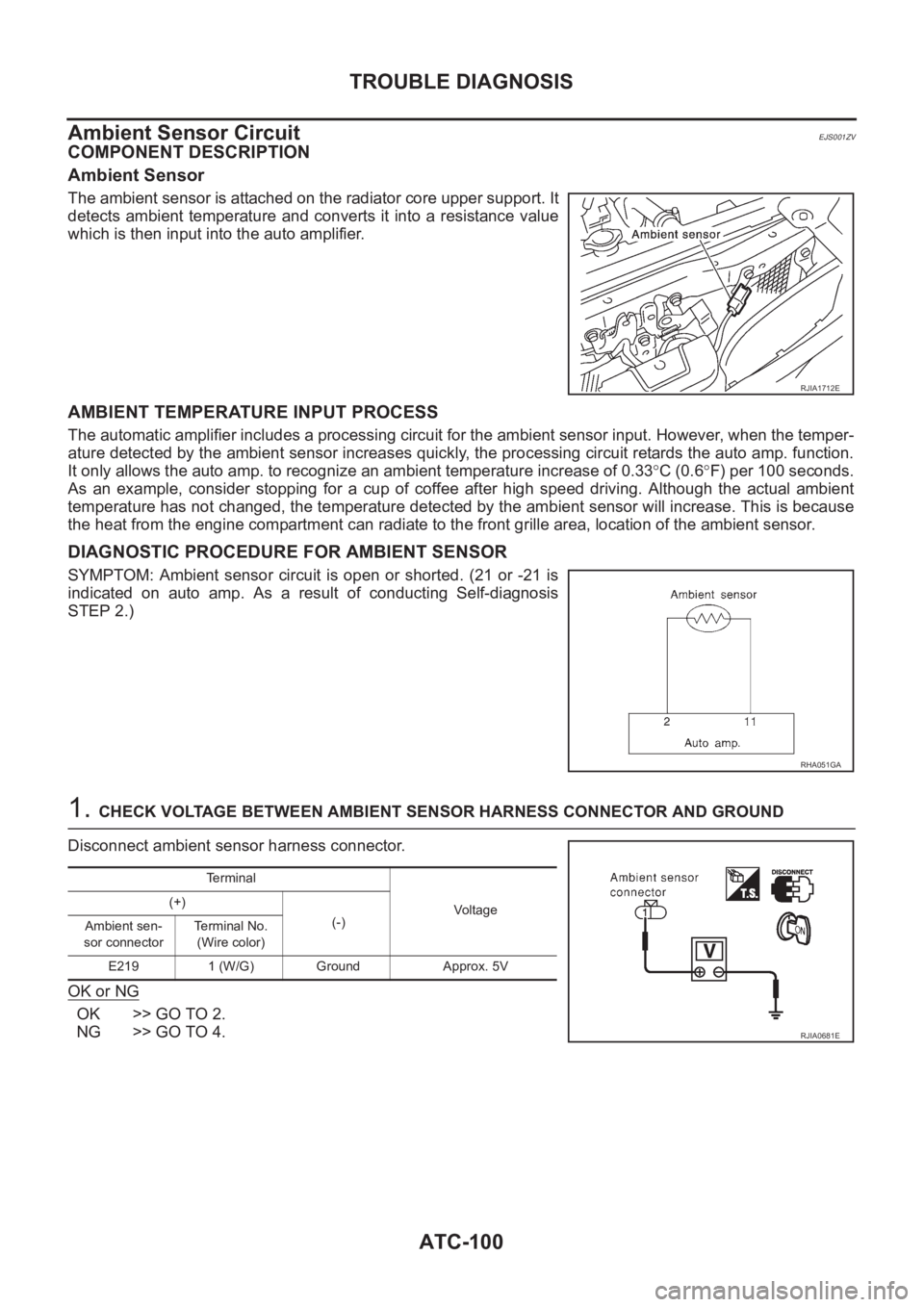
The ambient sensor is attached on the radiator core upper support. It
detects ambient temperature and converts it into a resistance value
which is then input into the auto amplifier.
AMBIENT TEMPERATURE INPUT PROCESS
The automatic amplifier includes a processing circuit for the ambient sensor input. However, when the temper-
ature detected by the ambient sensor increases quickly, the processing circuit retards the auto amp. function.
It only allows the auto amp. to recognize an ambient temperature increase of 0.33°C (0.6°F) per 100 seconds.
As an example, consider stopping for a cup of coffee after high speed driving. Although the actual ambient
temperature has not changed, the temperature detected by the ambient sensor will increase. This is because
the heat from the engine compartment can radiate to the front grille area, location of the ambient sensor.
DIAGNOSTIC PROCEDURE FOR AMBIENT SENSOR
SYMPTOM: Ambient sensor circuit is open or shorted. (21 or -21 is
indicated on auto amp. As a result of conducting Self-diagnosis
STEP 2.)
1. CHECK VOLTAGE BETWEEN AMBIENT SENSOR HARNESS CONNECTOR AND GROUND
Disconnect ambient sensor harness connector.
OK or NG
OK >> GO TO 2.
NG >> GO TO 4.
RJIA1712E
RHA051GA
Terminal
Voltage (+)
(-)
Ambient sen-
sor connectorTerminal No.
(Wire color)
E219 1 (W/G) Ground Approx. 5V
RJIA0681E
Page 2082 of 3189
ATC-102
TROUBLE DIAGNOSIS
COMPONENT INSPECTION
Ambient Sensor
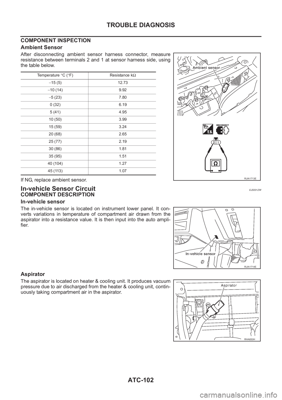
After disconnecting ambient sensor harness connector, measure
resistance between terminals 2 and 1 at sensor harness side, using
the table below.
If NG, replace ambient sensor.
In-vehicle Sensor CircuitEJS001ZW
COMPONENT DESCRIPTION
In-vehicle sensor
The in-vehicle sensor is located on instrument lower panel. It con-
verts variations in temperature of compartment air drawn from the
aspirator into a resistance value. It is then input into the auto ampli-
fier.
Aspirator
The aspirator is located on heater & cooling unit. It produces vacuum
pressure due to air discharged from the heater & cooling unit, contin-
uously taking compartment air in the aspirator.
Temperature °C (°F) Resistance kΩ
−15 (5) 12.73
−10 (14) 9.92
−5 (23) 7.80
0 (32) 6.19
5 (41) 4.95
10 (50) 3.99
15 (59) 3.24
20 (68) 2.65
25 (77) 2.19
30 (86) 1.81
35 (95) 1.51
40 (104) 1.27
45 (113) 1.07
RJIA1713E
RJIA1714E
RHA650H
Page 2085 of 3189
TROUBLE DIAGNOSIS
ATC-105
C
D
E
F
G
H
I
K
L
MA
B
AT C
Sunload Sensor CircuitEJS001ZX
COMPONENT DESCRIPTION
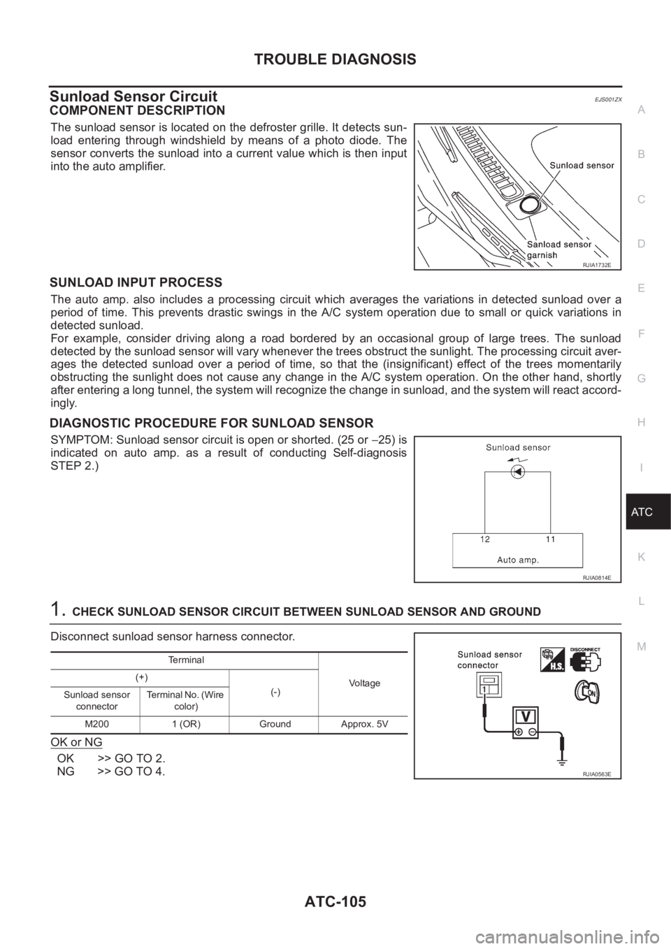
The sunload sensor is located on the defroster grille. It detects sun-
load entering through windshield by means of a photo diode. The
sensor converts the sunload into a current value which is then input
into the auto amplifier.
SUNLOAD INPUT PROCESS
The auto amp. also includes a processing circuit which averages the variations in detected sunload over a
period of time. This prevents drastic swings in the A/C system operation due to small or quick variations in
detected sunload.
For example, consider driving along a road bordered by an occasional group of large trees. The sunload
detected by the sunload sensor will vary whenever the trees obstruct the sunlight. The processing circuit aver-
ages the detected sunload over a period of time, so that the (insignificant) effect of the trees momentarily
obstructing the sunlight does not cause any change in the A/C system operation. On the other hand, shortly
after entering a long tunnel, the system will recognize the change in sunload, and the system will react accord-
ingly.
DIAGNOSTIC PROCEDURE FOR SUNLOAD SENSOR
SYMPTOM: Sunload sensor circuit is open or shorted. (25 or −25) is
indicated on auto amp. as a result of conducting Self-diagnosis
STEP 2.)
1.CHECK SUNLOAD SENSOR CIRCUIT BETWEEN SUNLOAD SENSOR AND GROUND
Disconnect sunload sensor harness connector.
OK or NG
OK >> GO TO 2.
NG >> GO TO 4.
RJIA1732E
RJIA0814E
Te r m i n a l
Voltage (+)
(-)
Sunload sensor
connectorTerminal No. (Wire
color)
M200 1 (OR) Ground Approx. 5V
RJIA0563E
Page 2103 of 3189
HEATER & COOLING UNIT ASSEMBLY
ATC-123
C
D
E
F
G
H
I
K
L
MA
B
AT C
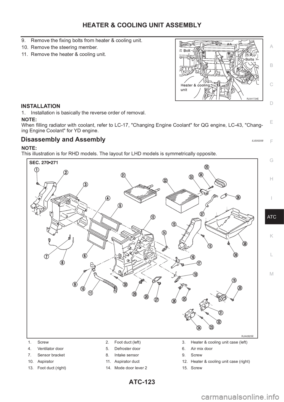
9. Remove the fixing bolts from heater & cooling unit.
10. Remove the steering member.
11. Remove the heater & cooling unit.
INSTALLATION
1. Installation is basically the reverse order of removal.
NOTE:
When filling radiator with coolant, refer to LC-17, "Changing Engine Coolant" for QG engine, LC-43, "Chang-
ing Engine Coolant" for YD engine.
Disassembly and AssemblyEJS0020B
NOTE:
This illustration is for RHD models. The layout for LHD models is symmetrically opposite.
RJIA1724E
1. Screw 2. Foot duct (left) 3. Heater & cooling unit case (left)
4. Ventilator door 5. Defroster door 6. Air mix door
7. Sensor bracket 8. Intake sensor 9. Screw
10. Aspirator 11. Aspirator duct 12. Heater & cooling unit case (right)
13. Foot duct (right) 14. Mode door lever 2 15. Screw
RJIA0825E
Page 2123 of 3189
REFRIGERANT LINES
ATC-143
C
D
E
F
G
H
I
K
L
MA
B
AT C
Dual-pressure SwitchEJS0020Q
REMOVAL AND INSTALLATION
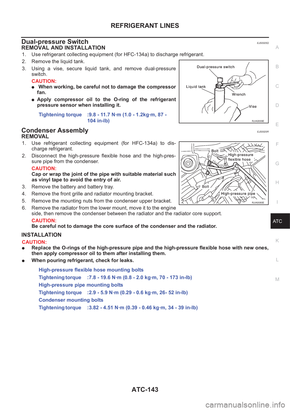
1. Use refrigerant collecting equipment (for HFC-134a) to discharge refrigerant.
2. Remove the liquid tank.
3. Using a vise, secure liquid tank, and remove dual-pressure
switch.
CAUTION:
● When working, be careful not to damage the compressor
fan.
●Apply compressor oil to the O-ring of the refrigerant
pressure sensor when installing it.
Condenser AssemblyEJS0020R
REMOVAL
1. Use refrigerant collecting equipment (for HFC-134a) to dis-
charge refrigerant.
2. Disconnect the high-pressure flexible hose and the high-pres-
sure pipe from the condenser.
CAUTION:
Cap or wrap the joint of the pipe with suitable material such
as vinyl tape to avoid the entry of air.
3. Remove the battery and battery tray.
4. Remove the front grille and radiator mounting bracket.
5. Remove the mounting nuts from the condenser upper bracket.
6. Remove the radiator from the lower mount, move it to the engine
side, then remove the condenser between the radiator and the radiator core support.
CAUTION:
Be careful not to damage the core surface of the condenser and the radiator.
INSTALLATION
CAUTION:
●Replace the O-rings of the high-pressure pipe and the high-pressure flexible hose with new ones,
then apply compressor oil to them after installing them.
●When pouring refrigerant, check for leaks.Tightening torque :9.8 - 11.7 N·m (1.0 - 1.2kg·m, 87 -
104 in-lb)
RJIA0699E
RJIA0080E
High-pressure flexible hose mounting bolts
Tightening torque :7.8 - 19.6 N·m (0.8 - 2.0 kg·m, 70 - 173 in-lb)
High-pressure pipe mounting bolts
Tightening torque :2.9 - 5.9 N·m (0.29 - 0.6 kg·m, 26- 52 in-lb)
Condenser mounting bolts
Tightening torque :3.82 - 4.51 N·m (0.39 - 0.46 kg·m, 34 - 39 in-lb)
Page 2128 of 3189
ATC-148
REFRIGERANT LINES
9. Run engine at 1,500 rpm for at least 2 minutes.
10. Turn engine OFF and perform leak check again following steps 4 through 6 above.
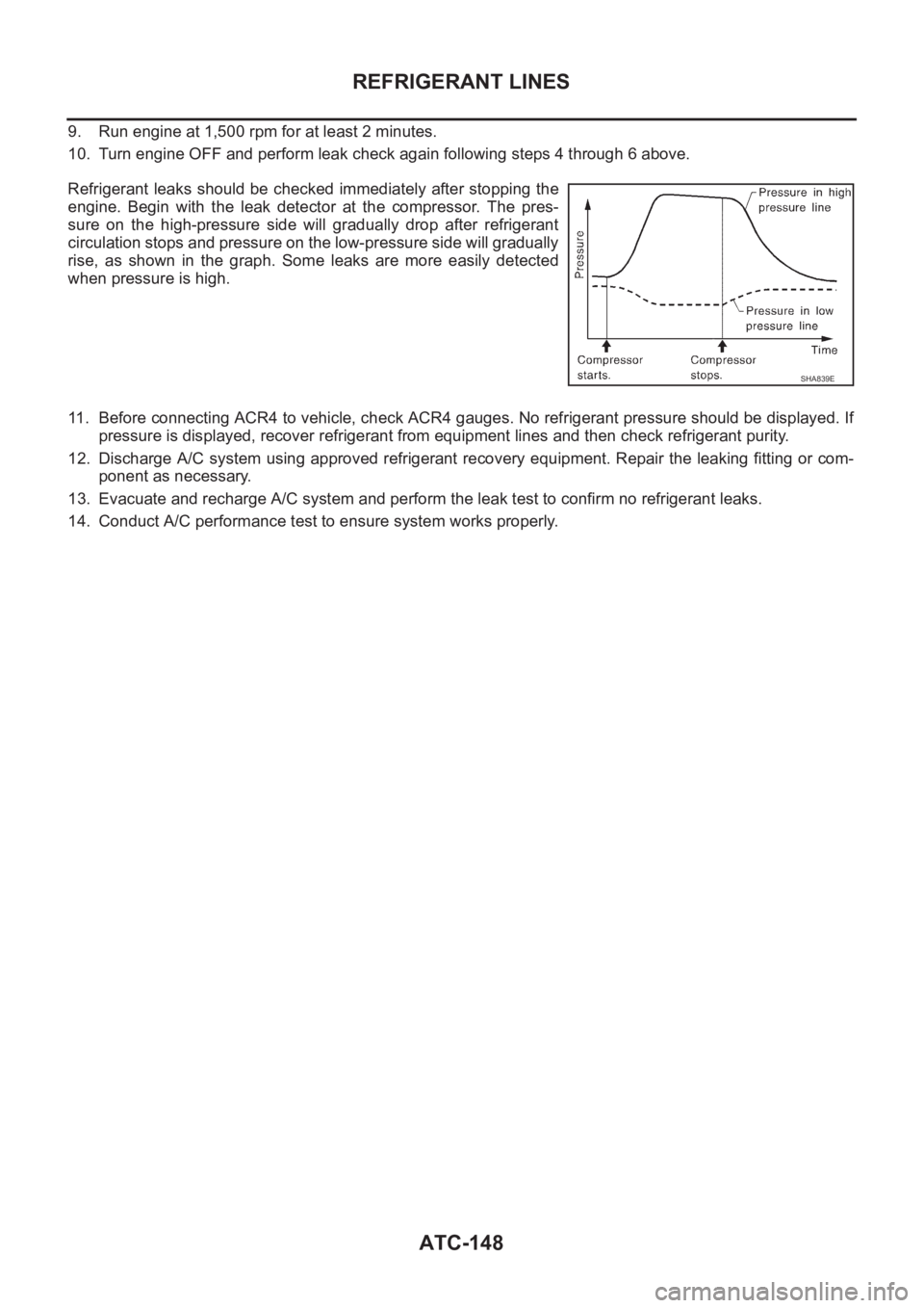
Refrigerant leaks should be checked immediately after stopping the
engine. Begin with the leak detector at the compressor. The pres-
sure on the high-pressure side will gradually drop after refrigerant
circulation stops and pressure on the low-pressure side will gradually
rise, as shown in the graph. Some leaks are more easily detected
when pressure is high.
11. Before connecting ACR4 to vehicle, check ACR4 gauges. No refrigerant pressure should be displayed. If
pressure is displayed, recover refrigerant from equipment lines and then check refrigerant purity.
12. Discharge A/C system using approved refrigerant recovery equipment. Repair the leaking fitting or com-
ponent as necessary.
13. Evacuate and recharge A/C system and perform the leak test to confirm no refrigerant leaks.
14. Conduct A/C performance test to ensure system works properly.
SHA839E