2003 NISSAN ALMERA N16 iat
[x] Cancel search: iatPage 974 of 3189
![NISSAN ALMERA N16 2003 Electronic Repair Manual EC-644
[QG (WITHOUT EURO-OBD)]
IAT SENSOR
Wiring Diagram
EBS00KKN
YEC317A NISSAN ALMERA N16 2003 Electronic Repair Manual EC-644
[QG (WITHOUT EURO-OBD)]
IAT SENSOR
Wiring Diagram
EBS00KKN
YEC317A](/manual-img/5/57350/w960_57350-973.png)
EC-644
[QG (WITHOUT EURO-OBD)]
IAT SENSOR
Wiring Diagram
EBS00KKN
YEC317A
Page 975 of 3189
![NISSAN ALMERA N16 2003 Electronic Repair Manual IAT SENSOR
EC-645
[QG (WITHOUT EURO-OBD)]
C
D
E
F
G
H
I
J
K
L
MA
EC
Diagnostic ProcedureEBS00KKO
1.CHECK OVERALL FUNCTION
1. Turn ignition switch “ON”.
2. Check voltage between ECM terminal 34 and NISSAN ALMERA N16 2003 Electronic Repair Manual IAT SENSOR
EC-645
[QG (WITHOUT EURO-OBD)]
C
D
E
F
G
H
I
J
K
L
MA
EC
Diagnostic ProcedureEBS00KKO
1.CHECK OVERALL FUNCTION
1. Turn ignition switch “ON”.
2. Check voltage between ECM terminal 34 and](/manual-img/5/57350/w960_57350-974.png)
IAT SENSOR
EC-645
[QG (WITHOUT EURO-OBD)]
C
D
E
F
G
H
I
J
K
L
MA
EC
Diagnostic ProcedureEBS00KKO
1.CHECK OVERALL FUNCTION
1. Turn ignition switch “ON”.
2. Check voltage between ECM terminal 34 and ground with CON-
SULT-II or tester.
OK or NG
OK >>INSPECTION END.
NG >> GO TO 2.
2.CHECK INTAKE AIR TEMPERATURE SENSOR POWER SUPPLY CIRCUIT
1. Turn ignition switch “OFF”.
2. Disconnect mass air flow sensor (intake air temperature sensor
is built-into) harness connector.
3. Turn ignition switch “ON”.
4. Check voltage between MAF sensor terminal 5 and ground.
OK or NG
OK >> GO TO 3.
NG >> Repair open circuit or short to ground or short to power
in harness or connectors.
3.CHECK INTAKE AIR TEMPERATURE SENSOR GROUND CIRCUIT FOR OPEN AND SHORT
1. Turn ignition switch “OFF”.
2. Disconnect ECM harness connector.
3. Check harness continuity between ECM terminal 67 and mass air flow sensor terminal 3.
Refer to Wiring Diagram.
4. Also check harness for short to ground and short to power.
OK or NG
OK >> GO TO 4.
NG >> Repair open circuit or short to ground or short to power in harness or connectors. Voltage: Approximately 0 - 4.8V
MBIB0041E
MBIB0096E
Voltage: Approximately 5V
PBIB0066E
Continuity should exist.
Page 976 of 3189
![NISSAN ALMERA N16 2003 Electronic Repair Manual EC-646
[QG (WITHOUT EURO-OBD)]
IAT SENSOR
4. CHECK INTAKE AIR TEMPERATURE SENSOR
Refer to EC-646, "
Component Inspection" .
OK or NG
OK >> GO TO 5.
NG >> Replace mass air flow sensor (with int NISSAN ALMERA N16 2003 Electronic Repair Manual EC-646
[QG (WITHOUT EURO-OBD)]
IAT SENSOR
4. CHECK INTAKE AIR TEMPERATURE SENSOR
Refer to EC-646, "
Component Inspection" .
OK or NG
OK >> GO TO 5.
NG >> Replace mass air flow sensor (with int](/manual-img/5/57350/w960_57350-975.png)
EC-646
[QG (WITHOUT EURO-OBD)]
IAT SENSOR
4. CHECK INTAKE AIR TEMPERATURE SENSOR
Refer to EC-646, "
Component Inspection" .
OK or NG
OK >> GO TO 5.
NG >> Replace mass air flow sensor (with intake air temperature sensor).
5. CHECK INTERMITTENT INCIDENT
Refer to EC-485, "
TROUBLE DIAGNOSIS FOR INTERMITTENT INCIDENT" .
>>INSPECTION END
Component InspectionEBS00KKP
INTAKE AIR TEMPERATURE SENSOR
1. Check resistance between intake air temperature sensor termi-
nals 3 and 5 under the following conditions.
2. If NG, replace mass air flow sensor (with intake air temperature
sensor).
Removal and InstallationEBS00KKQ
MASS AIR FLOW SENSOR
Refer to EM-14, "AIR CLEANER AND AIR DUCT" .
Intake air temperature °C (°F) Resistance kΩ
25 (77) 1.9 - 2.1
SEC266C
SEF012P
Page 1050 of 3189
![NISSAN ALMERA N16 2003 Electronic Repair Manual EC-720
[QG (WITHOUT EURO-OBD)]
POSITIVE CRANKCASE VENTILATION
POSITIVE CRANKCASE VENTILATION
PFP:11810
DescriptionEBS00KMJ
SYSTEM DESCRIPTION
This system returns blow-by gas to the intake manifold.
Th NISSAN ALMERA N16 2003 Electronic Repair Manual EC-720
[QG (WITHOUT EURO-OBD)]
POSITIVE CRANKCASE VENTILATION
POSITIVE CRANKCASE VENTILATION
PFP:11810
DescriptionEBS00KMJ
SYSTEM DESCRIPTION
This system returns blow-by gas to the intake manifold.
Th](/manual-img/5/57350/w960_57350-1049.png)
EC-720
[QG (WITHOUT EURO-OBD)]
POSITIVE CRANKCASE VENTILATION
POSITIVE CRANKCASE VENTILATION
PFP:11810
DescriptionEBS00KMJ
SYSTEM DESCRIPTION
This system returns blow-by gas to the intake manifold.
The positive crankcase ventilation (PCV) valve is provided to conduct crankcase blow-by gas to the intake
manifold. During partial throttle operation of the engine, the intake manifold sucks the blow-by gas through the
PCV valve. Normally, the capacity of the valve is sufficient to handle any blow-by and a small amount of venti-
lating air. The ventilating air is then drawn from the air inlet tubes into the crankcase. In this process the air
passes through the hose connecting air inlet tubes to rocker cover. Under full-throttle condition, the manifold
vacuum is insufficient to draw the blow-by flow through the valve. The flow goes through the hose connection
in the reverse direction.
On vehicles with an excessively high blow-by, the valve does not
meet the requirement. This is because some of the flow will go
through the hose connection to the air inlet tubes under all condi-
tions.
Component InspectionEBS00KMK
PCV (POSITIVE CRANKCASE VENTILATION) VALVE
With engine running at idle, remove PCV valve from rocker cover. A
properly working valve makes a hissing noise as air passes through
it. A strong vacuum should be felt immediately when a finger is
placed over valve inlet.
PBIB0492E
SEF559A
SEC137A
Page 1071 of 3189

Fuel Injection Control System
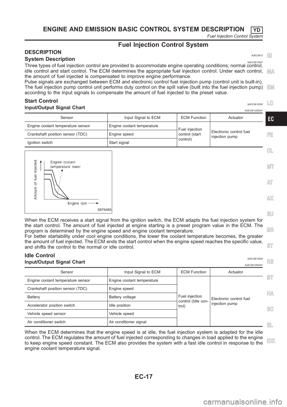
DESCRIPTIONNJEC0612System DescriptionNJEC0612S01Three types of fuel injection control are provided to accommodate engine operating conditions; normal control,
idle control and start control. The ECM determines the appropriate fuel injection control. Under each control,
the amount of fuel injected is compensated to improve engine performance.
Pulse signals are exchanged between ECM and electronic control fuel injection pump (control unit is built-in).
The fuel injection pump control unit performs duty control on the spill valve (built into the fuel injection pump)
according to the input signals to compensate the amount of fuel injected tothe preset value.
Start ControlNJEC0612S02Input/Output Signal ChartNJEC0612S0201
Sensor Input Signal to ECM ECM Function Actuator
Engine coolant temperature sensor Engine coolant temperature
Fuel injection
control (start
control)Electronic control fuel
injection pump Crankshaft position sensor (TDC) Engine speed
Ignition switch Start signal
SEF648S
When the ECM receives a start signal from the ignition switch, the ECM adapts the fuel injection system for
the start control. The amount of fuel injected at engine starting is a preset program value in the ECM. The
program is determined by the engine speed and engine coolant temperature.
For better startability under cool engine conditions, the lower the coolant temperature becomes, the greater
the amount of fuel injected. The ECM ends the start control when the engine speed reaches the specific value,
and shifts the control to the normal or idle control.
Idle ControlNJEC0612S03Input/Output Signal ChartNJEC0612S0301
Sensor Input Signal to ECM ECM Function Actuator
Engine coolant temperature sensor Engine coolant temperature
Fuel injection
control (Idle con-
trol)Electronic control fuel
injection pump Crankshaft position sensor (TDC) Engine speed
Battery Battery voltage
Accelerator position switch Idle position
Vehicle speed sensor Vehicle speed
Air conditioner switch Air conditioner signal
When the ECM determines that the engine speed is at idle, the fuel injectionsystem is adapted for the idle
control. The ECM regulates the amount of fuel injected corresponding to changes in load applied to the engine
to keep engine speed constant. The ECM also provides the system with a fast idle control in response to the
engine coolant temperature signal.
GI
MA
EM
LC
FE
CL
MT
AT
AX
SU
BR
ST
RS
BT
HA
SC
EL
IDX
ENGINE AND EMISSION BASIC CONTROL SYSTEM DESCRIPTIONYD
Fuel Injection Control System
EC-17
Page 1101 of 3189

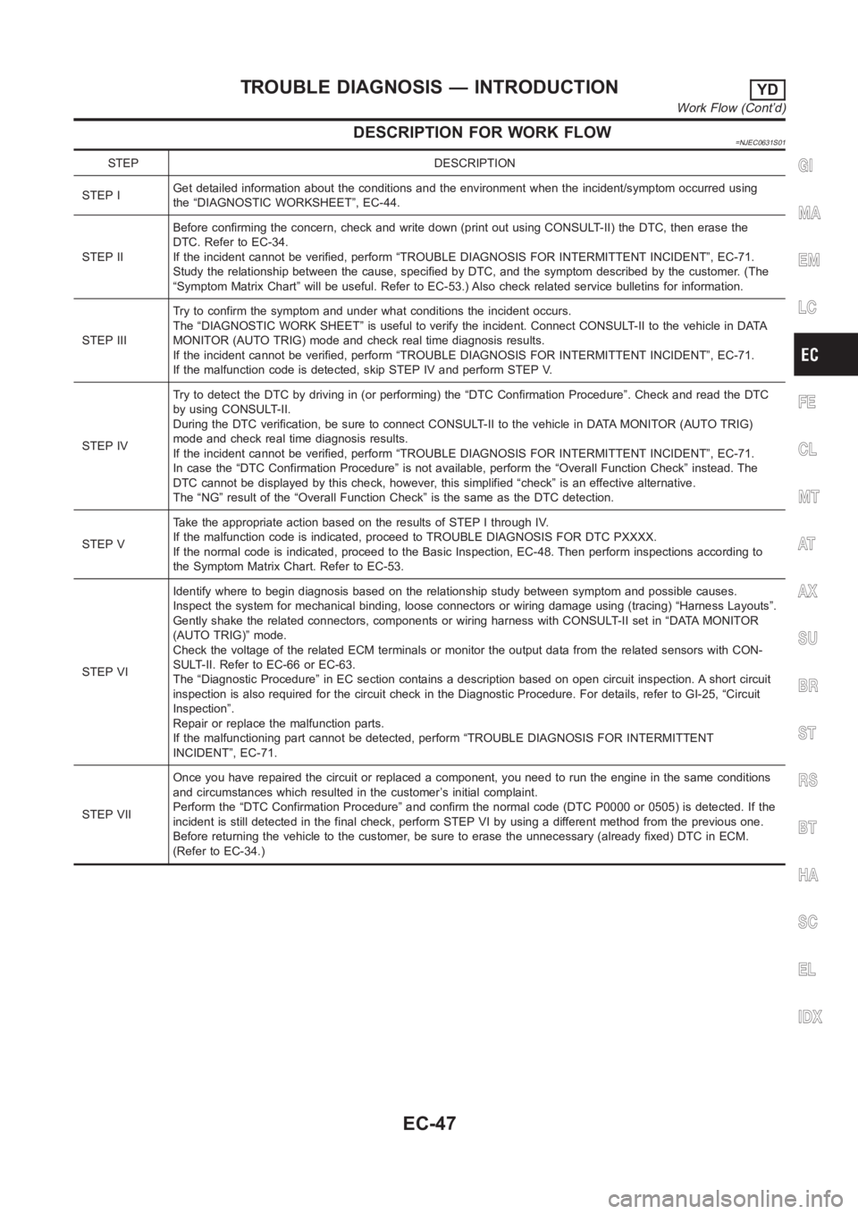
DESCRIPTION FOR WORK FLOW=NJEC0631S01
STEP DESCRIPTION
STEP IGet detailed information about the conditions and the environment when the incident/symptom occurred using
the “DIAGNOSTIC WORKSHEET”, EC-44.
STEP IIBefore confirming the concern, check and write down (print out using CONSULT-II) the DTC, then erase the
DTC. Refer to EC-34.
If the incident cannot be verified, perform “TROUBLE DIAGNOSIS FOR INTERMITTENT INCIDENT”, EC-71.
Study the relationship between the cause, specified by DTC, and the symptom described by the customer. (The
“Symptom Matrix Chart” will be useful. Refer to EC-53.) Also check relatedservice bulletins for information.
STEP IIITry to confirm the symptom and under what conditions the incident occurs.
The “DIAGNOSTIC WORK SHEET” is useful to verify the incident. Connect CONSULT-II to the vehicle in DATA
MONITOR (AUTO TRIG) mode and check real time diagnosis results.
If the incident cannot be verified, perform “TROUBLE DIAGNOSIS FOR INTERMITTENT INCIDENT”, EC-71.
If the malfunction code is detected, skip STEP IV and perform STEP V.
STEP IVTry to detect the DTC by driving in (or performing) the “DTC Confirmation Procedure”. Check and read the DTC
by using CONSULT-II.
During the DTC verification, be sure to connect CONSULT-II to the vehicle in DATA MONITOR (AUTO TRIG)
mode and check real time diagnosis results.
If the incident cannot be verified, perform “TROUBLE DIAGNOSIS FOR INTERMITTENT INCIDENT”, EC-71.
In case the “DTC Confirmation Procedure” is not available, perform the “Overall Function Check” instead. The
DTC cannot be displayed by this check, however, this simplified “check” isan effective alternative.
The “NG” result of the “Overall Function Check” is the same as the DTC detection.
STEP VTake the appropriate action based on the results of STEP I through IV.
If the malfunction code is indicated, proceed to TROUBLE DIAGNOSIS FOR DTCPXXXX.
If the normal code is indicated, proceed to the Basic Inspection, EC-48. Then perform inspections according to
the Symptom Matrix Chart. Refer to EC-53.
STEP VIIdentify where to begin diagnosis based on the relationship study betweensymptom and possible causes.
Inspect the system for mechanical binding, loose connectors or wiring damage using (tracing) “Harness Layouts”.
Gently shake the related connectors, components or wiring harness with CONSULT-II set in “DATA MONITOR
(AUTO TRIG)” mode.
Check the voltage of the related ECM terminals or monitor the output data from the related sensors with CON-
SULT-II. Refer to EC-66 or EC-63.
The “Diagnostic Procedure” in EC section contains a description based on open circuit inspection. A short circuit
inspection is also required for the circuit check in the Diagnostic Procedure. For details, refer to GI-25, “Circuit
Inspection”.
Repair or replace the malfunction parts.
If the malfunctioning part cannot be detected, perform “TROUBLE DIAGNOSIS FOR INTERMITTENT
INCIDENT”, EC-71.
STEP VIIOnce you have repaired the circuit or replaced a component, you need to run the engine in the same conditions
and circumstances which resulted in the customer’s initial complaint.
Perform the “DTC Confirmation Procedure” and confirm the normal code (DTCP0000 or 0505) is detected. If the
incident is still detected in the final check, perform STEP VI by using a different method from the previous one.
Before returning the vehicle to the customer, be sure to erase the unnecessary (already fixed) DTC in ECM.
(Refer to EC-34.)GI
MA
EM
LC
FE
CL
MT
AT
AX
SU
BR
ST
RS
BT
HA
SC
EL
IDX
TROUBLE DIAGNOSIS — INTRODUCTIONYD
Work Flow (Cont’d)
EC-47
Page 1172 of 3189

SEF437Y
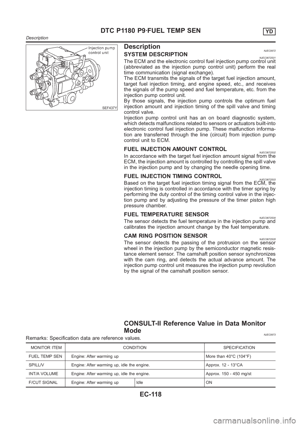
DescriptionNJEC0672SYSTEM DESCRIPTIONNJEC0672S01The ECM and the electronic control fuel injection pump control unit
(abbreviated as the injection pump control unit) perform the real
time communication (signal exchange).
The ECM transmits the signals of the target fuel injection amount,
target fuel injection timing, and engine speed, etc., and receives
the signals of the pump speed and fuel temperature, etc. from the
injection pump control unit.
By those signals, the injection pump controls the optimum fuel
injection amount and injection timing of the spill valve and timing
control valve.
Injection pump control unit has an on board diagnostic system,
which detects malfunctions related to sensors or actuators built-into
electronic control fuel injection pump. These malfunction informa-
tion are transferred through the line (circuit) from injection pump
control unit to ECM.
FUEL INJECTION AMOUNT CONTROLNJEC0672S02In accordance with the target fuel injection amount signal from the
ECM, the injection amount is controlled by controlling the spill valve
in the injection pump and by changing the needle opening time.
FUEL INJECTION TIMING CONTROLNJEC0672S03Based on the target fuel injection timing signal from the ECM, the
injection timing is controlled in accordance with the timer spring by
performing the duty control of the timing control valve in the injec-
tion pump and by adjusting the pressure of the timer piston high
pressure chamber.
FUEL TEMPERATURE SENSORNJEC0672S04The sensor detects the fuel temperature in the injection pump and
calibrates the injection amount change by the fuel temperature.
CAM RING POSITION SENSORNJEC0672S05The sensor detects the passing of the protrusion on the sensor
wheel in the injection pump by the semiconductor magnetic resis-
tance element sensor. The camshaft position sensor synchronizes
with the cam ring, and detects the actual advance amount. The
injection pump control unit measures the injection pump revolution
by the signal of the camshaft position sensor.
CONSULT-II Reference Value in Data Monitor
Mode
NJEC0673Remarks: Specification data are reference values.
MONITOR ITEM CONDITION SPECIFICATION
FUEL TEMP SEN Engine: After warming up More than 40°C (104°F)
SPILL/V Engine: After warming up, idle the engine. Approx. 12 - 13°CA
INT/A VOLUME Engine: After warming up, idle the engine. Approx. 150 - 450 mg/st
F/CUT SIGNAL Engine: After warming up Idle ON
DTC P1180 P9·FUEL TEMP SENYD
Description
EC-118
Page 1178 of 3189

SEF437Y
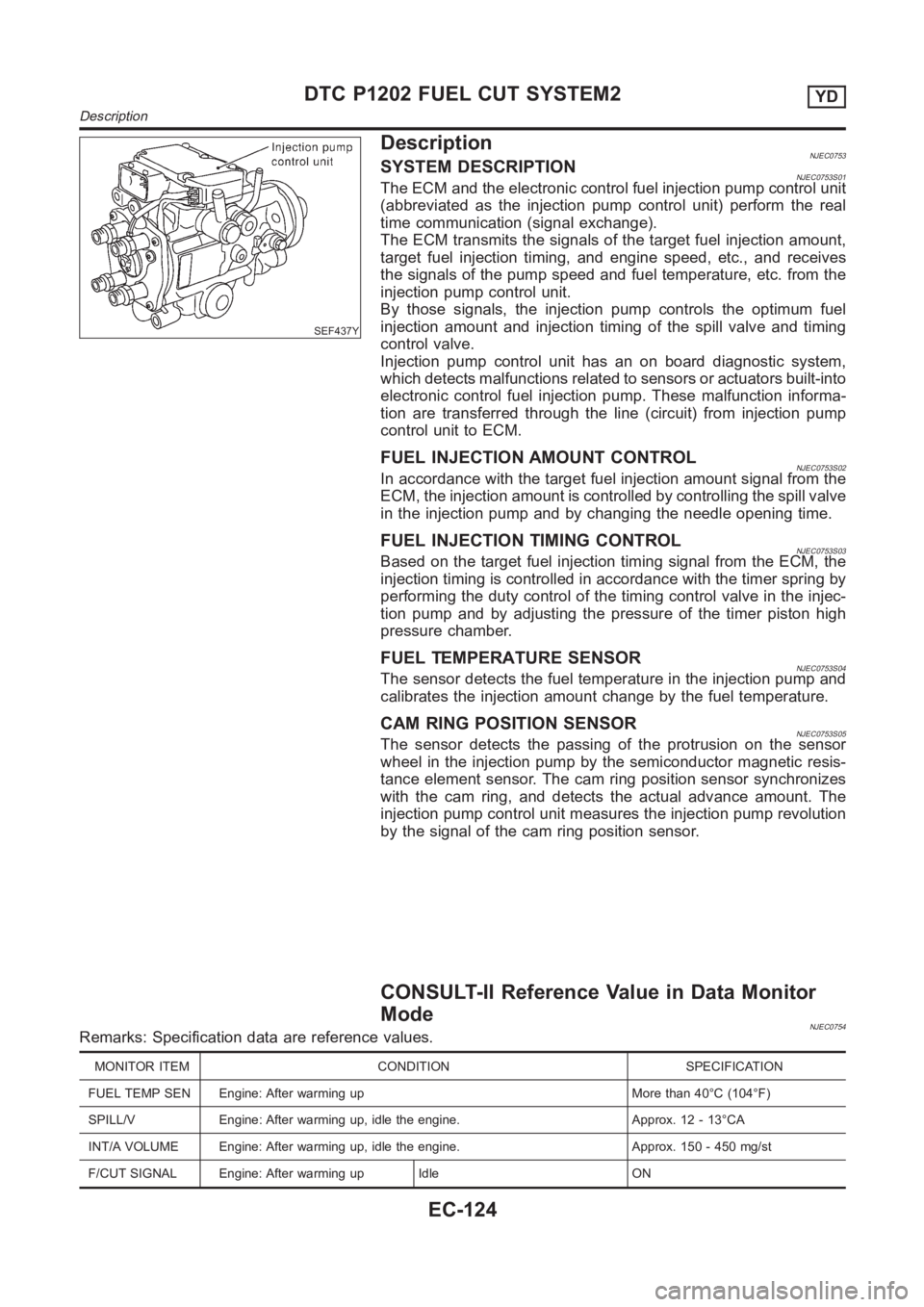
DescriptionNJEC0753SYSTEM DESCRIPTIONNJEC0753S01The ECM and the electronic control fuel injection pump control unit
(abbreviated as the injection pump control unit) perform the real
time communication (signal exchange).
The ECM transmits the signals of the target fuel injection amount,
target fuel injection timing, and engine speed, etc., and receives
the signals of the pump speed and fuel temperature, etc. from the
injection pump control unit.
By those signals, the injection pump controls the optimum fuel
injection amount and injection timing of the spill valve and timing
control valve.
Injection pump control unit has an on board diagnostic system,
which detects malfunctions related to sensors or actuators built-into
electronic control fuel injection pump. These malfunction informa-
tion are transferred through the line (circuit) from injection pump
control unit to ECM.
FUEL INJECTION AMOUNT CONTROLNJEC0753S02In accordance with the target fuel injection amount signal from the
ECM, the injection amount is controlled by controlling the spill valve
in the injection pump and by changing the needle opening time.
FUEL INJECTION TIMING CONTROLNJEC0753S03Based on the target fuel injection timing signal from the ECM, the
injection timing is controlled in accordance with the timer spring by
performing the duty control of the timing control valve in the injec-
tion pump and by adjusting the pressure of the timer piston high
pressure chamber.
FUEL TEMPERATURE SENSORNJEC0753S04The sensor detects the fuel temperature in the injection pump and
calibrates the injection amount change by the fuel temperature.
CAM RING POSITION SENSORNJEC0753S05The sensor detects the passing of the protrusion on the sensor
wheel in the injection pump by the semiconductor magnetic resis-
tance element sensor. The cam ring position sensor synchronizes
with the cam ring, and detects the actual advance amount. The
injection pump control unit measures the injection pump revolution
by the signal of the cam ring position sensor.
CONSULT-II Reference Value in Data Monitor
Mode
NJEC0754Remarks: Specification data are reference values.
MONITOR ITEM CONDITION SPECIFICATION
FUEL TEMP SEN Engine: After warming up More than 40°C (104°F)
SPILL/V Engine: After warming up, idle the engine. Approx. 12 - 13°CA
INT/A VOLUME Engine: After warming up, idle the engine. Approx. 150 - 450 mg/st
F/CUT SIGNAL Engine: After warming up Idle ON
DTC P1202 FUEL CUT SYSTEM2YD
Description
EC-124