2003 NISSAN ALMERA N16 Power
[x] Cancel search: PowerPage 7 of 3189
SEF289H
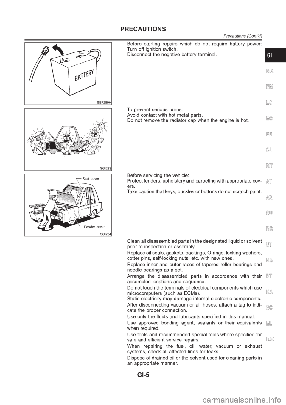
Before starting repairs which do not require battery power:
Turn off ignition switch.
Disconnect the negative battery terminal.
SGI233
To prevent serious burns:
Avoid contact with hot metal parts.
Do not remove the radiator cap when the engine is hot.
SGI234
Before servicing the vehicle:
Protect fenders, upholstery and carpeting with appropriate cov-
ers.
Take caution that keys, buckles or buttons do not scratch paint.
Clean all disassembled parts in the designated liquid or solvent
prior to inspection or assembly.
Replace oil seals, gaskets, packings, O-rings, locking washers,
cotter pins, self-locking nuts, etc. with new ones.
Replace inner and outer races of tapered roller bearings and
needle bearings as a set.
Arrange the disassembled parts in accordance with their
assembled locations and sequence.
Do not touch the terminals of electrical components which use
microcomputers (such as ECMs).
Static electricity may damage internal electronic components.
After disconnecting vacuum or air hoses, attach a tag to indi-
cate the proper connection.
Use only the fluids and lubricants specified in this manual.
Use approved bonding agent, sealants or their equivalents
when required.
Use tools and recommended special tools where specified for
safe and efficient service repairs.
When repairing the fuel, oil, water, vacuum or exhaust
systems, check all affected lines for leaks.
Dispose of drained oil or the solvent used for cleaning parts in
an appropriate manner.
MA
EM
LC
EC
FE
CL
MT
AT
AX
SU
BR
ST
RS
BT
HA
SC
EL
IDX
PRECAUTIONS
Precautions (Cont’d)
GI-5
Page 13 of 3189
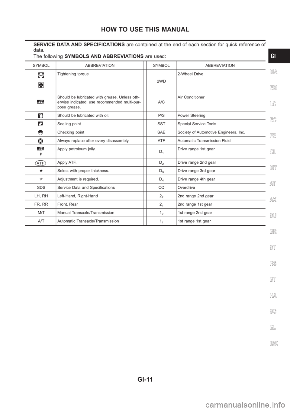
SERVICE DATA AND SPECIFICATIONSare contained at the end of each section for quick reference of
data.
The followingSYMBOLS AND ABBREVIATIONSare used:
SYMBOL ABBREVIATION SYMBOL ABBREVIATION
Tightening torque
2WD2-Wheel Drive
Should be lubricated with grease. Unless oth-
erwise indicated, use recommended multi-pur-
pose grease.A/CAir Conditioner
Should be lubricated with oil. P/S Power Steering
Sealing point SST Special Service Tools
Checking point SAE Society of Automotive Engineers, Inc.
Always replace after every disassembly. ATF Automatic Transmission Fluid
P
Apply petroleum jelly.
D1Drive range 1st gear
Apply ATF. D2Drive range 2nd gear
★Select with proper thickness. D
3Drive range 3rd gear
✩Adjustment is required. D
4Drive range 4th gear
SDS Service Data and Specifications OD Overdrive
LH, RH Left-Hand, Right-Hand 2
22nd range 2nd gear
FR, RR Front, Rear 2
12nd range 1st gear
M/T Manual Transaxle/Transmission 1
21st range 2nd gear
A/T Automatic Transaxle/Transmission 1
11st range 1st gear
MA
EM
LC
EC
FE
CL
MT
AT
AX
SU
BR
ST
RS
BT
HA
SC
EL
IDX
HOW TO USE THIS MANUAL
GI-11
Page 16 of 3189
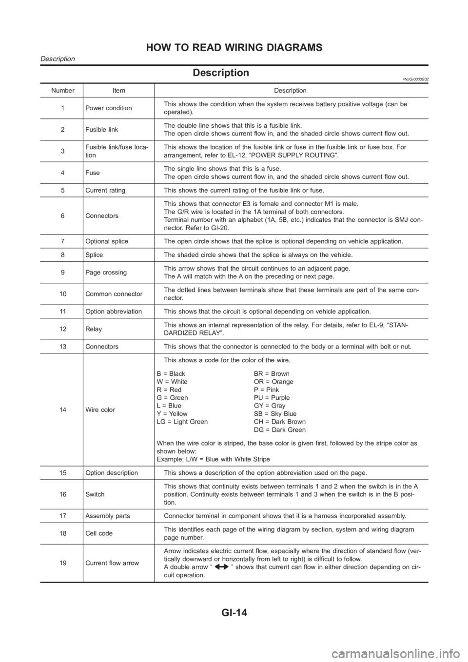
Description=NJGI0003S02
Number Item Description
1 Power conditionThis shows the condition when the system receives battery positive voltage (can be
operated).
2 Fusible linkThe double line shows that this is a fusible link.
The open circle shows current flow in, and the shaded circle shows current flow out.
3Fusible link/fuse loca-
tionThis shows the location of the fusible link or fuse in the fusible link or fusebox.For
arrangement, refer to EL-12, “POWER SUPPLY ROUTING”.
4FuseThe single line shows that this is a fuse.
The open circle shows current flow in, and the shaded circle shows current flow out.
5 Current rating This shows the current rating of the fusible link or fuse.
6 ConnectorsThis shows that connector E3 is female and connector M1 is male.
The G/R wire is located in the 1A terminal of both connectors.
Terminal number with an alphabet (1A, 5B, etc.) indicates that the connector is SMJ con-
nector. Refer to GI-20.
7 Optional splice The open circle shows that the splice is optional depending on vehicle application.
8 Splice The shaded circle shows that the splice is always on the vehicle.
9 Page crossingThis arrow shows that the circuit continues to an adjacent page.
The A will match with the A on the preceding or next page.
10 Common connectorThe dotted lines between terminals show that these terminals are part of thesamecon-
nector.
11 Option abbreviation This shows that the circuit is optional depending on vehicle application.
12 RelayThis shows an internal representation of the relay. For details, refer to EL-9, “STAN-
DARDIZED RELAY”.
13 Connectors This shows that the connector is connected to the body or a terminal with bolt or nut.
14 Wire colorThis shows a code for the color of the wire.
B=Black
W = White
R = Red
G = Green
L = Blue
Y = Yellow
LG = Light GreenBR = Brown
OR = Orange
P = Pink
PU = Purple
GY = Gray
SB = Sky Blue
CH = Dark Brown
DG=DarkGreen
When the wire color is striped, the base color is given first, followed by the stripe color as
shown below:
Example: L/W = Blue with White Stripe
15 Option description This shows a description of the option abbreviationused on the page.
16 SwitchThis shows that continuity exists between terminals 1 and 2 when the switchis in the A
position. Continuity exists between terminals 1 and 3 when the switch is inthe B posi-
tion.
17 Assembly parts Connector terminal in component shows that it is a harness incorporated assembly.
18 Cell codeThis identifies each page of the wiring diagram by section, system and wiring diagram
page number.
19 Current flow arrowArrow indicates electric current flow, especially where the direction ofstandard flow (ver-
tically downward or horizontally from left to right) is difficult to follow.
A double arrow “
” shows that current can flow in either direction depending on cir-
cuit operation.
HOW TO READ WIRING DIAGRAMS
Description
GI-14
Page 17 of 3189
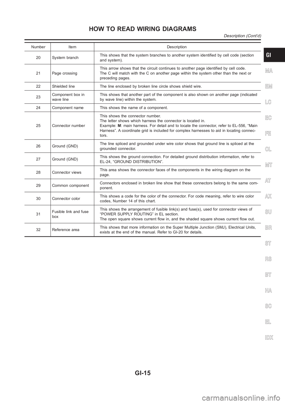
Number Item Description
20 System branchThis shows that the system branches to another system identified by cell code (section
and system).
21 Page crossingThis arrow shows that the circuit continues to another page identified by cell code.
The C will match with the C on another page within the system other than the next or
preceding pages.
22 Shielded line The line enclosed by broken line circle shows shield wire.
23Component box in
wave lineThis shows that another part of the component is also shown on another page (indicated
by wave line) within the system.
24 Component name This shows the name of a component.
25 Connector numberThis shows the connector number.
The letter shows which harness the connector is located in.
Example:M: main harness. For detail and to locate the connector, refer to EL-556, “Main
Harness”. A coordinate grid is included for complex harnesses to aid in locating connec-
tors.
26 Ground (GND)The line spliced and grounded under wire color shows that ground line is spliced at the
grounded connector.
27 Ground (GND)This shows the ground connection. For detailed ground distribution information, refer to
EL-24, “GROUND DISTRIBUTION”.
28 Connector viewsThis area shows the connector faces of the components in the wiring diagramon the
page.
29 Common componentConnectors enclosed in broken line show that these connectors belong to thesamecom-
ponent.
30 Connector colorThis shows a code for the color of the connector. For code meaning, refer to wire color
codes, Number 14 of this chart.
31Fusible link and fuse
boxThis shows the arrangement of fusible link(s) and fuse(s), used for connector views of
“POWER SUPPLY ROUTING” in EL section.
The open square shows current flow in, and the shaded square shows current flow out.
32 Reference areaThis shows that more information on the Super Multiple Junction (SMJ), Electrical Units,
exists at the end of the manual. Refer to GI-20 for details.
MA
EM
LC
EC
FE
CL
MT
AT
AX
SU
BR
ST
RS
BT
HA
SC
EL
IDX
HOW TO READ WIRING DIAGRAMS
Description (Cont’d)
GI-15
Page 24 of 3189
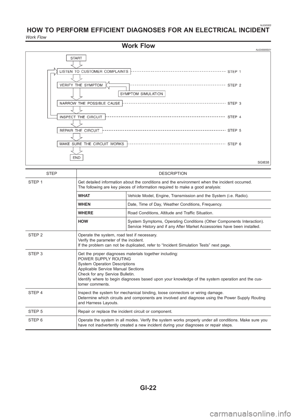
NJGI0005
Work FlowNJGI0005S01
SGI838
STEP DESCRIPTION
STEP 1 Get detailed information about the conditions and the environment when the incident occurred.
The following are key pieces of information required to make a good analysis:
WHATVehicle Model, Engine, Transmission and the System (i.e. Radio).
WHENDate, Time of Day, Weather Conditions, Frequency.
WHERERoad Conditions, Altitude and Traffic Situation.
HOWSystem Symptoms, Operating Conditions (Other Components Interaction).
Service History and if any After Market Accessories have been installed.
STEP 2 Operate the system, road test if necessary.
Verify the parameter of the incident.
If the problem can not be duplicated, refer to “Incident Simulation Tests”next page.
STEP 3 Get the proper diagnoses materials together including:
POWER SUPPLY ROUTING
System Operation Descriptions
Applicable Service Manual Sections
Check for any Service Bulletin.
Identify where to begin diagnoses based upon your knowledge of the system operation and the cus-
tomer comments.
STEP 4 Inspect the system for mechanical binding, loose connectors or wiring damage.
Determine which circuits and components are involved and diagnose using the Power Supply Routing
and Harness Layouts.
STEP 5 Repair or replace the incident circuit or component.
STEP 6 Operate the system in all modes. Verify the system works properly under all conditions. Make sure you
have not inadvertently created a new incident during your diagnoses or repair steps.
HOW TO PERFORM EFFICIENT DIAGNOSES FOR AN ELECTRICAL INCIDENT
Work Flow
GI-22
Page 28 of 3189
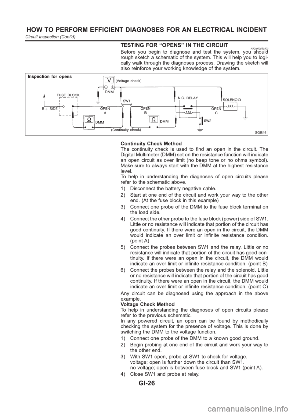
TESTING FOR “OPENS” IN THE CIRCUITNJGI0005S0302Before you begin to diagnose and test the system, you should
rough sketch a schematic of the system. This will help you to logi-
cally walk through the diagnoses process. Drawing the sketch will
also reinforce your working knowledge of the system.
SGI846
Continuity Check Method
The continuity check is used to find an open in the circuit. The
Digital Multimeter (DMM) set on the resistance function will indicate
an open circuit as over limit (no beep tone or no ohms symbol).
Make sure to always start with the DMM at the highest resistance
level.
To help in understanding the diagnoses of open circuits please
refer to the schematic above.
1) Disconnect the battery negative cable.
2) Start at one end of the circuit and work your way to the other
end. (At the fuse block in this example)
3) Connect one probe of the DMM to the fuse block terminal on
the load side.
4) Connect the other probe to the fuse block (power) side of SW1.
Little or no resistance will indicate that portion of the circuit has
good continuity. If there were an open in the circuit, the DMM
would indicate an over limit or infinite resistance condition.
(point A)
5) Connect the probes between SW1 and the relay. Little or no
resistance will indicate that portion of the circuit has good con-
tinuity. If there were an open in the circuit, the DMM would
indicate an over limit or infinite resistance condition. (point B)
6) Connect the probes between the relay and the solenoid. Little
or no resistance will indicate that portion of the circuit has good
continuity. If there were an open in the circuit, the DMM would
indicate an over limit or infinite resistance condition. (point C)
Any circuit can be diagnosed using the approach in the above
example.
Voltage Check Method
To help in understanding the diagnoses of open circuits please
refer to the previous schematic.
In any powered circuit, an open can be found by methodically
checking the system for the presence of voltage. This is done by
switching the DMM to the voltage function.
1) Connect one probe of the DMM to a known good ground.
2) Begin probing at one end of the circuit and work your way to
the other end.
3) With SW1 open, probe at SW1 to check for voltage.
voltage; open is further down the circuit than SW1.
no voltage; open is between fuse block and SW1 (point A).
4) Close SW1 and probe at relay.
HOW TO PERFORM EFFICIENT DIAGNOSES FOR AN ELECTRICAL INCIDENT
Circuit Inspection (Cont’d)
GI-26
Page 29 of 3189
voltage; open is further down the circuit than the relay.
no voltage; open is between SW1 and relay (point B).
5) Close the relay and probe at the solenoid.
voltage; open is further down the circuit than the solenoid.
no voltage; open is between relay and solenoid (point C).
Any powered circuit can be diagnosed using the approach in the
above example.
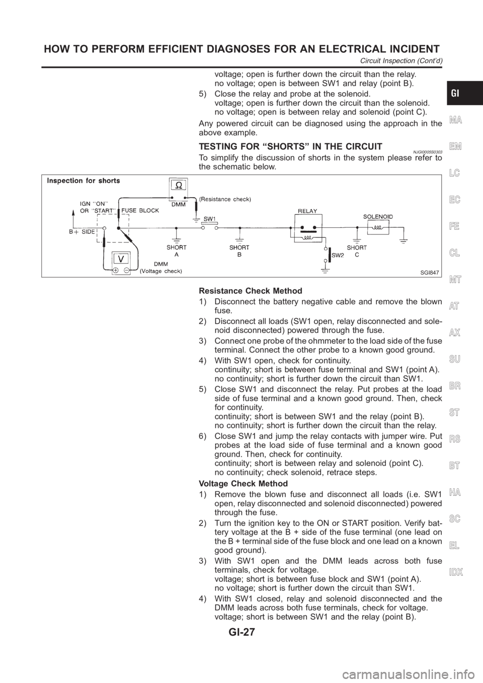
TESTING FOR “SHORTS” IN THE CIRCUITNJGI0005S0303To simplify the discussion of shorts in the system please refer to
the schematic below.
SGI847
Resistance Check Method
1) Disconnect the battery negative cable and remove the blown
fuse.
2) Disconnect all loads (SW1 open, relay disconnected and sole-
noid disconnected) powered through the fuse.
3) Connect one probe of the ohmmeter to the load side of the fuse
terminal. Connect the other probe to a known good ground.
4) With SW1 open, check for continuity.
continuity; short is between fuse terminal and SW1 (point A).
no continuity; short is further down the circuit than SW1.
5) Close SW1 and disconnect the relay. Put probes at the load
side of fuse terminal and a known good ground. Then, check
for continuity.
continuity; short is between SW1 and the relay (point B).
no continuity; short is further down the circuit than the relay.
6) Close SW1 and jump the relay contacts with jumper wire. Put
probes at the load side of fuse terminal and a known good
ground. Then, check for continuity.
continuity; short is between relay and solenoid (point C).
no continuity; check solenoid, retrace steps.
Voltage Check Method
1) Remove the blown fuse and disconnect all loads (i.e. SW1
open, relay disconnected and solenoid disconnected) powered
through the fuse.
2) Turn the ignition key to the ON or START position. Verify bat-
tery voltage at the B + side of the fuse terminal (one lead on
the B + terminal side of the fuse block and one lead on a known
good ground).
3) With SW1 open and the DMM leads across both fuse
terminals, check for voltage.
voltage; short is between fuse block and SW1 (point A).
no voltage; short is further down the circuit than SW1.
4) With SW1 closed, relay and solenoid disconnected and the
DMM leads across both fuse terminals, check for voltage.
voltage; short is between SW1 and the relay (point B).
MA
EM
LC
EC
FE
CL
MT
AT
AX
SU
BR
ST
RS
BT
HA
SC
EL
IDX
HOW TO PERFORM EFFICIENT DIAGNOSES FOR AN ELECTRICAL INCIDENT
Circuit Inspection (Cont’d)
GI-27
Page 30 of 3189
no voltage; short is further down the circuit than the relay.
5) With SW1 closed, relay contacts jumped with fused jumper
wire check for voltage.
voltage; short is down the circuit of the relay or between the
relay and the disconnected solenoid (point C).
no voltage; retrace steps and check power to fuse block.
GROUND INSPECTIONNJGI0005S0304Ground connections are very important to the proper operation of
electrical and electronic circuits. Ground connections are often
exposed to moisture, dirt and other corrosive elements. The corro-
sion (rust) can become an unwanted resistance. This unwanted
resistance can change the way a circuit works.
Electronically controlled circuits are very sensitive to proper
grounding. A loose or corroded ground can drastically affect an
electronically controlled circuit. A poor or corroded ground can eas-
ily affect the circuit. Even when the ground connection looks clean,
there can be a thin film of rust on the surface.
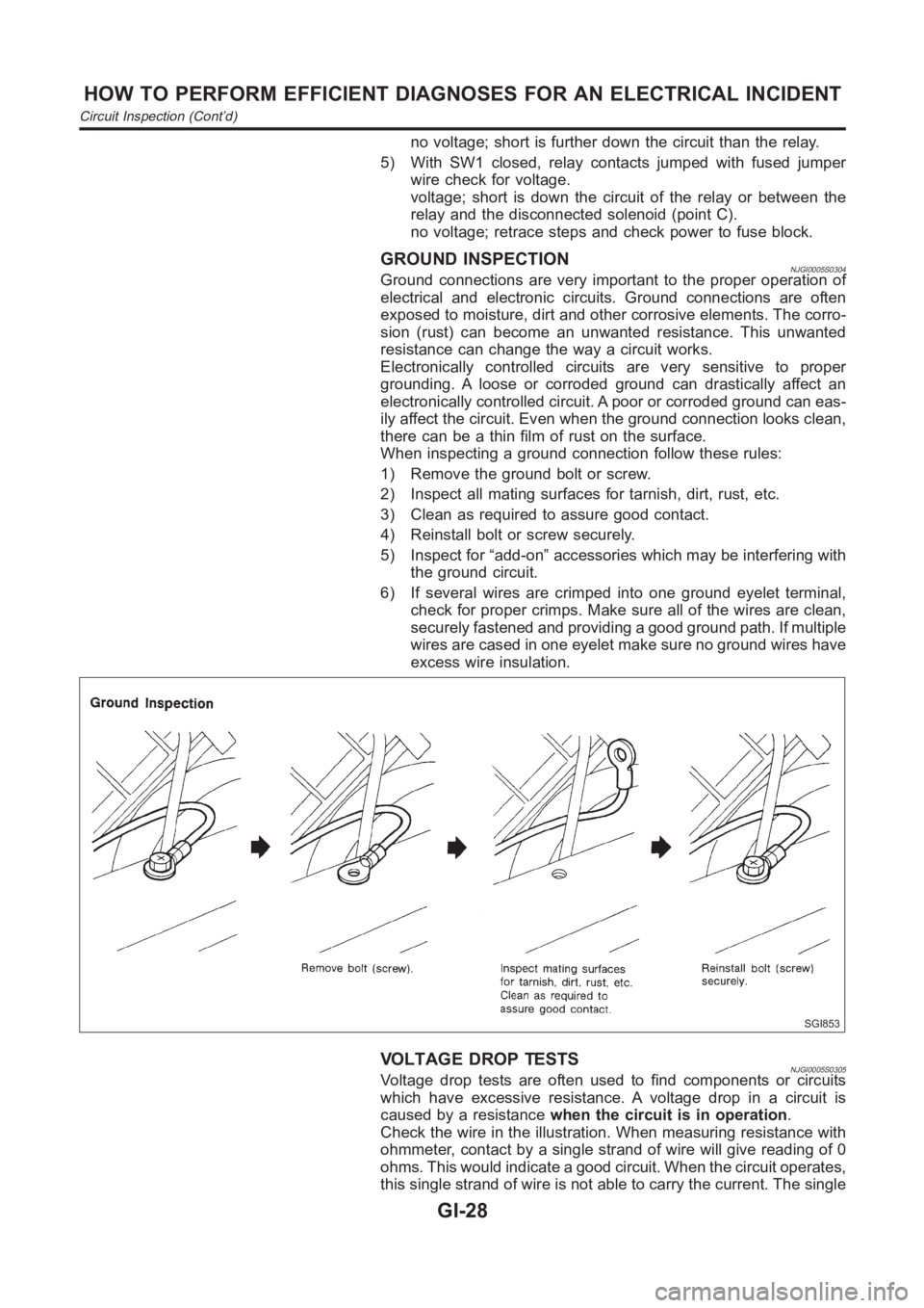
When inspecting a ground connection follow these rules:
1) Remove the ground bolt or screw.
2) Inspect all mating surfaces for tarnish, dirt, rust, etc.
3) Clean as required to assure good contact.
4) Reinstall bolt or screw securely.
5) Inspect for “add-on” accessories which may be interfering with
the ground circuit.
6) If several wires are crimped into one ground eyelet terminal,
check for proper crimps. Make sure all of the wires are clean,
securely fastened and providing a good ground path. If multiple
wires are cased in one eyelet make sure no ground wires have
excess wire insulation.
SGI853
VOLTAGE DROP TESTSNJGI0005S0305Voltage drop tests are often used to find components or circuits
which have excessive resistance. A voltage drop in a circuit is
caused by a resistancewhen the circuit is in operation.
Check the wire in the illustration. When measuring resistance with
ohmmeter, contact by a single strand of wire will give reading of 0
ohms. This would indicate a good circuit. When the circuit operates,
this single strand of wire is not able to carry the current. The single
HOW TO PERFORM EFFICIENT DIAGNOSES FOR AN ELECTRICAL INCIDENT
Circuit Inspection (Cont’d)
GI-28