Page 110 of 3189
EM-32
[QG]
CAMSHAFT
CAMSHAFT
PFP:13001
Removal and InstallationEBS00LQB
CAUTION:
Prior to installation, apply engine oil to the parts marked in the figure.
REMOVAL
1. Remove rocker cover. Refer to EM-29, "ROCKER COVER" .
2. Remove cylinder head front cover.
●Move harness secured to front surface beforehand.
3. Set No. 1 cylinder at TDC of its compression stroke.
a. Remove RH splash cover (integrated with undercover).
b. Rotate crankshaft pulley clockwise and align yellow paint mark
with timing indicator.
PBIC0965E
1. Camshaft bracket 2. Camshaft sprocket (INT) 3. Camshaft sprocket (EXH)
4. Washer 5. Cylinder head front cover 6. Chain tensioner
7. Valve lifter 8. Adjusting shim (If so equipped) 9. Camshaft (EXH)
10. Camshaft (INT)
MBIB0193E
Page 111 of 3189
![NISSAN ALMERA N16 2003 Electronic Repair Manual CAMSHAFT
EM-33
[QG]
C
D
E
F
G
H
I
J
K
L
MA
EM
c. Confirm mating marks stamped on intake and exhaust sprockets
are located as shown.
●If not, rotate crankshaft pulley as shown and align them.
d. Refe NISSAN ALMERA N16 2003 Electronic Repair Manual CAMSHAFT
EM-33
[QG]
C
D
E
F
G
H
I
J
K
L
MA
EM
c. Confirm mating marks stamped on intake and exhaust sprockets
are located as shown.
●If not, rotate crankshaft pulley as shown and align them.
d. Refe](/manual-img/5/57350/w960_57350-110.png)
CAMSHAFT
EM-33
[QG]
C
D
E
F
G
H
I
J
K
L
MA
EM
c. Confirm mating marks stamped on intake and exhaust sprockets
are located as shown.
●If not, rotate crankshaft pulley as shown and align them.
d. Referring to mating marks on intake and exhaust camshaft
sprockets, put paint mating marks on timing chain links.
4. Set intake camshaft sprocket to most advanced position.
CAUTION:
Removal/installation of intake camshaft sprocket is required to maintain most advanced position
because of following reasons. Therefore, follow procedure exactly.
●Sprocket and vane (camshaft in front) rotate and become
offset within specific angle range.
●When engine is stationary, vane is located at most
retarded position. Vane is fixed to sprocket by internal
lock pin. Therefore, it does not rotate.
●If camshaft sprocket mounting bolts are turned under
above circumstance, lock pin will be damaged by lateral
load (shear stress). It may cause non-standard operation.
●Set intake camshaft sprocket to most advanced position as
follows.
NOTE:
“Rotating direction” means direction viewed from engine front side.
CAUTION:
Do not remove chain tensioner before performing this step.
a. Using a wrench, hold hexagonal part so that intake camshaft
does not move.
b. Using an air gun, apply air pressure to intake valve timing con-
trol solenoid valve advanced side oil passage on top surface of
No. 1 camshaft bracket.
●Keep applying air pressure until step “d” is completed.
CAUTION:
●Be careful not to damage oil passage from interference of
air gun tip.
●Thoroughly wipe off oil before applying air pressure.
When applying air pressure, cover around air gun using a rag. Wear protective glasses if neces-
sary.
MBIB0194E
MBIB0195E
MBIB0196E
Compression pressure
: 300 kPa (3.00 bar, 3.06 kg/cm
2 , 43.5 psi) or more
MBIB0197E
Page 125 of 3189
TIMING CHAIN
EM-47
[QG]
C
D
E
F
G
H
I
J
K
L
MA
EM
TIMING CHAINPFP:13028
Removal and InstallationEBS00LQD
CAUTION:
Apply new engine oil to parts marked in illustration before installation.
REMOVAL
1. Place vehicle on lift.
PBIC0971E
1. Cylinder head front cover 2. Camshaft sprocket (INT) 3. Washer
4. Camshaft sprocket (EXH) 5. Chain tensioner 6. Chain slack guide
7. O-ring 8. Power steering pump adjusting bar 9. Crankshaft pulley
10. Front oil seal 11. Front cover 12. Chain tension guide
13. Dowel pin 14. Timing chain 15. Oil pump drive spacer
16. Crankshaft sprocket 17. O-ring (with collar) 18. Auxiliary bolt of cylinder head
Page 129 of 3189
![NISSAN ALMERA N16 2003 Electronic Repair Manual TIMING CHAIN
EM-51
[QG]
C
D
E
F
G
H
I
J
K
L
MA
EM
30. Remove timing chain, timing chain slack guide and tension guide.
31. Remove crankshaft sprocket.
INSPECTION AFTER REMOVAL
Timing Chain
Check timi NISSAN ALMERA N16 2003 Electronic Repair Manual TIMING CHAIN
EM-51
[QG]
C
D
E
F
G
H
I
J
K
L
MA
EM
30. Remove timing chain, timing chain slack guide and tension guide.
31. Remove crankshaft sprocket.
INSPECTION AFTER REMOVAL
Timing Chain
Check timi](/manual-img/5/57350/w960_57350-128.png)
TIMING CHAIN
EM-51
[QG]
C
D
E
F
G
H
I
J
K
L
MA
EM
30. Remove timing chain, timing chain slack guide and tension guide.
31. Remove crankshaft sprocket.
INSPECTION AFTER REMOVAL
Timing Chain
Check timing chain for cracks or serious wear. If a malfunction is
detected, replace it.
INSTALLATION
CAUTION:
●Use a scraper to completely remove all liquid gasket adhering to mounting surface. De-grease and
clean with white gasoline.
●After installation, wipe off any protruding liquid gasket.
1. Install timing chain and its related parts with the following procedure:
●For aligning positions for each sprocket and timing chain, and
installed condition of their related parts, refer to figure.
●Install each sprocket with its mating mark facing engine front
side.
a. Install timing chain and crankshaft sprocket.
●Make sure that crankshaft key points straight up (No.1 cylin-
der is at TDC).
●Hook timing chain on front end of camshaft so that it will not
fall off.
b. Install timing chain slack guide and tension guide.
c. Install camshaft sprocket. Refer to EM-35, "
INSTALLATION" .
d. Install chain tensioner. Refer to EM-35, "
INSTALLATION" .
e. Make sure again that mating marks are properly aligned.
f. Temporarily install oil pump drive spacer, crankshaft pulley, and crankshaft pulley mounting bolt so that
crankshaft can be rotated.
g. Rotate crankshaft clockwise several times to make sure it rotates normally. Refer to EM-35, "
INSTALLA-
TION" .
h. Rotate crankshaft clockwise several times, and check that there is no unusual condition.
i. Remove parts temporarily installed in step f.
PBIC0282E
KBIA1398E
Page 138 of 3189
EM-60
[QG]
CYLINDER HEAD
3. Tighten cylinder auxiliary bolts (11) to (14) in numerical order
shown in figure.
●Pay attention to shank length under bolt head. [11: 20 mm
(0.79 in), 12 - 14: 25 mm (0.98 in)]
Disassembly and AssemblyEBS00LQJ
CAUTION:
●When installing camshafts, chain tensioners, oil seals or other sliding parts, lubricate contacting
surface with new engine oil.
●Apply new engine oil to threads and seat surface when installing cylinder head, camshaft
sprocket, crankshaft pulley and camshaft bracket.
●Attach tags to valve lifters so as not to mix them up.
DISASSEMBLY
1. Remove adjusting shim (if so equipped) and valve lifter.
●Confirm installation point.
SEM900F
PBIC0973E
1. Cylinder head 2. Valve (INT) 3. Valve (EXH)
4. Valve seat 5. Engine coolant temperature sensor 6. Copper washer
7. Spark plug tube 8. Spark plug
Page 204 of 3189

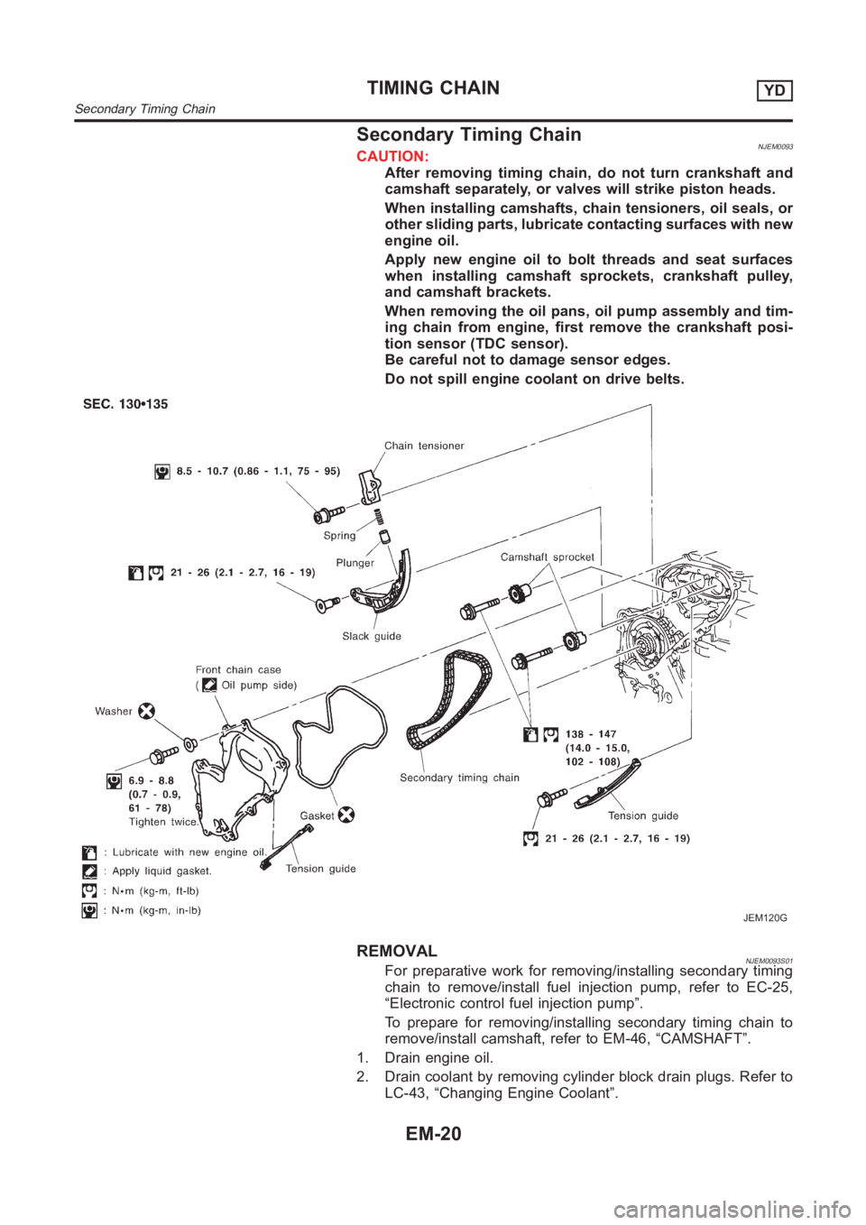
Secondary Timing ChainNJEM0093CAUTION:
After removing timing chain, do not turn crankshaft and
camshaft separately, or valves will strike piston heads.
When installing camshafts, chain tensioners, oil seals, or
other sliding parts, lubricate contacting surfaces with new
engine oil.
Apply new engine oil to bolt threads and seat surfaces
when installing camshaft sprockets, crankshaft pulley,
and camshaft brackets.
When removing the oil pans, oil pump assembly and tim-
ing chain from engine, first remove the crankshaft posi-
tion sensor (TDC sensor).
Be careful not to damage sensor edges.
Do not spill engine coolant on drive belts.
JEM120G
REMOVALNJEM0093S01For preparative work for removing/installing secondary timing
chain to remove/install fuel injection pump, refer to EC-25,
“Electronic control fuel injection pump”.
To prepare for removing/installing secondary timing chain to
remove/install camshaft, refer to EM-46, “CAMSHAFT”.
1. Drain engine oil.
2. Drain coolant by removing cylinder block drain plugs. Refer to
LC-43, “Changing Engine Coolant”.
TIMING CHAINYD
Secondary Timing Chain
EM-20
Page 205 of 3189

JEM121G
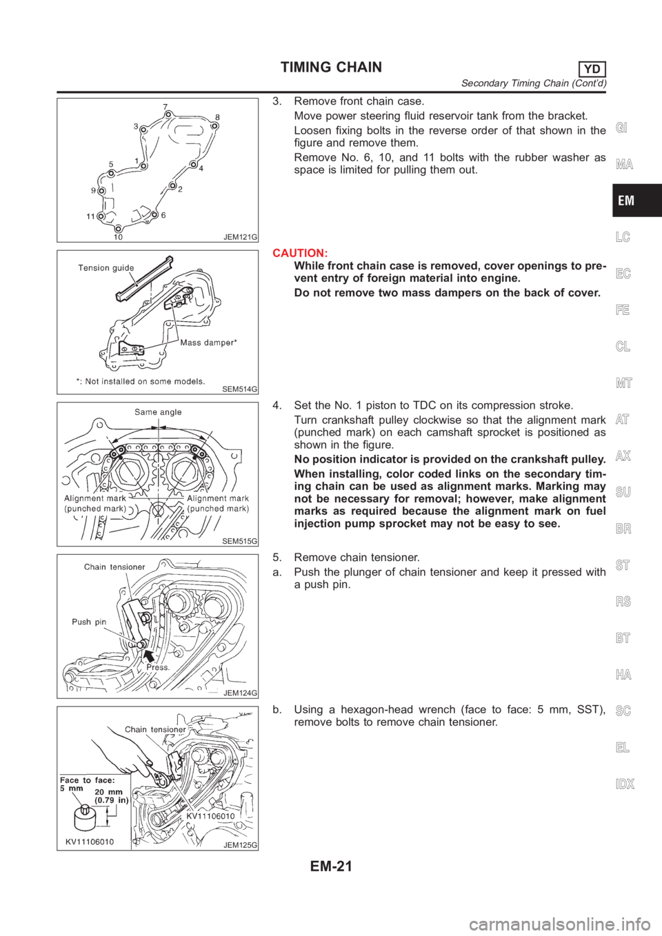
3. Remove front chain case.
Move power steering fluid reservoir tank from the bracket.
Loosen fixing bolts in the reverse order of that shown in the
figure and remove them.
Remove No. 6, 10, and 11 bolts with the rubber washer as
space is limited for pulling them out.
SEM514G
CAUTION:
While front chain case is removed, cover openings to pre-
vent entry of foreign material into engine.
Do not remove two mass dampers on the back of cover.
SEM515G
4. Set the No. 1 piston to TDC on its compression stroke.
Turn crankshaft pulley clockwise so that the alignment mark
(punched mark) on each camshaft sprocket is positioned as
shown in the figure.
No position indicator is provided on the crankshaft pulley.
When installing, color coded links on the secondary tim-
ing chain can be used as alignment marks. Marking may
not be necessary for removal; however, make alignment
marks as required because the alignment mark on fuel
injection pump sprocket may not be easy to see.
JEM124G
5. Remove chain tensioner.
a. Push the plunger of chain tensioner and keep it pressed with
a push pin.
JEM125G
b. Using a hexagon-head wrench (face to face: 5 mm, SST),
remove bolts to remove chain tensioner.
GI
MA
LC
EC
FE
CL
MT
AT
AX
SU
BR
ST
RS
BT
HA
SC
EL
IDX
TIMING CHAINYD
Secondary Timing Chain (Cont’d)
EM-21
Page 230 of 3189

CAUTION:
When installing camshafts, chain tensioners, oil seals, or
other sliding parts, lubricate contacting surfaces with new
engine oil.
Apply new engine oil to threads and seat surfaces when
installing cylinder head, camshaft sprocket, crankshaft
pulley, and camshaft bracket.
Attach tags to valve lifters so as not to mix them up.
RemovalNJEM0063PREPARATIVE WORKNJEM0063S011. Drain engine coolant. Refer to LC-43, “Changing Engine Cool-
ant”.
2. Remove exhaust manifold. Refer to EM-38, “Removal”.
3. Remove intake manifold. Refer to EM-34, “Removal”.
Apply paint to camshaft sprockets for alignment during
installation.
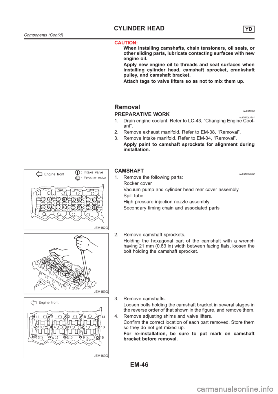
JEM152G
CAMSHAFTNJEM0063S021. Remove the following parts:
Rocker cover
Vacuum pump and cylinder head rear cover assembly
Spill tube
High pressure injection nozzle assembly
Secondary timing chain and associated parts
JEM159G
2. Remove camshaft sprockets.
Holding the hexagonal part of the camshaft with a wrench
having 21 mm (0.83 in) width between facing flats, loosen the
bolt holding the camshaft sprocket.
JEM160G
3. Remove camshafts.
Loosen bolts holding the camshaft bracket in several stages in
the reverse order of that shown in the figure, and remove them.
4. Remove adjusting shims and valve lifters.
Confirm the correct location of each part removed. Store them
so they do not get mixed up.
For re-installation, be sure to put mark on camshaft
bracket before removal.
CYLINDER HEADYD
Components (Cont’d)
EM-46