2003 NISSAN ALMERA N16 ABS connector
[x] Cancel search: ABS connectorPage 357 of 3189
![NISSAN ALMERA N16 2003 Electronic Repair Manual ENGINE CONTROL SYSTEM
EC-27
[QG (WITH EURO-OBD)]
C
D
E
F
G
H
I
J
K
L
MA
EC
Fuel Cut Control (at No Load and High Engine Speed)EBS00K38
INPUT/OUTPUT SIGNAL CHART
*1: This signal is sent to the ECM thro NISSAN ALMERA N16 2003 Electronic Repair Manual ENGINE CONTROL SYSTEM
EC-27
[QG (WITH EURO-OBD)]
C
D
E
F
G
H
I
J
K
L
MA
EC
Fuel Cut Control (at No Load and High Engine Speed)EBS00K38
INPUT/OUTPUT SIGNAL CHART
*1: This signal is sent to the ECM thro](/manual-img/5/57350/w960_57350-356.png)
ENGINE CONTROL SYSTEM
EC-27
[QG (WITH EURO-OBD)]
C
D
E
F
G
H
I
J
K
L
MA
EC
Fuel Cut Control (at No Load and High Engine Speed)EBS00K38
INPUT/OUTPUT SIGNAL CHART
*1: This signal is sent to the ECM through CAN communication line.
SYSTEM DESCRIPTION
If the engine speed is above 3,950 rpm with no load (for example, in neutral and engine speed over 3,950
rpm) fuel will be cut off after some time. The exact time when the fuel is cut off varies based on engine speed.
Fuel cut will operate until the engine speed reaches 1,500 rpm, then fuel cut is cancelled.
NOTE:
This function is different from deceleration control listed under “Multiport Fuel Injection (MFI) System”, EC-23
.
CAN CommunicationEBS00K39
SYSTEM DESCRIPTION
CAN (Controller Area Network) is a serial communication line for real time application. It is an on-vehicle mul-
tiplex communication line with high data communication speed and excellent error detection ability. Many elec-
tronic control units are equipped onto a vehicle, and each control unit shares information and links with other
control units during operation (not independent). In CAN communication, control units are connected with 2
communication lines (CAN H line, CAN L line) allowing a high rate of information transmission with less wiring.
Each control unit transmits/receives data but selectively reads required data only.
CAN COMMUNICATION UNIT
×:ApplicableSensor Input Signal to ECM ECM Function Actuator
Park/neutral position (PNP) switch Neutral position
Fuel cut control Fuel injectors Throttle position sensor Throttle position
Accelerator pedal position sensor Accelerator pedal position
Engine coolant temperature sensor Engine coolant temperature
Crankshaft position sensor (POS)
Camshaft position sensor (PHASE)Engine speed
Vehicle speed signal
*1Vehicle speed
Body type Sedan/ 5DH/B/ 3DH/B
Axle2WD
Engine QG18DE QG15DE/QG18DE
Transmission A/T M/T
Brake controlABS
CAN communication unit
ECM××
TCM×
Smart entrance control unit××
Data link connector××
Combination meter××
CAN communication type EC-28, "
Type 1"EC-29, "Ty p e 2"
Page 587 of 3189
![NISSAN ALMERA N16 2003 Electronic Repair Manual DTC P0500 VSS
EC-257
[QG (WITH EURO-OBD)]
C
D
E
F
G
H
I
J
K
L
MA
EC
DTC P0500 VSSPFP:32702
DescriptionEBS00K8V
NOTE:
If DTC P0500 is displayed with DTC U1000 or U1001, first perform the trouble diagno NISSAN ALMERA N16 2003 Electronic Repair Manual DTC P0500 VSS
EC-257
[QG (WITH EURO-OBD)]
C
D
E
F
G
H
I
J
K
L
MA
EC
DTC P0500 VSSPFP:32702
DescriptionEBS00K8V
NOTE:
If DTC P0500 is displayed with DTC U1000 or U1001, first perform the trouble diagno](/manual-img/5/57350/w960_57350-586.png)
DTC P0500 VSS
EC-257
[QG (WITH EURO-OBD)]
C
D
E
F
G
H
I
J
K
L
MA
EC
DTC P0500 VSSPFP:32702
DescriptionEBS00K8V
NOTE:
If DTC P0500 is displayed with DTC U1000 or U1001, first perform the trouble diagnosis for DTC U1000,
U1001. Refer to EC-116, "
DTC U1000, U1001 CAN COMMUNICATION LINE" .
The vehicle speed signal is sent from vehicle speed sensor (models without ABS) or ABS actuator and electric
unit (control unit) (models with ABS) to combination meter. The combination meter then sends a signal to the
ECM through CAN communication line.
On Board Diagnosis LogicEBS00K8W
DTC Confirmation ProcedureEBS00K8X
CAUTION:
Always drive vehicle at a safe speed.
NOTE:
If “DTC Confirmation Procedure” has been previously conducted, always turn ignition switch “OFF” and wait at
least 10 seconds before conducting the next test.
TESTING CONDITION:
Steps 1 and 2 may be conducted with the drive wheels lifted in the shop or by driving the vehicle. If a
road test is expected to be easier, it is unnecessary to lift the vehicle.
WITH CONSULT-II
1. Start engine.
2. Read “VHCL SPEED SE” in “DATA MONITOR” mode with CONSULT-II. The vehicle speed on CONSULT-
II should exceed 10 km/h (6 MPH) when rotating wheels with suitable gear position.
If NG, go to EC-259, "
Diagnostic Procedure" .
If OK, go to following step.
3. Select “DATA MONITOR” mode with CONSULT-II.
4. Warm engine up to normal operating temperature.
5. Maintain the following conditions for at least 60 consecutive sec-
onds.
6. If 1st trip DTC is detected, go to EC-259, "
Diagnostic Procedure" .
DTC No. Trouble diagnosis name DTC detecting condition Possible cause
P0500
0500Vehicle speed sensorThe almost 0 km/h (0 MPH) signal from
vehicle speed sensor is sent to ECM
even when vehicle is being driven.
●Harness or connectors
(The vehicle speed sensor circuit is open or
shorted)
●Harness or connectors
(The CAN communication line is open or
shorted.)
●Vehicle speed sensor (models without ABS)
●ABS actuator and electric unit (control unit)
(models with ABS)
●Combination meter
ENG SPEED More than 2,400 rpm (QG15DE models)
More then 2,100 rpm (QG18DE A/T models)
More then 2,700 rpm (QG18DE M/T models)
COOLAN TEMP/S More than 70°C (158°F)
B/FUEL SCHDL More than 4.6 msec (QG15DE models)
More than 5.2 msec (QG18DE A/T models)
More than 4.3 msec (QG18DE M/T models
Selector lever Suitable position
PW/ST SIGNAL OFF
SEF196Y
Page 751 of 3189
![NISSAN ALMERA N16 2003 Electronic Repair Manual ENGINE CONTROL SYSTEM
EC-421
[QG (WITHOUT EURO-OBD)]
C
D
E
F
G
H
I
J
K
L
MA
EC
Fuel Cut Control (at No Load and High Engine Speed)EBS00KEF
INPUT/OUTPUT SIGNAL CHART
*1: This signal is sent to the ECM NISSAN ALMERA N16 2003 Electronic Repair Manual ENGINE CONTROL SYSTEM
EC-421
[QG (WITHOUT EURO-OBD)]
C
D
E
F
G
H
I
J
K
L
MA
EC
Fuel Cut Control (at No Load and High Engine Speed)EBS00KEF
INPUT/OUTPUT SIGNAL CHART
*1: This signal is sent to the ECM](/manual-img/5/57350/w960_57350-750.png)
ENGINE CONTROL SYSTEM
EC-421
[QG (WITHOUT EURO-OBD)]
C
D
E
F
G
H
I
J
K
L
MA
EC
Fuel Cut Control (at No Load and High Engine Speed)EBS00KEF
INPUT/OUTPUT SIGNAL CHART
*1: This signal is sent to the ECM through CAN communication line.
SYSTEM DESCRIPTION
If the engine speed is above 3,950 rpm with no load (for example, in neutral and engine speed over 3,950
rpm) fuel will be cut off after some time. The exact time when the fuel is cut off varies based on engine speed.
Fuel cut will operate until the engine speed reaches 1,500 rpm, then fuel cut is cancelled.
NOTE:
This function is different from deceleration control listed under “Multiport Fuel Injection (MFI) System”, EC-417
.
CAN CommunicationEBS00KEG
SYSTEM DESCRIPTION
CAN (Controller Area Network) is a serial communication line for real time application. It is an on-vehicle mul-
tiplex communication line with high data communication speed and excellent error detection ability. Many elec-
tronic control units are equipped onto a vehicle, and each control unit shares information and links with other
control units during operation (not independent). In CAN communication, control units are connected with 2
communication lines (CAN H line, CAN L line) allowing a high rate of information transmission with less wiring.
Each control unit transmits/receives data but selectively reads required data only.
CAN COMMUNICATION UNIT
×:ApplicableSensor Input Signal to ECM ECM function Actuator
Park/neutral position (PNP) switch Neutral position
Fuel cut control Fuel injectors Throttle position sensor Throttle position
Accelerator pedal position sensor Accelerator pedal position
Engine coolant temperature sensor Engine coolant temperature
Crankshaft position sensor (POS)
Camshaft position sensor (PHASE)Engine speed
Vehicle speed signal
*1Vehicle speed
Body type Sedan/ 5DH/B/ 3DH/B
Axle2WD
Engine QG18DE QG15DE/QG18DE
Transmission A/T M/T
Brake controlABS
CAN communication unit
ECM××
TCM×
Data link connector××
Smart entrance control unit××
Combination meter××
CAN communication type EC-422, "
Ty p e 1"EC-423, "Type 2"
Page 1162 of 3189

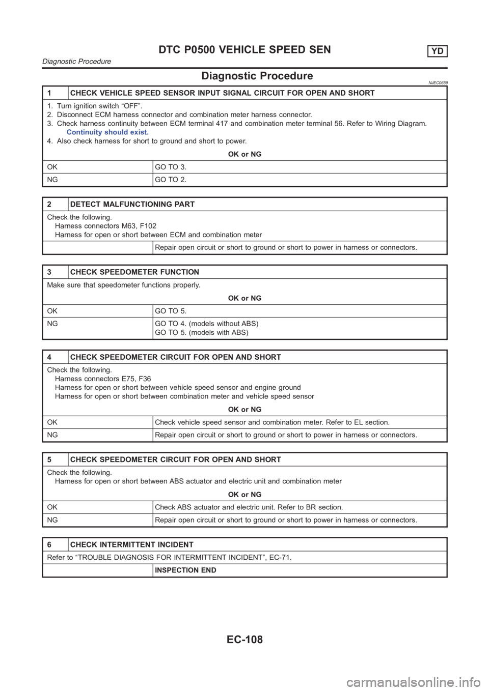
Diagnostic ProcedureNJEC0659
1 CHECK VEHICLE SPEED SENSOR INPUT SIGNAL CIRCUIT FOR OPEN AND SHORT
1. Turn ignition switch “OFF”.
2. Disconnect ECM harness connector and combination meter harness connector.
3. Check harness continuity between ECM terminal 417 and combination meter terminal 56. Refer to Wiring Diagram.
Continuity should exist.
4. Also check harness for short to ground and short to power.
OK or NG
OK GO TO 3.
NG GO TO 2.
2 DETECT MALFUNCTIONING PART
Check the following.
Harness connectors M63, F102
Harness for open or short between ECM and combination meter
Repair open circuit or short to ground or short to power in harness or connectors.
3 CHECK SPEEDOMETER FUNCTION
Make sure that speedometer functions properly.
OK or NG
OK GO TO 5.
NG GO TO 4. (models without ABS)
GO TO 5. (models with ABS)
4 CHECK SPEEDOMETER CIRCUIT FOR OPEN AND SHORT
Check the following.
Harness connectors E75, F36
Harness for open or short between vehicle speed sensor and engine ground
Harness for open or short between combination meter and vehicle speed sensor
OK or NG
OK Check vehicle speed sensor and combination meter. Refer to EL section.
NG Repair open circuit or short to ground or short to power in harness or connectors.
5 CHECK SPEEDOMETER CIRCUIT FOR OPEN AND SHORT
Check the following.
Harness for open or short between ABS actuator and electric unit and combination meter
OK or NG
OK Check ABS actuator and electric unit. Refer to BR section.
NG Repair open circuit or short to ground or short to power in harness or connectors.
6 CHECK INTERMITTENT INCIDENT
Refer to “TROUBLE DIAGNOSIS FOR INTERMITTENT INCIDENT”, EC-71.
INSPECTION END
DTC P0500 VEHICLE SPEED SENYD
Diagnostic Procedure
EC-108
Page 1170 of 3189

SEC220B
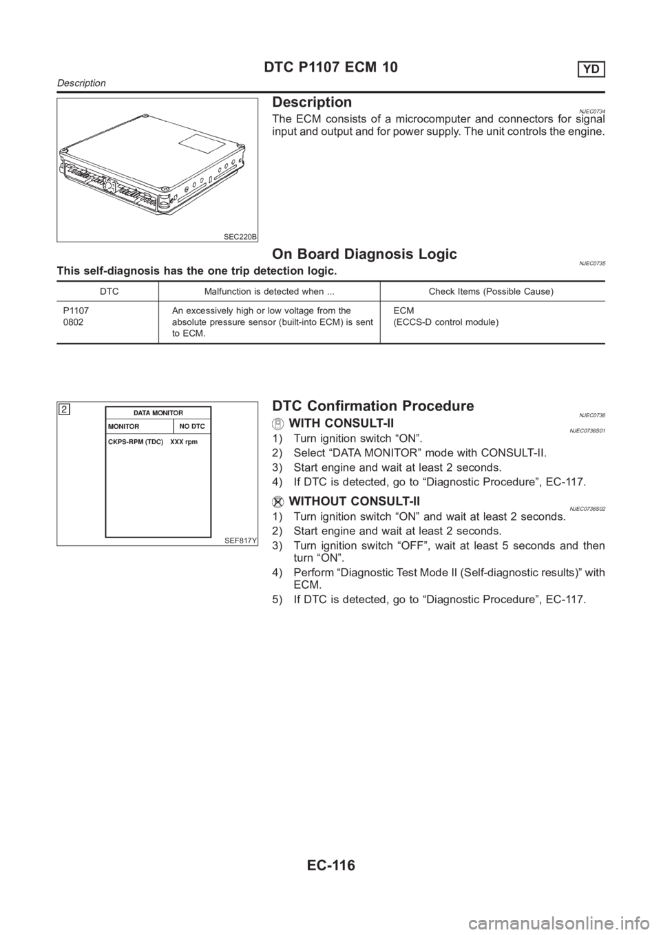
DescriptionNJEC0734The ECM consists of a microcomputer and connectors for signal
input and output and for power supply. The unit controls the engine.
On Board Diagnosis LogicNJEC0735This self-diagnosis has the one trip detection logic.
DTC Malfunction is detected when ... Check Items (Possible Cause)
P1107
0802An excessively high or low voltage from the
absolute pressure sensor (built-into ECM) is sent
to ECM.ECM
(ECCS-D control module)
SEF817Y
DTC Confirmation ProcedureNJEC0736WITH CONSULT-IINJEC0736S011) Turn ignition switch “ON”.
2) Select “DATA MONITOR” mode with CONSULT-II.
3) Start engine and wait at least 2 seconds.
4) If DTC is detected, go to “Diagnostic Procedure”, EC-117.
WITHOUT CONSULT-IINJEC0736S021) Turn ignition switch “ON” and wait at least 2 seconds.
2) Start engine and wait at least 2 seconds.
3) Turn ignition switch “OFF”, wait at least 5 seconds and then
turn “ON”.
4) Perform “Diagnostic Test Mode II (Self-diagnostic results)” with
ECM.
5) If DTC is detected, go to “Diagnostic Procedure”, EC-117.
DTC P1107 ECM 10YD
Description
EC-116
Page 1287 of 3189

JFE613A
SFE600A
SFE601A
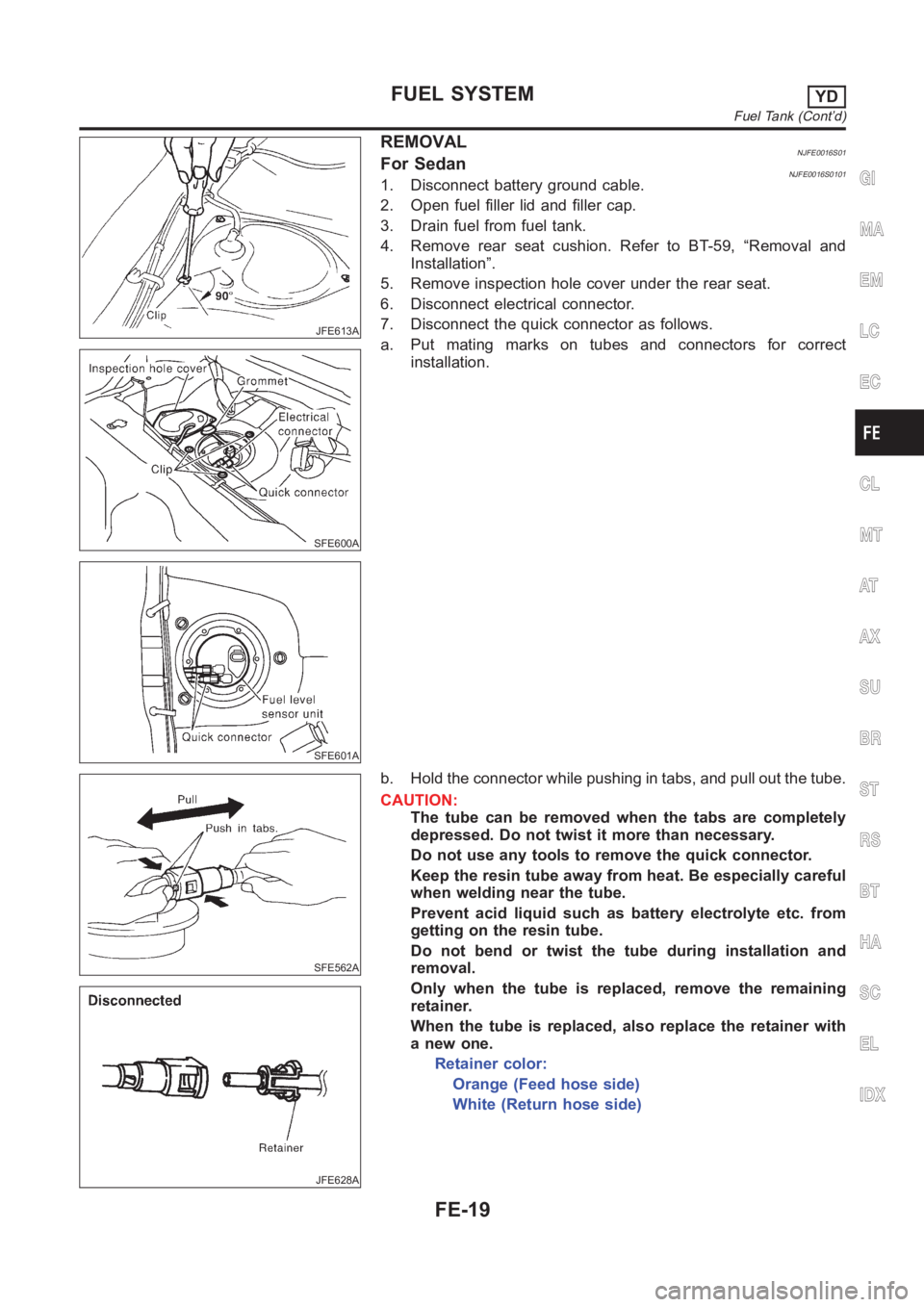
REMOVALNJFE0016S01For SedanNJFE0016S01011. Disconnect battery ground cable.
2. Open fuel filler lid and filler cap.
3. Drain fuel from fuel tank.
4. Remove rear seat cushion. Refer to BT-59, “Removal and
Installation”.
5. Remove inspection hole cover under the rear seat.
6. Disconnect electrical connector.
7. Disconnect the quick connector as follows.
a. Put mating marks on tubes and connectors for correct
installation.
SFE562A
JFE628A
b. Hold the connector while pushing in tabs, and pull out the tube.
CAUTION:
The tube can be removed when the tabs are completely
depressed. Do not twist it more than necessary.
Do not use any tools to remove the quick connector.
Keep the resin tube away from heat. Be especially careful
when welding near the tube.
Prevent acid liquid such as battery electrolyte etc. from
getting on the resin tube.
Do not bend or twist the tube during installation and
removal.
Only when the tube is replaced, remove the remaining
retainer.
When the tube is replaced, also replace the retainer with
a new one.
Retainer color:
Orange (Feed hose side)
White (Return hose side)
GI
MA
EM
LC
EC
CL
MT
AT
AX
SU
BR
ST
RS
BT
HA
SC
EL
IDX
FUEL SYSTEMYD
Fuel Tank (Cont’d)
FE-19
Page 1289 of 3189

JFE613A
SFE639A
SFE640A
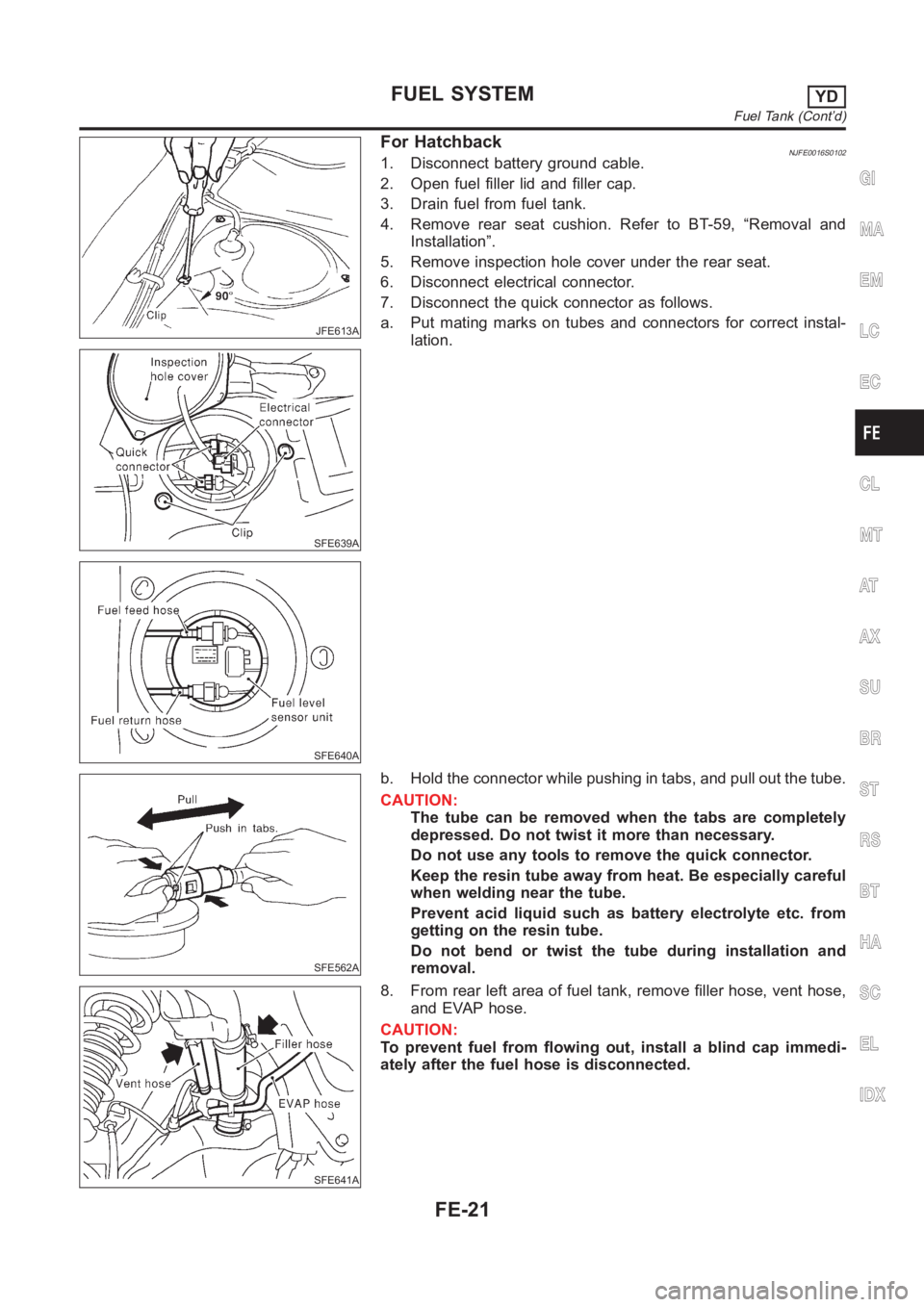
For HatchbackNJFE0016S01021. Disconnect battery ground cable.
2. Open fuel filler lid and filler cap.
3. Drain fuel from fuel tank.
4. Remove rear seat cushion. Refer to BT-59, “Removal and
Installation”.
5. Remove inspection hole cover under the rear seat.
6. Disconnect electrical connector.
7. Disconnect the quick connector as follows.
a. Put mating marks on tubes and connectors for correct instal-
lation.
SFE562A
b. Hold the connector while pushing in tabs, and pull out the tube.
CAUTION:
The tube can be removed when the tabs are completely
depressed. Do not twist it more than necessary.
Do not use any tools to remove the quick connector.
Keep the resin tube away from heat. Be especially careful
when welding near the tube.
Prevent acid liquid such as battery electrolyte etc. from
getting on the resin tube.
Do not bend or twist the tube during installation and
removal.
SFE641A
8. From rear left area of fuel tank, remove filler hose, vent hose,
and EVAP hose.
CAUTION:
To prevent fuel from flowing out, install a blind cap immedi-
ately after the fuel hose is disconnected.
GI
MA
EM
LC
EC
CL
MT
AT
AX
SU
BR
ST
RS
BT
HA
SC
EL
IDX
FUEL SYSTEMYD
Fuel Tank (Cont’d)
FE-21
Page 1565 of 3189
![NISSAN ALMERA N16 2003 Electronic Repair Manual CAN COMMUNICATION
AT-109
[EURO-OBD]
D
E
F
G
H
I
J
K
L
MA
B
AT
CAN COMMUNICATIONPFP:23710
System DescriptionECS007O2
CAN (Controller Area Network) is a serial communication line for real time applicati NISSAN ALMERA N16 2003 Electronic Repair Manual CAN COMMUNICATION
AT-109
[EURO-OBD]
D
E
F
G
H
I
J
K
L
MA
B
AT
CAN COMMUNICATIONPFP:23710
System DescriptionECS007O2
CAN (Controller Area Network) is a serial communication line for real time applicati](/manual-img/5/57350/w960_57350-1564.png)
CAN COMMUNICATION
AT-109
[EURO-OBD]
D
E
F
G
H
I
J
K
L
MA
B
AT
CAN COMMUNICATIONPFP:23710
System DescriptionECS007O2
CAN (Controller Area Network) is a serial communication line for real time application. It is an on-vehicle mul-
tiplex communication line with high data communication speed and excellent error detection ability. Many elec-
tronic control units are equipped onto a vehicle, and each control unit shares information and links with other
control units during operation (not independent). In CAN communication, control units are connected with 2
communication lines (CAN H line, CAN L line) allowing a high rate of information transmission with less wiring.
Each control unit transmits/receives data but selectively reads required data only.
CAN Communication UnitECS007O3
×:Applicable
TYPE1
System diagram
Input/output signal chart
T: Transmit R: Receive Body type Sedan/ 5DH/B/ 3DH/B
Axle2WD
Engine QG18DE QG15DE/QG18DE
Transmission A/T M/T
Brake controlABS
CAN communication unit
ECM××
TCM×
Smart entrance control unit××
Data link connector××
Combination meter××
CAN communication type AT-109, "
TYPE1"AT-110, "TYPE 2"
SEL825Y
Signals ECM TCMSmart entrance
control unitCombination meter
Engine speed signal T R
Brake switch signal R T
Rear window defogger signal R T
Heater fan switch signal R T
Air conditioner switch signal R T
MI signal T R
Current gear position signal T R
Engine coolant temperature signal T R
Fuel consumption signal T R