2003 NISSAN ALMERA N16 Super
[x] Cancel search: SuperPage 17 of 3189
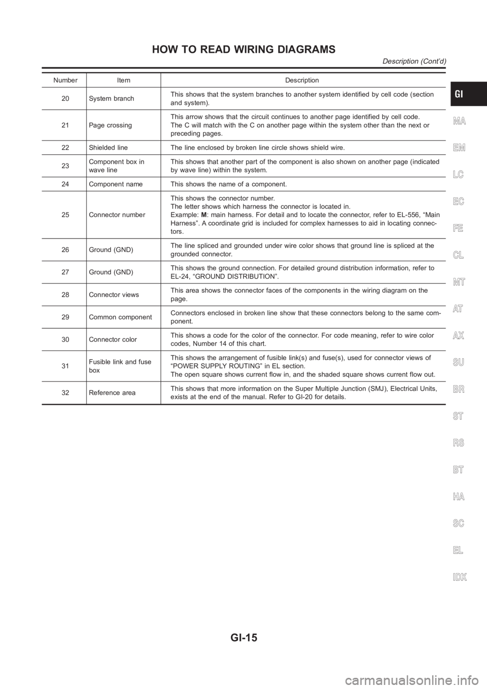
Number Item Description
20 System branchThis shows that the system branches to another system identified by cell code (section
and system).
21 Page crossingThis arrow shows that the circuit continues to another page identified by cell code.
The C will match with the C on another page within the system other than the next or
preceding pages.
22 Shielded line The line enclosed by broken line circle shows shield wire.
23Component box in
wave lineThis shows that another part of the component is also shown on another page (indicated
by wave line) within the system.
24 Component name This shows the name of a component.
25 Connector numberThis shows the connector number.
The letter shows which harness the connector is located in.
Example:M: main harness. For detail and to locate the connector, refer to EL-556, “Main
Harness”. A coordinate grid is included for complex harnesses to aid in locating connec-
tors.
26 Ground (GND)The line spliced and grounded under wire color shows that ground line is spliced at the
grounded connector.
27 Ground (GND)This shows the ground connection. For detailed ground distribution information, refer to
EL-24, “GROUND DISTRIBUTION”.
28 Connector viewsThis area shows the connector faces of the components in the wiring diagramon the
page.
29 Common componentConnectors enclosed in broken line show that these connectors belong to thesamecom-
ponent.
30 Connector colorThis shows a code for the color of the connector. For code meaning, refer to wire color
codes, Number 14 of this chart.
31Fusible link and fuse
boxThis shows the arrangement of fusible link(s) and fuse(s), used for connector views of
“POWER SUPPLY ROUTING” in EL section.
The open square shows current flow in, and the shaded square shows current flow out.
32 Reference areaThis shows that more information on the Super Multiple Junction (SMJ), Electrical Units,
exists at the end of the manual. Refer to GI-20 for details.
MA
EM
LC
EC
FE
CL
MT
AT
AX
SU
BR
ST
RS
BT
HA
SC
EL
IDX
HOW TO READ WIRING DIAGRAMS
Description (Cont’d)
GI-15
Page 22 of 3189
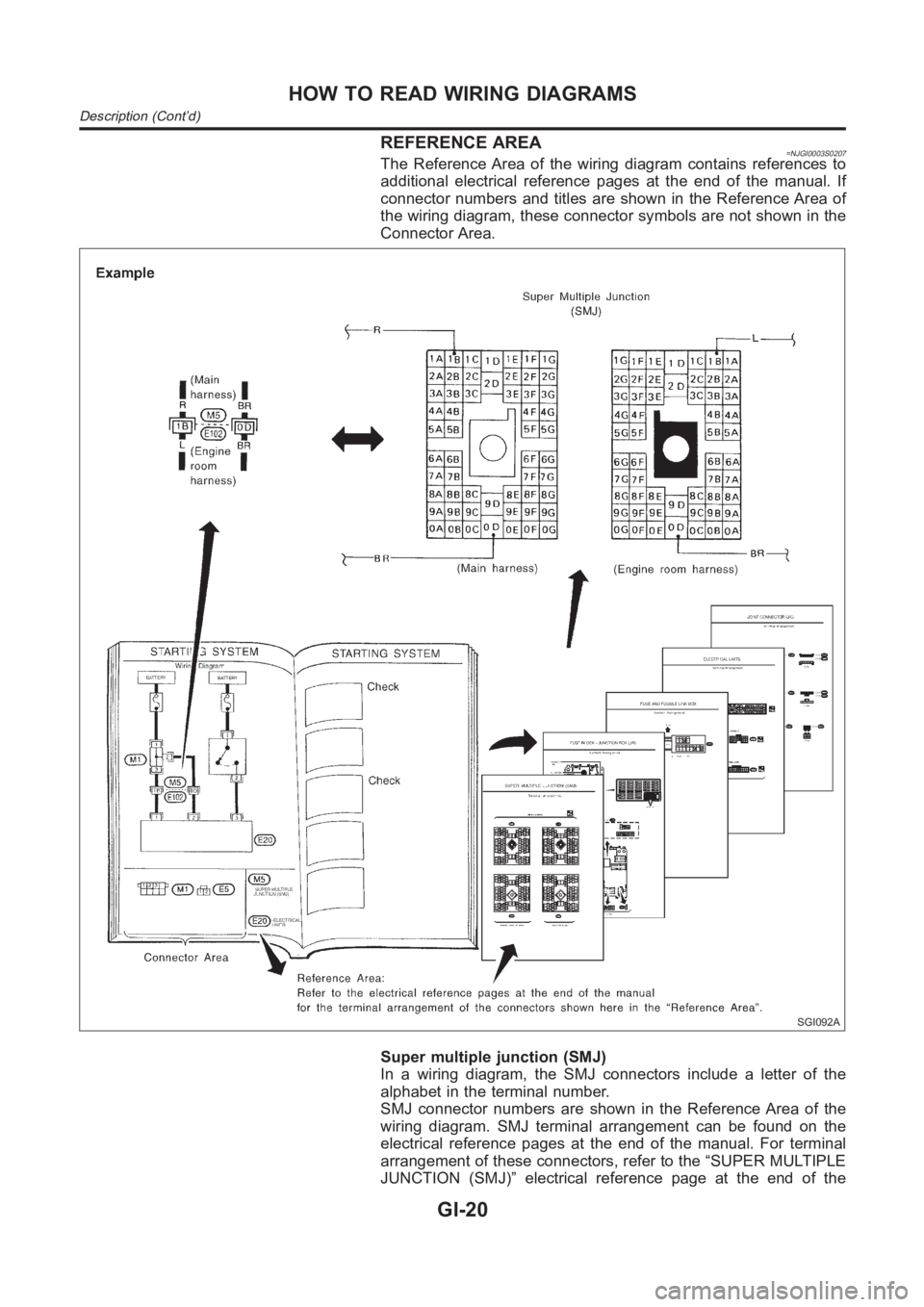
REFERENCE AREA=NJGI0003S0207The Reference Area of the wiring diagram contains references to
additional electrical reference pages at the end of the manual. If
connector numbers and titles are shown in the Reference Area of
the wiring diagram, these connector symbols are not shown in the
Connector Area.
SGI092A
Super multiple junction (SMJ)
In a wiring diagram, the SMJ connectors include a letter of the
alphabet in the terminal number.
SMJ connector numbers are shown in the Reference Area of the
wiring diagram. SMJ terminal arrangement can be found on the
electrical reference pages at the end of the manual. For terminal
arrangement of these connectors, refer to the “SUPER MULTIPLE
JUNCTION (SMJ)” electrical reference page at the end of the
HOW TO READ WIRING DIAGRAMS
Description (Cont’d)
GI-20
Page 56 of 3189
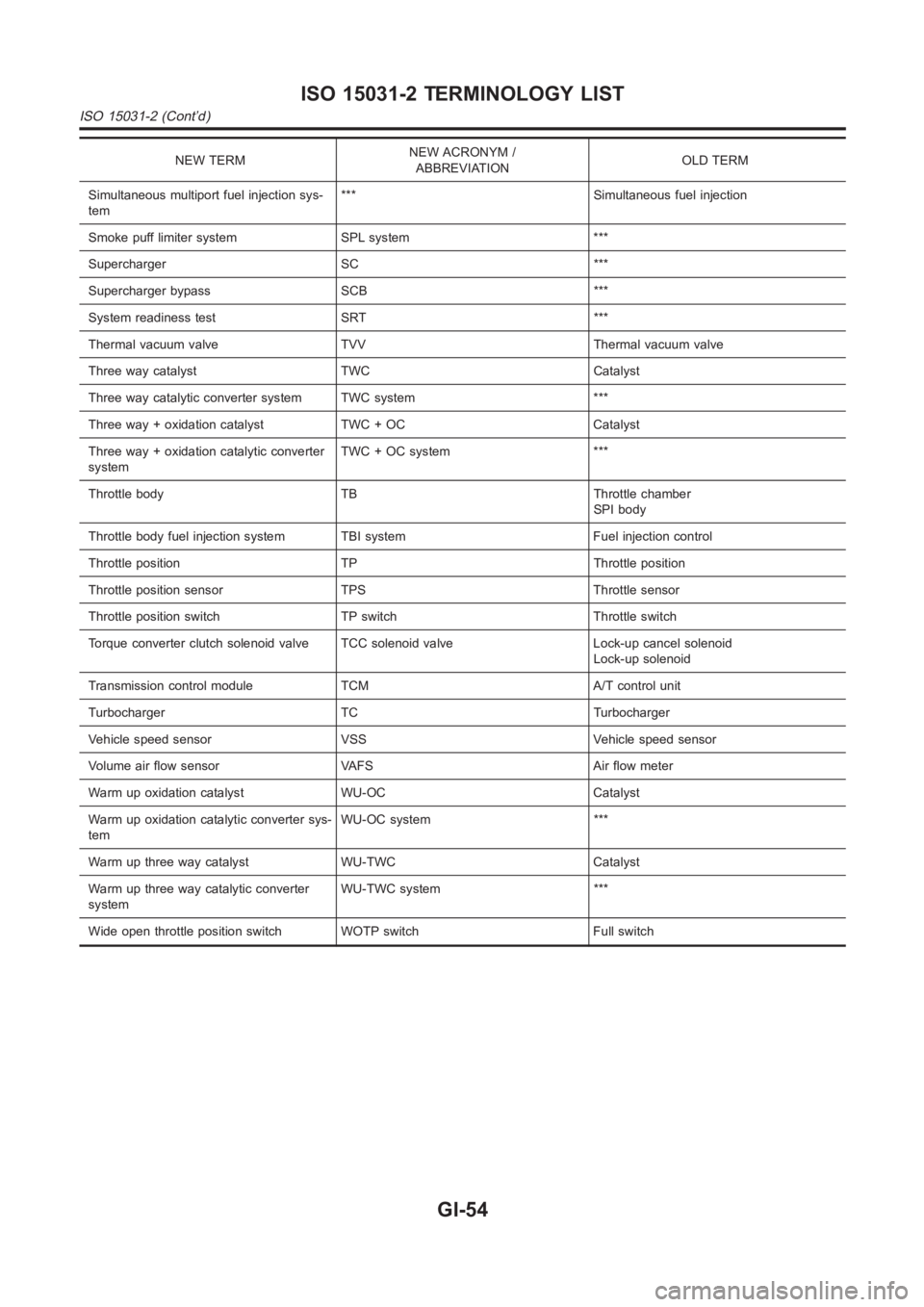
NEW TERMNEW ACRONYM /
ABBREVIATIONOLD TERM
Simultaneous multiport fuel injection sys-
tem*** Simultaneous fuel injection
Smoke puff limiter system SPL system ***
Supercharger SC ***
Supercharger bypass SCB ***
System readiness test SRT ***
Thermal vacuum valve TVV Thermal vacuum valve
Three way catalyst TWC Catalyst
Three way catalytic converter system TWC system ***
Three way + oxidation catalyst TWC + OC Catalyst
Three way + oxidation catalytic converter
systemTWC + OC system ***
Throttle body TB Throttle chamber
SPI body
Throttle body fuel injection system TBI system Fuel injection control
Throttle position TP Throttle position
Throttle position sensor TPS Throttle sensor
Throttle position switch TP switch Throttle switch
Torque converter clutch solenoid valve TCC solenoid valve Lock-up cancelsolenoid
Lock-up solenoid
Transmission control module TCM A/T control unit
Turbocharger TC Turbocharger
Vehicle speed sensor VSS Vehicle speed sensor
Volume air flow sensor VAFS Air flow meter
Warm up oxidation catalyst WU-OC Catalyst
Warm up oxidation catalytic converter sys-
temWU-OC system ***
Warm up three way catalyst WU-TWC Catalyst
Warm up three way catalytic converter
systemWU-TWC system ***
Wide open throttle position switch WOTP switch Full switch
ISO 15031-2 TERMINOLOGY LIST
ISO 15031-2 (Cont’d)
GI-54
Page 2339 of 3189
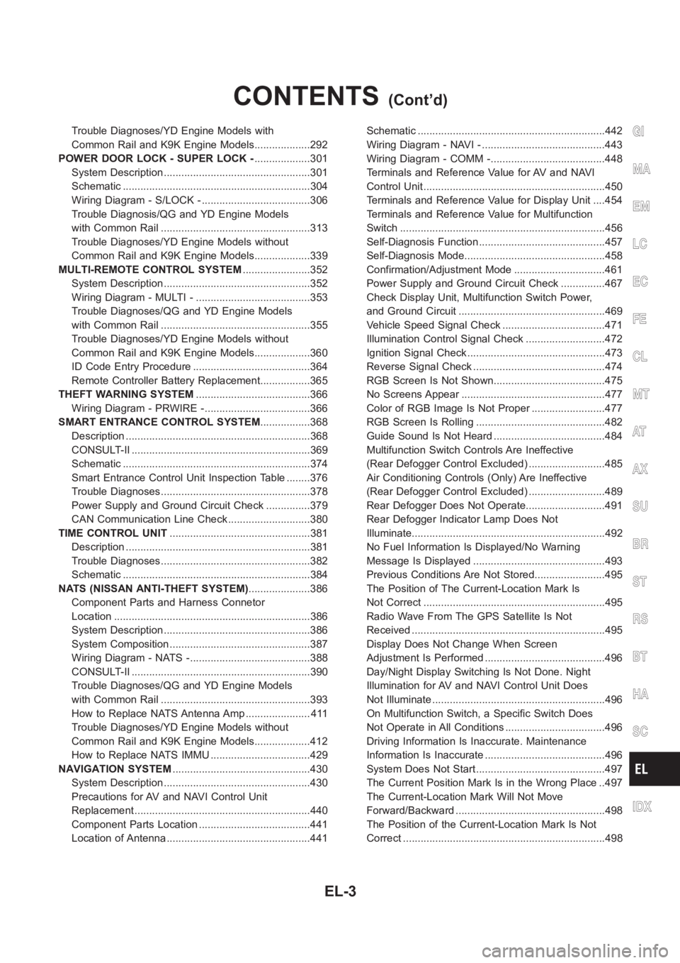
Trouble Diagnoses/YD Engine Models with
Common Rail and K9K Engine Models...................292
POWER DOOR LOCK - SUPER LOCK -...................301
System Description ..................................................301
Schematic <0011001100110011001100110011001100110011001100110011001100110011001100110011001100110011001100110011001100110011001100110011001100110011001100110011001100110011001100110011001100110011001100110011001100
11001100110011[..........304
Wiring Diagram - S/LOCK - .....................................306
Trouble Diagnosis/QG and YD Engine Models
with Common Rail ...................................................313
Trouble Diagnoses/YD Engine Models without
Common Rail and K9K Engine Models...................339
MULTI-REMOTE CONTROL SYSTEM.......................352
System Description ..................................................352
Wiring Diagram - MULTI - .......................................353
Trouble Diagnoses/QG and YD Engine Models
with Common Rail ...................................................355
Trouble Diagnoses/YD Engine Models without
Common Rail and K9K Engine Models...................360
ID Code Entry Procedure ........................................364
Remote Controller Battery Replacement.................365
THEFT WARNING SYSTEM.......................................366
Wiring Diagram - PRWIRE -....................................366
SMART ENTRANCE CONTROL SYSTEM.................368
Description <0011001100110011001100110011001100110011001100110011001100110011001100110011001100110011001100110011001100110011001100110011001100110011001100110011001100110011001100110011001100110011001100110011001100
110011[...........368
CONSULT-II <0011001100110011001100110011001100110011001100110011001100110011001100110011001100110011001100110011001100110011001100110011001100110011001100110011001100110011001100110011001100110011001100110011001100
1100110011[........369
Schematic <0011001100110011001100110011001100110011001100110011001100110011001100110011001100110011001100110011001100110011001100110011001100110011001100110011001100110011001100110011001100110011001100110011001100
11001100110011[..........374
Smart Entrance Control Unit Inspection Table ........376
Trouble Diagnoses...................................................378
Power Supply and Ground Circuit Check ...............379
CAN Communication Line Check ............................380
TIME CONTROL UNIT................................................381
Description <0011001100110011001100110011001100110011001100110011001100110011001100110011001100110011001100110011001100110011001100110011001100110011001100110011001100110011001100110011001100110011001100110011001100
110011[...........381
Trouble Diagnoses...................................................382
Schematic <0011001100110011001100110011001100110011001100110011001100110011001100110011001100110011001100110011001100110011001100110011001100110011001100110011001100110011001100110011001100110011001100110011001100
11001100110011[..........384
NATS (NISSAN ANTI-THEFT SYSTEM).....................386
Component Parts and Harness Connetor
Location <0011001100110011001100110011001100110011001100110011001100110011001100110011001100110011001100110011001100110011001100110011001100110011001100110011001100110011001100110011001100110011001100110011001100
110011001100110011[............386
System Description ..................................................386
System Composition ................................................387
Wiring Diagram - NATS -.........................................388
CONSULT-II <0011001100110011001100110011001100110011001100110011001100110011001100110011001100110011001100110011001100110011001100110011001100110011001100110011001100110011001100110011001100110011001100110011001100
1100110011[........390
Trouble Diagnoses/QG and YD Engine Models
with Common Rail ...................................................393
How to Replace NATS Antenna Amp ...................... 411
Trouble Diagnoses/YD Engine Models without
Common Rail and K9K Engine Models...................412
How to Replace NATS IMMU ..................................429
NAVIGATION SYSTEM...............................................430
System Description ..................................................430
Precautions for AV and NAVI Control Unit
Replacement <0011001100110011001100110011001100110011001100110011001100110011001100110011001100110011001100110011001100110011001100110011001100110011001100110011001100110011001100110011001100110011001100110011001100
110011[........440
Component Parts Location ......................................441
Location of Antenna .................................................441Schematic <0011001100110011001100110011001100110011001100110011001100110011001100110011001100110011001100110011001100110011001100110011001100110011001100110011001100110011001100110011001100110011001100110011001100
11001100110011[..........442
Wiring Diagram - NAVI - ..........................................443
Wiring Diagram - COMM -.......................................448
Terminals and Reference Value for AV and NAVI
Control Unit <0011001100110011001100110011001100110011001100110011001100110011001100110011001100110011001100110011001100110011001100110011001100110011001100110011001100110011001100110011001100110011001100110011001100
110011[..........450
Terminals and Reference Value for Display Unit ....454
Terminals and Reference Value for Multifunction
Switch <0011001100110011001100110011001100110011001100110011001100110011001100110011001100110011001100110011001100110011001100110011001100110011001100110011001100110011001100110011001100110011001100110011001100
11001100110011001100110011[.............456
Self-Diagnosis Function ...........................................457
Self-Diagnosis Mode................................................458
Confirmation/Adjustment Mode ...............................461
Power Supply and Ground Circuit Check ...............467
Check Display Unit, Multifunction Switch Power,
and Ground Circuit ..................................................469
Vehicle Speed Signal Check ...................................471
Illumination Control Signal Check ...........................472
Ignition Signal Check ...............................................473
Reverse Signal Check .............................................474
RGB Screen Is Not Shown......................................475
No Screens Appear .................................................477
Color of RGB Image Is Not Proper .........................477
RGB Screen Is Rolling ............................................482
Guide Sound Is Not Heard ......................................484
Multifunction Switch Controls Are Ineffective
(Rear Defogger Control Excluded) ..........................485
Air Conditioning Controls (Only) Are Ineffective
(Rear Defogger Control Excluded) ..........................489
Rear Defogger Does Not Operate...........................491
Rear Defogger Indicator Lamp Does Not
Illuminate<0011001100110011001100110011001100110011001100110011001100110011001100110011001100110011001100110011001100110011001100110011001100110011001100110011001100110011001100110011001100110011001100110011001100
1100110011[.............492
No Fuel Information Is Displayed/No Warning
Message Is Displayed .............................................493
Previous Conditions Are Not Stored........................495
The Position of The Current-Location Mark Is
Not Correct <0011001100110011001100110011001100110011001100110011001100110011001100110011001100110011001100110011001100110011001100110011001100110011001100110011001100110011001100110011001100110011001100110011001100
1100110011[.........495
Radio Wave From The GPS Satellite Is Not
Received <0011001100110011001100110011001100110011001100110011001100110011001100110011001100110011001100110011001100110011001100110011001100110011001100110011001100110011001100110011001100110011001100110011001100
110011001100110011[...........495
Display Does Not Change When Screen
Adjustment Is Performed .........................................496
Day/Night Display Switching Is Not Done. Night
Illumination for AV and NAVI Control Unit Does
Not Illuminate ...........................................................496
On Multifunction Switch, a Specific Switch Does
Not Operate in All Conditions ..................................496
Driving Information Is Inaccurate. Maintenance
Information Is Inaccurate .........................................496
System Does Not Start ............................................497
The Current Position Mark Is in the Wrong Place ..497
The Current-Location Mark Will Not Move
Forward/Backward ...................................................498
The Position of the Current-Location Mark Is Not
Correct <0011001100110011001100110011001100110011001100110011001100110011001100110011001100110011001100110011001100110011001100110011001100110011001100110011001100110011001100110011001100110011001100110011001100
1100110011001100110011[.............498
GI
MA
EM
LC
EC
FE
CL
MT
AT
AX
SU
BR
ST
RS
BT
HA
SC
IDX
CONTENTS(Cont’d)
EL-3
Page 2637 of 3189
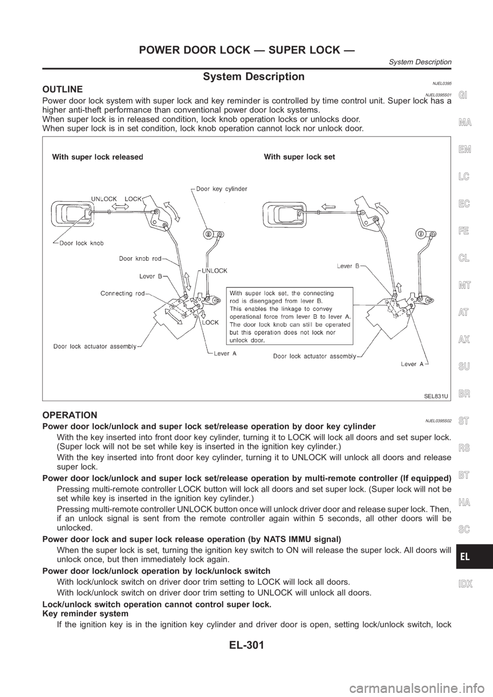
System DescriptionNJEL0395OUTLINENJEL0395S01Power door lock system with super lock and key reminder is controlled by time control unit. Super lock has a
higher anti-theft performance than conventional power door lock systems.
When super lock is in released condition, lock knob operation locks or unlocks door.
When super lock is in set condition, lock knob operation cannot lock nor unlock door.
SEL831U
OPERATIONNJEL0395S02Power door lock/unlock and super lock set/release operation by door key cylinder
With the key inserted into front door key cylinder, turning it to LOCK will lock all doors and set super lock.
(Super lock will not be set while key is inserted in the ignition key cylinder. )
With the key inserted into front door key cylinder, turning it to UNLOCK will unlock all doors and release
super lock.
Power door lock/unlock and super lock set/release operation by multi-remote controller (If equipped)
Pressing multi-remote controller LOCK button will lock all doors and set super lock. (Super lock will not be
set while key is inserted in the ignition key cylinder.)
Pressing multi-remote controller UNLOCK button once will unlock driver door and release super lock. Then,
if an unlock signal is sent from the remote controller again within 5 seconds, all other doors will be
unlocked.
Power door lock and super lock release operation (by NATS IMMU signal)
When the super lock is set, turning the ignition key switch to ON will release the super lock. All doors will
unlock once, but then immediately lock again.
Power door lock/unlock operation by lock/unlock switch
With lock/unlock switch on driver door trim setting to LOCK will lock all doors.
With lock/unlock switch on driver door trim setting to UNLOCK will unlock all doors.
Lock/unlock switch operation cannot control super lock.
Key reminder system
If the ignition key is in the ignition key cylinder and driver door is open, setting lock/unlock switch, lock
GI
MA
EM
LC
EC
FE
CL
MT
AT
AX
SU
BR
ST
RS
BT
HA
SC
IDX
POWER DOOR LOCK — SUPER LOCK —
System Description
EL-301
Page 2638 of 3189
knob, key or multi-remote controller to “LOCK” locks the door once but thenimmediately unlocks all doors.
(signal from door unlock sensor driver side)
System initialization
System initialization is required when battery cables are reconnected. Conduct the following to release
super lock once;
— insert the key into the ignition key cylinder and turn it to ON.
— LOCK/UNLOCK operation using door key cylinder or multi-remote controller.
POWER DOOR LOCK — SUPER LOCK —
System Description (Cont’d)
EL-302
Page 2639 of 3189
NOTE:
GI
MA
EM
LC
EC
FE
CL
MT
AT
AX
SU
BR
ST
RS
BT
HA
SC
IDX
POWER DOOR LOCK — SUPER LOCK —
System Description (Cont’d)
EL-303
Page 2640 of 3189
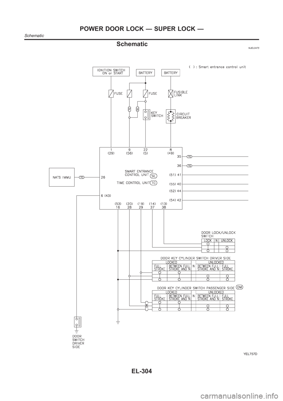
SchematicNJEL0475
YEL757D
POWER DOOR LOCK — SUPER LOCK —
Schematic
EL-304