2003 NISSAN ALMERA N16 Super
[x] Cancel search: SuperPage 2704 of 3189
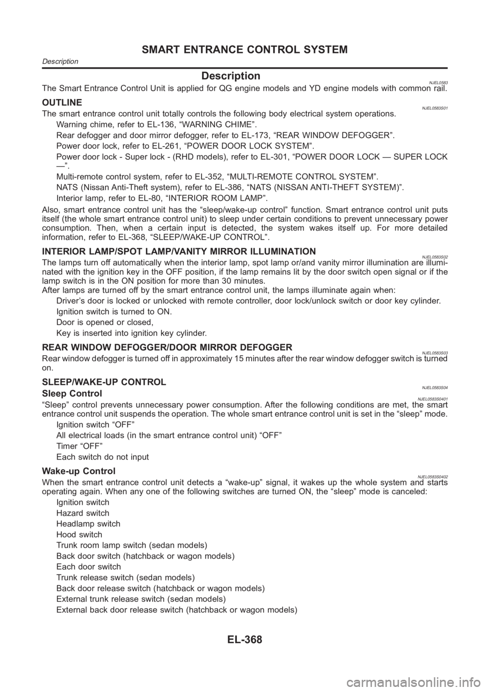
DescriptionNJEL0583The Smart Entrance Control Unit is applied for QG engine models and YD engine models with common rail.
OUTLINENJEL0583S01The smart entrance control unit totally controls the following body electrical system operations.
Warning chime, refer to EL-136, “WARNING CHIME”.
Rear defogger and door mirror defogger, refer to EL-173, “REAR WINDOW DEFOGGER”.
Power door lock, refer to EL-261, “POWER DOOR LOCK SYSTEM”.
Power door lock - Super lock - (RHD models), refer to EL-301, “POWER DOOR LOCK — SUPER LOCK
—”.
Multi-remote control system, refer to EL-352, “MULTI-REMOTE CONTROL SYSTEM”.
NATS (Nissan Anti-Theft system), refer to EL-386, “NATS (NISSAN ANTI-THEFT SYSTEM)”.
Interior lamp, refer to EL-80, “INTERIOR ROOM LAMP”.
Also, smart entrance control unit has the “sleep/wake-up control” function. Smart entrance control unit puts
itself (the whole smart entrance control unit) to sleep under certain conditions to prevent unnecessary power
consumption. Then, when a certain input is detected, the system wakes itself up. For more detailed
information, refer to EL-368, “SLEEP/WAKE-UP CONTROL”.
INTERIOR LAMP/SPOT LAMP/VANITY MIRROR ILLUMINATIONNJEL0583S02The lamps turn off automatically when the interior lamp, spot lamp or/and vanity mirror illumination are illumi-
nated with the ignition key in the OFF position, if the lamp remains lit by the door switch open signal or if the
lamp switch is in the ON position for more than 30 minutes.
After lamps are turned off by the smart entrance control unit, the lamps illuminate again when:
Driver’s door is locked or unlocked with remote controller, door lock/unlock switch or door key cylinder.
Ignition switch is turned to ON.
Door is opened or closed,
Key is inserted into ignition key cylinder.
REAR WINDOW DEFOGGER/DOOR MIRROR DEFOGGERNJEL0583S03Rear window defogger is turned off in approximately 15 minutes after the rear window defogger switch is turned
on.
SLEEP/WAKE-UP CONTROLNJEL0583S04Sleep ControlNJEL0583S0401“Sleep” control prevents unnecessary power consumption. After the following conditions are met, the smart
entrance control unit suspends the operation. The whole smart entrance control unit is set in the “sleep” mode.
Ignition switch “OFF”
All electrical loads (in the smart entrance control unit) “OFF”
Timer “OFF”
Each switch do not input
Wake-up ControlNJEL0583S0402When the smart entrance control unit detects a “wake-up” signal, it wakes up the whole system and starts
operating again. When any one of the following switches are turned ON, the “sleep” mode is canceled:
Ignition switch
Hazard switch
Headlamp switch
Hood switch
Trunk room lamp switch (sedan models)
Back door switch (hatchback or wagon models)
Each door switch
Trunk release switch (sedan models)
Back door release switch (hatchback or wagon models)
External trunk release switch (sedan models)
External back door release switch (hatchback or wagon models)
SMART ENTRANCE CONTROL SYSTEM
Description
EL-368
Page 2713 of 3189
![NISSAN ALMERA N16 2003 Electronic Repair Manual Terminal
No.Wire
colorConnections Operated condition Voltage (Approximate values)
24 BRWasher switch
(Headlamp washer switch)[Head lamp switch 1st or 2nd posi-
tion]
Washer switch OFF,ON12V,0V
25 G/OR NISSAN ALMERA N16 2003 Electronic Repair Manual Terminal
No.Wire
colorConnections Operated condition Voltage (Approximate values)
24 BRWasher switch
(Headlamp washer switch)[Head lamp switch 1st or 2nd posi-
tion]
Washer switch OFF,ON12V,0V
25 G/OR](/manual-img/5/57350/w960_57350-2712.png)
Terminal
No.Wire
colorConnections Operated condition Voltage (Approximate values)
24 BRWasher switch
(Headlamp washer switch)[Head lamp switch 1st or 2nd posi-
tion]
Washer switch OFF,ON12V,0V
25 G/ORCombination switch
(Turn signal switch)Turn signal switch:
Neutral,Left turn position12V,0V
26 L/BCombination switch
(Turn signal switch)Turn signal switch:
Neutral,Right turn position12V,0V
27 Y/BVehicle security horn relay
(RHD models)When theft warning system:
Armed,Disarmed0V,12V
28 R/Y Interior room lampWhen interior lamp is operated using
remote controller (Lamp switch in
“DOOR” position)12V,0V
29 Y/G Ignition key switch Ignition key is in “ON” position 12V
30 G/R Hazard switch Hazard switch: OFF,ON 12V,0V
31 W Rear window defogger relay[Ignition switch “ON”]
Rear window defogger switch:
OFF,ON12V,0V
32 LG/B Cooling fan relay[Ignition switch“ ON”]
Cooling fan: Operating,Not operat-
ing0V,12V
33 LG/R Cooling fan relay[Ignition switch “ON”]
Cooling fan: Operating,Not operat-
ing0V,12V
34 L/Y Security indicator Ignition switch ON,OFF 12V,0V
39 BR/WRear door switch
(Passenger side)Rear door LH or RH: Open,Closed 0V,12V
41 L Air conditioner relay[Engine is running]
Air conditioner switch: ON,
OFF12V,0V
43 R/WFront door switch
(Driver side)Front door (Driver side):
Open,Closed12V,0V
44 R/WFront door switch
(Passenger side)Front door (Passenger side):
Open,Closed0V,12V
45 R/YRear door switch
(Driver side)Rear door LH or RH: Open,Closed 0V,12V
49 W/L Power source — 12V
50 GPower door super lock actuator
(Rear)Remote controller door lock switch:
Free,Press0V,12V
51 L/R Driver door lock actuatorDoor lock & unlock switch:
Free,Lock0V,12V
52 W/R Door lock actuatorsDoor lock & unlock switch:
Free,Unlock0V,12V
53 B Ground — 0V
54 R/B Door lock actuatorsDoor lock & unlock switch:
Free,Unlock0V,12V
55 W/BPower door super lock actuator
(Front)Remote controller door lock switch:
Free,Unlock0V,12V
56 R/B Power source — 12V
GI
MA
EM
LC
EC
FE
CL
MT
AT
AX
SU
BR
ST
RS
BT
HA
SC
IDX
SMART ENTRANCE CONTROL SYSTEM
Smart Entrance Control Unit Inspection Table (Cont’d)
EL-377
Page 2717 of 3189
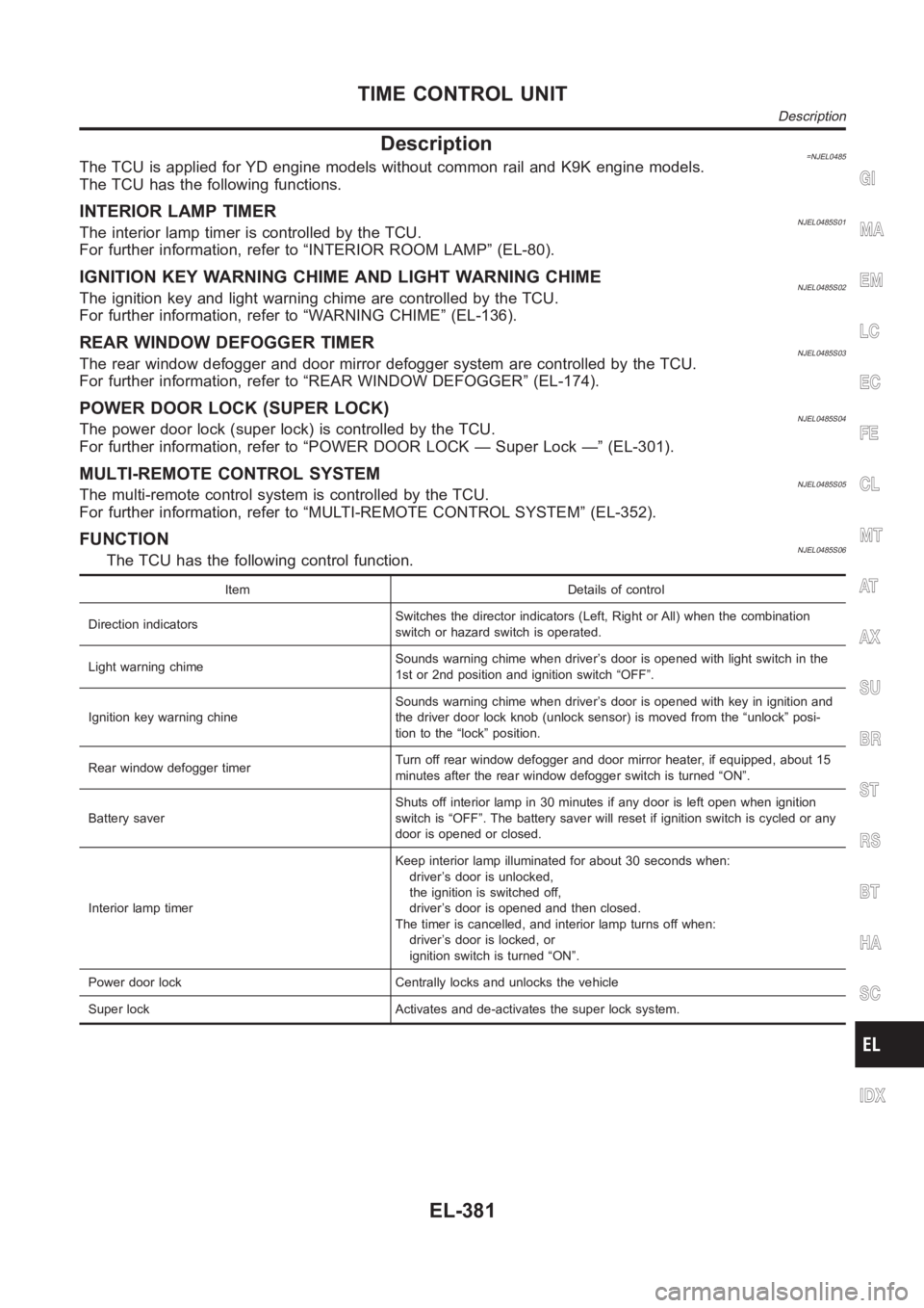
Description=NJEL0485The TCU is applied for YD engine models without common rail and K9K engine models.
The TCU has the following functions.
INTERIOR LAMP TIMERNJEL0485S01The interior lamp timer is controlled by the TCU.
For further information, refer to “INTERIOR ROOM LAMP” (EL-80).
IGNITION KEY WARNING CHIME AND LIGHT WARNING CHIMENJEL0485S02The ignition key and light warning chime are controlled by the TCU.
For further information, refer to “WARNING CHIME” (EL-136).
REAR WINDOW DEFOGGER TIMERNJEL0485S03The rear window defogger and door mirror defogger system are controlled bythe TCU.
For further information, refer to “REAR WINDOW DEFOGGER” (EL-174).
POWER DOOR LOCK (SUPER LOCK)NJEL0485S04The power door lock (super lock) is controlled by the TCU.
For further information, refer to “POWER DOOR LOCK — Super Lock —” (EL-301).
MULTI-REMOTE CONTROL SYSTEMNJEL0485S05The multi-remote control system is controlled by the TCU.
For further information, refer to “MULTI-REMOTE CONTROL SYSTEM” (EL-352).
FUNCTIONNJEL0485S06The TCU has the following control function.
Item Details of control
Direction indicatorsSwitches the director indicators (Left, Right or All) when the combination
switch or hazard switch is operated.
Light warning chimeSounds warning chime when driver’s door is opened with light switch in the
1st or 2nd position and ignition switch “OFF”.
Ignition key warning chineSounds warning chime when driver’s door is opened with key in ignition and
the driver door lock knob (unlock sensor) is moved from the “unlock” posi-
tion to the “lock” position.
Rear window defogger timerTurn off rear window defogger and door mirror heater, if equipped, about 15
minutes after the rear window defogger switch is turned “ON”.
Battery saverShuts off interior lamp in 30 minutes if any door is left open when ignition
switch is “OFF”. The battery saver will reset if ignition switch is cycled or any
door is opened or closed.
Interior lamp timerKeep interior lamp illuminated for about 30 seconds when:
driver’s door is unlocked,
the ignition is switched off,
driver’s door is opened and then closed.
The timer is cancelled, and interior lamp turns off when:
driver’s door is locked, or
ignition switch is turned “ON”.
Power door lock Centrally locks and unlocks the vehicle
Super lock Activates and de-activates the super lock system.
GI
MA
EM
LC
EC
FE
CL
MT
AT
AX
SU
BR
ST
RS
BT
HA
SC
IDX
TIME CONTROL UNIT
Description
EL-381
Page 2786 of 3189
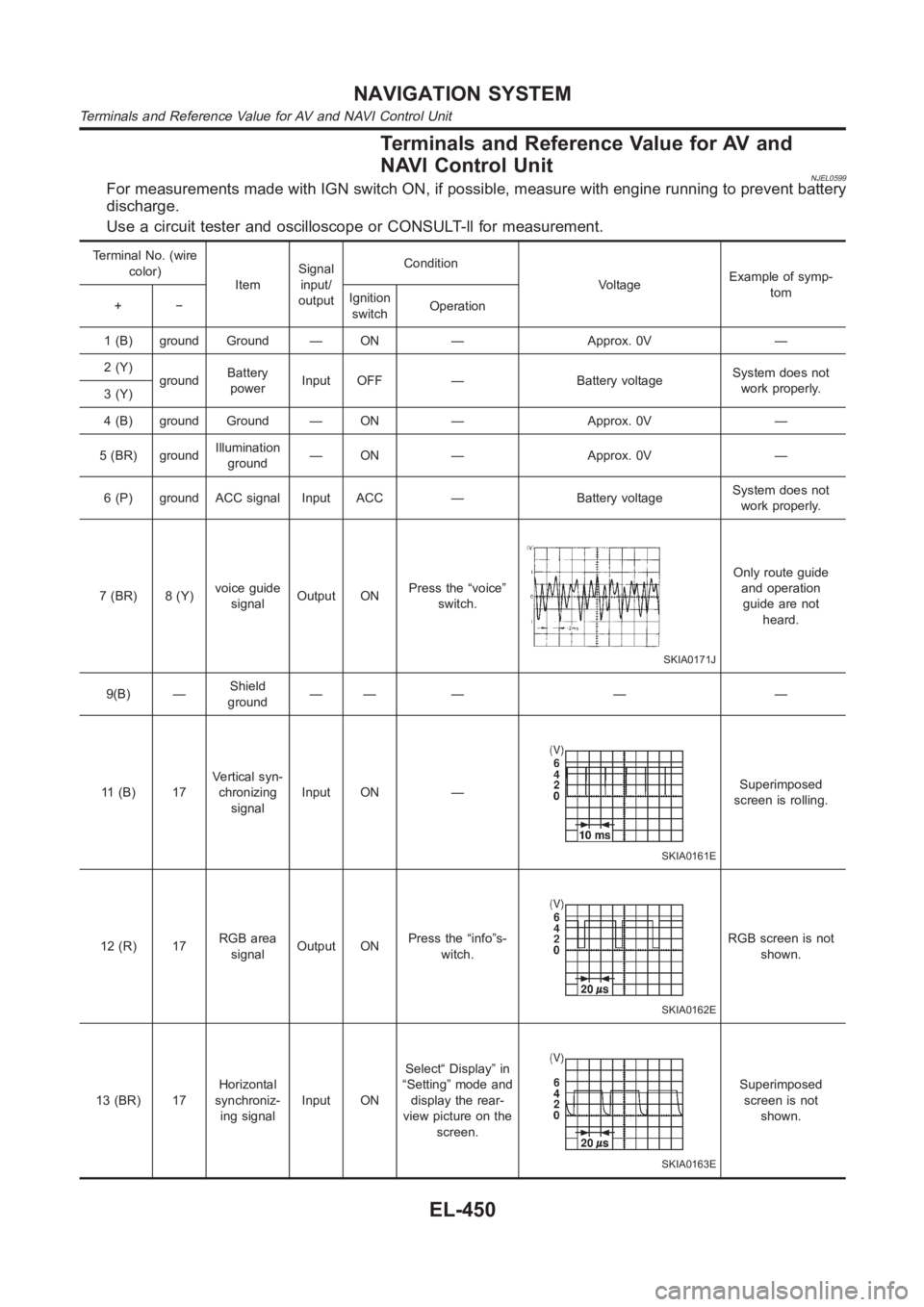
Terminals and Reference Value for AV and
NAVI Control Unit
NJEL0599For measurements made with IGN switch ON, if possible, measure with enginerunning to prevent battery
discharge.
Use a circuit tester and oscilloscope or CONSULT-ll for measurement.
Terminal No. (wire
color)
ItemSignal
input/
outputCondition
VoltageExample of symp-
tom
+−Ignition
switchOperation
1 (B) ground Ground — ON — Approx. 0V —
2 (Y)
groundBattery
powerInput OFF — Battery voltageSystem does not
work properly.
3 (Y)
4 (B) ground Ground — ON — Approx. 0V —
5 (BR) groundIllumination
ground— ON — Approx. 0V —
6 (P) ground ACC signal Input ACC — Battery voltageSystem does not
work properly.
7 (BR) 8 (Y)voice guide
signalOutput ONPress the “voice”
switch.
SKIA0171J
Only route guide
and operation
guide are not
heard.
9(B) —Shield
ground—— — — —
11 (B) 17Vertical syn-
chronizing
signalInput ON —
SKIA0161E
Superimposed
screen is rolling.
12 (R) 17RGB area
signalOutput ONPress the “info”s-
witch.
SKIA0162E
RGB screen is not
shown.
13 (BR) 17Horizontal
synchroniz-
ing signalInput ONSelect“ Display” in
“Setting” mode and
display the rear-
view picture on the
screen.
SKIA0163E
Superimposed
screen is not
shown.
NAVIGATION SYSTEM
Terminals and Reference Value for AV and NAVI Control Unit
EL-450
Page 2790 of 3189
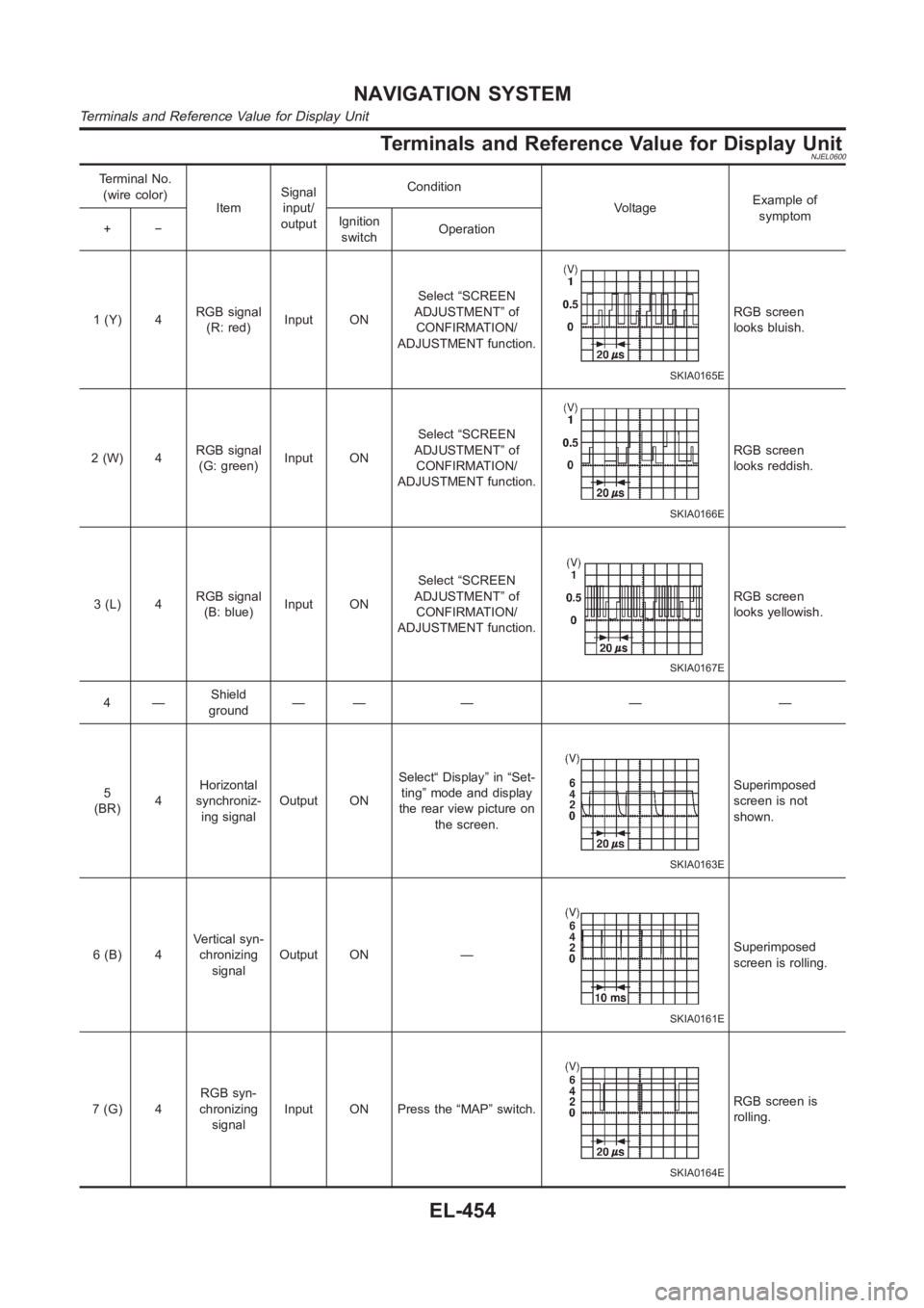
Terminals and Reference Value for Display UnitNJEL0600
Terminal No.
(wire color)
ItemSignal
input/
outputCondition
VoltageExample of
symptom
+−Ignition
switchOperation
1 (Y) 4RGB signal
(R: red)Input ONSelect “SCREEN
ADJUSTMENT” of
CONFIRMATION/
ADJUSTMENT function.
SKIA0165E
RGB screen
looks bluish.
2(W) 4RGB signal
(G: green)Input ONSelect “SCREEN
ADJUSTMENT” of
CONFIRMATION/
ADJUSTMENT function.
SKIA0166E
RGB screen
looks reddish.
3(L) 4RGB signal
(B: blue)Input ONSelect “SCREEN
ADJUSTMENT” of
CONFIRMATION/
ADJUSTMENT function.
SKIA0167E
RGB screen
looks yellowish.
4—Shield
ground—— — — —
5
(BR)4Horizontal
synchroniz-
ing signalOutput ONSelect“ Display” in “Set-
ting” mode and display
the rear view picture on
the screen.
SKIA0163E
Superimposed
screen is not
shown.
6 (B) 4Vertical syn-
chronizing
signalOutput ON —
SKIA0161E
Superimposed
screen is rolling.
7(G) 4RGB syn-
chronizing
signalInput ON Press the “MAP” switch.
SKIA0164E
RGB screen is
rolling.
NAVIGATION SYSTEM
Terminals and Reference Value for Display Unit
EL-454
Page 2936 of 3189
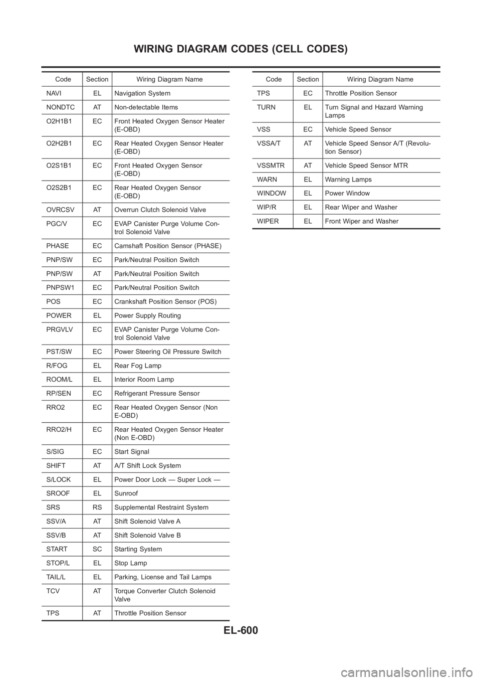
Code Section Wiring Diagram Name
NAVI EL Navigation System
NONDTC AT Non-detectable Items
O2H1B1 EC Front Heated Oxygen Sensor Heater
(E-OBD)
O2H2B1 EC Rear Heated Oxygen Sensor Heater
(E-OBD)
O2S1B1 EC Front Heated Oxygen Sensor
(E-OBD)
O2S2B1 EC Rear Heated Oxygen Sensor
(E-OBD)
OVRCSV AT Overrun Clutch Solenoid Valve
PGC/V EC EVAP Canister Purge Volume Con-
trol Solenoid Valve
PHASE EC Camshaft Position Sensor (PHASE)
PNP/SW EC Park/Neutral Position Switch
PNP/SW AT Park/Neutral Position Switch
PNPSW1 EC Park/Neutral Position Switch
POS EC Crankshaft Position Sensor (POS)
POWER EL Power Supply Routing
PRGVLV EC EVAP Canister Purge Volume Con-
trol Solenoid Valve
PST/SW EC Power Steering Oil Pressure Switch
R/FOG EL Rear Fog Lamp
ROOM/L EL Interior Room Lamp
RP/SEN EC Refrigerant Pressure Sensor
RRO2 EC Rear Heated Oxygen Sensor (Non
E-OBD)
RRO2/H EC Rear Heated Oxygen Sensor Heater
(Non E-OBD)
S/SIG EC Start Signal
SHIFT AT A/T Shift Lock System
S/LOCK EL Power Door Lock — Super Lock —
SROOF EL Sunroof
SRS RS Supplemental Restraint System
SSV/A AT Shift Solenoid Valve A
SSV/B AT Shift Solenoid Valve B
START SC Starting System
STOP/L EL Stop Lamp
TAIL/L EL Parking, License and Tail Lamps
TCV AT Torque Converter Clutch Solenoid
Valve
TPS AT Throttle Position SensorCode Section Wiring Diagram Name
TPS EC Throttle Position Sensor
TURN EL Turn Signal and Hazard Warning
Lamps
VSS EC Vehicle Speed Sensor
VSSA/T AT Vehicle Speed Sensor A/T (Revolu-
tion Sensor)
VSSMTR AT Vehicle Speed Sensor MTR
WARN EL Warning Lamps
WINDOW EL Power Window
WIP/R EL Rear Wiper and Washer
WIPER EL Front Wiper and Washer
WIRING DIAGRAM CODES (CELL CODES)
EL-600
Page 3183 of 3189
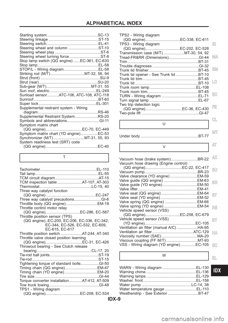
Starting system...............................................SC-13
Steering linkage ..............................................ST-15
Steering switch................................................EL-41
Steering wheel and column ............................ST-10
Steering wheel play ..........................................ST-6
Steering wheel turning force .............................ST-8
Stop lamp switch (QG engine) ......EC-361, EC-630
Stop lamp <0011001100110011001100110011001100110011001100110011001100110011001100110011001100110011001100110011001100110011001100110011001100110011001100110011001100110011001100110011001100110011001100110011001100
110011001100110011[.EL-58
STOP/L - Wiring diagram................................EL-58
Striking rod (M/T) ...............................MT-32, 56, 94
Strut (front) <0011001100110011001100110011001100110011001100110011001100110011001100110011001100110011001100110011001100110011001100110011001100110011001100110011001100110011001100110011001100110011001100110011001100
11[....SU-9
Strut (rear) <0011001100110011001100110011001100110011001100110011001100110011001100110011001100110011001100110011001100110011001100110011001100110011001100110011001100110011001100110011001100110011001100110011001100
110011[..SU-20
Sub-gear (M/T) .........................................MT-31, 55
Sun roof, electric ...........................................EL-249
Sunload sensor...........ATC-106, ATC-108, ATC-118
Sunroof<0011001100110011001100110011001100110011001100110011001100110011001100110011001100110011001100110011001100110011001100110011001100110011001100110011001100110011001100110011001100110011001100110011001100
1100110011001100110011[....BT-60
Super lock <0011001100110011001100110011001100110011001100110011001100110011001100110011001100110011001100110011001100110011001100110011001100110011001100110011001100110011001100110011001100110011001100110011001100
11001100110028[L-301
Supplemental restraint system - Wiring
diagram <0011001100110011001100110011001100110011001100110011001100110011001100110011001100110011001100110011001100110011001100110011001100110011001100110011001100110011001100110011001100110011001100110011001100
1100110011001100110035[S-46
Supplemental Restraint System .....................RS-20
Symbols and abbreviations..............................GI-11
Symptom matrix chart
(QG engine)..................................EC-70, EC-449
Symptom matrix chart (YD engine)................EC-53
Synchronizer (M/T) ............................MT-31, 55, 93
System readiness test (SRT) code
(QG engine) ................................................EC-40
T
Tachometer <0011001100110011001100110011001100110011001100110011001100110011001100110011001100110011001100110011001100110011001100110011001100110011001100110011001100110011001100110011001100110011001100110011001100
1100110028[L-110
Tail lamp <0011001100110011001100110011001100110011001100110011001100110011001100110011001100110011001100110011001100110011001100110011001100110011001100110011001100110011001100110011001100110011001100110011001100
110011001100110011[...EL-55
TCM circuit diagram ........................................AT-15
TCM inspection table .......................AT-107, AT-303
Thermostat................................................LC-15,40
Three way catalyst function
(QG engine) ..............................................EC-247
Three way catalyst precautions.........................GI-6
Throttle body (QG engine) .............................EM-18
Throttle control motor relay
(QG engine)................................EC-286, EC-587
Throttle position sensor (TPS)
(QG engine) ..EC-200, EC-206, EC-336, EC-342,
EC-344, EC-526, EC-532, EC-609,
EC-615, EC-617
Throttle position switch ....................AT-244, AT-340
Throttle valve closed position learning
(QG engine)..................................EC-31, EC-426
Throwout bearing - See Clutch release
bearing ..................................................CL-17,20
Tie-rod ball joints.............................................ST- 1 9
Tie-rod <0011001100110011001100110011001100110011001100110011001100110011001100110011001100110011001100110011001100110011001100110011001100110011001100110011001100110011001100110011001100110011001100110011001100
1100110011001100110011[.....ST-15
Tightening torque of standard bolts.................GI-50
Timing chain (QG engine)..............................EM-47
Timing chain (YD engine) ..............................EM-20
Tire size <0011001100110011001100110011001100110011001100110011001100110011001100110011001100110011001100110011001100110011001100110011001100110011001100110011001100110011001100110011001100110011001100110011001100
110011001100110011[....GI-44
Torque converter installation ............AT-412, AT-509
Tow truck towing ..............................................GI-48
TPS1 - Wiring diagram
(QG engine)................................EC-208, EC-534TPS2 - Wiring diagram
(QG engine) ................................EC-338, EC-611
TPS3 - Wiring diagram
(QG engine)................................EC-202, EC-528
Transmission case (M/T) ...................MT-30, 54, 92
Tread-FR&RR (Dimensions)............................GI-44
Trim <0011001100110011001100110011001100110011001100110011001100110011001100110011001100110011001100110011001100110011001100110011001100110011001100110011001100110011001100110011001100110011001100110011001100
1100110011001100110011001100110011[......BT-31
Trouble diagnoses ...........................................GI-32
Trunk lid finisher..............................................BT- 4 5
Trunk lid opener - See Trunk lid .....................BT-10
Trunk lid trim <0011001100110011001100110011001100110011001100110011001100110011001100110011001100110011001100110011001100110011001100110011001100110011001100110011001100110011001100110011001100110011001100110011001100
11[BT-45
Trunk lid <0011001100110011001100110011001100110011001100110011001100110011001100110011001100110011001100110011001100110011001100110011001100110011001100110011001100110011001100110011001100110011001100110011001100
110011001100110011[...BT-10
Trunk room lamp ...........................................EL-108
Trunk room trim...............................................BT-45
TURN - Wiring diagram ..................................EL-71
Turn signal lamp .............................................EL-67
Two trip detection logic
(QG engine)..................................EC-36, EC-430
Two-pole lift <0011001100110011001100110011001100110011001100110011001100110011001100110011001100110011001100110011001100110011001100110011001100110011001100110011001100110011001100110011001100110011001100110011001100
11[..GI-47
U
Under body <0011001100110011001100110011001100110011001100110011001100110011001100110011001100110011001100110011001100110011001100110011001100110011001100110011001100110011001100110011001100110011001100110011001100
11001100110025[T- 7 7
V
Vacuum hose (brake system).........................BR-22
Vacuum hose drawing (Engine control)
(QG engine)..................................EC-22, EC-417
Vacuum pump.................................................BR-23
Valve clearance (YD engine) .........................EM-59
Valve guide (QG engine) ...............................EM-63
Valve guide (YD engine) ................................EM-50
Valve lifter<0011001100110011001100110011001100110011001100110011001100110011001100110011001100110011001100110011001100110011001100110011001100110011001100110011001100110011001100110011001100110011001100110011001100
110011[...EM-41
Valve seat (QG engine) .................................EM-64
Valve seat (YD engine) ..................................EM-52
Valve spring (QG engine) ..............................EM-66
Valve spring (YD engine) ...............................EM-54
Vehicle speed sensor (VSS)
(QG engine)................................EC-258, EC-679
Vehicle speed sensor (VSS)
(YD engine)...............................................EC-105
Ventilation air filter (manual A/C) ...................HA-95
Ventilation air filter ......................................ATC-129
Viscosity number (SAE) .................................MA-20
Viscous coupling (FF M/T) .............................MT-93
VSS - Wiring diagram (YD engine) ..............EC-105
W
WARN - Wiring diagram ...............................EL-130
Warning chime ..............................................EL-136
Warning lamps ..............................................EL-129
Washer, front .................................................EL-158
Water pump ..............................................LC-14, 38
Water temperature gauge .............................EL-110
Weatherstrip - See Exterior ............................BT-47
GI
MA
EM
LC
EC
FE
CL
MT
AT
AX
SU
BR
ST
RS
BT
HA
SC
EL
ALPHABETICAL INDEX
IDX-9