2003 NISSAN ALMERA N16 mass air flow sensor
[x] Cancel search: mass air flow sensorPage 8 of 3189

Do not attempt to top off the fuel tank after the fuel pump nozzle
shuts off automatically. Continued refueling may cause fuel
overflow, resulting in fuel spray and possibly a fire.
WARNING:
To prevent ECM from storing the diagnostic trouble codes, do
not carelessly disconnect the harness connectors which are
related to the engine control system and TCM (Transmission
Control Module) system. The connectors should be discon-
nected only when working according to the WORK FLOW of
TROUBLE DIAGNOSES in EC and AT sections.
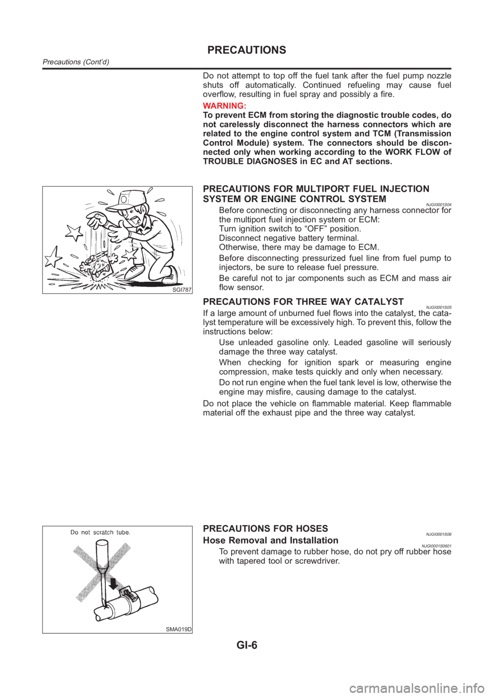
SGI787
PRECAUTIONS FOR MULTIPORT FUEL INJECTION
SYSTEM OR ENGINE CONTROL SYSTEM
NJGI0001S04Before connecting or disconnecting any harness connector for
the multiport fuel injection system or ECM:
Turn ignition switch to “OFF” position.
Disconnect negative battery terminal.
Otherwise, there may be damage to ECM.
Before disconnecting pressurized fuel line from fuel pump to
injectors, be sure to release fuel pressure.
Be careful not to jar components such as ECM and mass air
flow sensor.
PRECAUTIONS FOR THREE WAY CATALYSTNJGI0001S05If a large amount of unburned fuel flows into the catalyst, the cata-
lyst temperature will be excessively high. To prevent this, follow the
instructions below:
Use unleaded gasoline only. Leaded gasoline will seriously
damage the three way catalyst.
When checking for ignition spark or measuring engine
compression, make tests quickly and only when necessary.
Do not run engine when the fuel tank level is low, otherwise the
engine may misfire, causing damage to the catalyst.
Do not place the vehicle on flammable material. Keep flammable
material off the exhaust pipe and the three way catalyst.
SMA019D
PRECAUTIONS FOR HOSESNJGI0001S06Hose Removal and InstallationNJGI0001S0601To prevent damage to rubber hose, do not pry off rubber hose
with tapered tool or screwdriver.
PRECAUTIONS
Precautions (Cont’d)
GI-6
Page 55 of 3189

NEW TERMNEW ACRONYM /
ABBREVIATIONOLD TERM
Malfunction indicator MI Check engine light
Manifold absolute pressure MAP ***
Manifold absolute pressure sensor MAPS ***
Manifold differential pressure MDP ***
Manifold differential pressure sensor MDPS ***
Manifold surface temperature MST ***
Manifold surface temperature sensor MSTS ***
Manifold vacuum zone MVZ ***
Manifold vacuum zone sensor MVZS ***
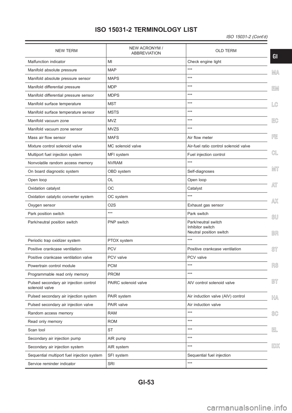
Mass air flow sensor MAFS Air flow meter
Mixture control solenoid valve MC solenoid valve Air-fuel ratio control solenoid valve
Multiport fuel injection system MFI system Fuel injection control
Nonvolatile random access memory NVRAM ***
On board diagnostic system OBD system Self-diagnoses
Open loop OL Open loop
Oxidation catalyst OC Catalyst
Oxidation catalytic converter system OC system ***
Oxygen sensor O2S Exhaust gas sensor
Park position switch *** Park switch
Park/neutral position switch PNP switch Park/neutral switch
Inhibitor switch
Neutral position switch
Periodic trap oxidizer system PTOX system ***
Positive crankcase ventilation PCV Positive crankcase ventilation
Positive crankcase ventilation valve PCV valve PCV valve
Powertrain control module PCM ***
Programmable read only memory PROM ***
Pulsed secondary air injection control
solenoid valvePAIRC solenoid valve AIV control solenoid valve
Pulsed secondary air injection system PAIR system Air induction valve (AIV) control
Pulsed secondary air injection valve PAIR valve Air induction valve
Random access memory RAM ***
Read only memory ROM ***
Scan tool ST ***
Secondary air injection pump AIR pump ***
Secondary air injection system AIR system ***
Sequential multiport fuel injection system SFI system Sequential fuel injection
Service reminder indicator SRI ***
MA
EM
LC
EC
FE
CL
MT
AT
AX
SU
BR
ST
RS
BT
HA
SC
EL
IDX
ISO 15031-2 TERMINOLOGY LIST
ISO 15031-2 (Cont’d)
GI-53
Page 92 of 3189
![NISSAN ALMERA N16 2003 Electronic Repair Manual EM-14
[QG]
AIR CLEANER AND AIR DUCT
AIR CLEANER AND AIR DUCT
PFP:16500
Removal and InstallationEBS00LQ1
REMOVAL
1. Remove air cleaner case assembly, air duct and resonator.
●Add marks as necessary f NISSAN ALMERA N16 2003 Electronic Repair Manual EM-14
[QG]
AIR CLEANER AND AIR DUCT
AIR CLEANER AND AIR DUCT
PFP:16500
Removal and InstallationEBS00LQ1
REMOVAL
1. Remove air cleaner case assembly, air duct and resonator.
●Add marks as necessary f](/manual-img/5/57350/w960_57350-91.png)
EM-14
[QG]
AIR CLEANER AND AIR DUCT
AIR CLEANER AND AIR DUCT
PFP:16500
Removal and InstallationEBS00LQ1
REMOVAL
1. Remove air cleaner case assembly, air duct and resonator.
●Add marks as necessary for easier installation.
2. Remove harness connector from mass air flow sensor.
3. Remove mass air flow sensor.
CAUTION:
Handle mass air flow sensor with following cares.
●Do not shock it.
●Do not disassembly it.
●Do not touch its sensor.
●Do not deform mass air flow sensor's wire mesh.
4. Remove left fender protector and resonator.
INSTALLATION
1. Attach each joint aligning marks put at removal. Screw clamps firmly.
2. Install in the reverse order of removal.
PBIC0533E
1. Air cleaner case (upper) 2. Resonator 3. Air duct
4. Mass air flow sensor 5. O-ring 6. Air cleaner case (lower)
7. Grommet 8. Air cleaner element 9. Bracket
Page 182 of 3189
![NISSAN ALMERA N16 2003 Electronic Repair Manual EM-104
[QG]
SERVICE DATA AND SPECIFICATIONS (SDS)
CONNECTING ROD BEARING
Standard Size
Unit: mm (in)
Undersize
Unit: mm (in)
Bearing Clearance
Unit: mm (in)
MISCELLANEOUS COMPONENTS
Unit: mm (in)
*: T NISSAN ALMERA N16 2003 Electronic Repair Manual EM-104
[QG]
SERVICE DATA AND SPECIFICATIONS (SDS)
CONNECTING ROD BEARING
Standard Size
Unit: mm (in)
Undersize
Unit: mm (in)
Bearing Clearance
Unit: mm (in)
MISCELLANEOUS COMPONENTS
Unit: mm (in)
*: T](/manual-img/5/57350/w960_57350-181.png)
EM-104
[QG]
SERVICE DATA AND SPECIFICATIONS (SDS)
CONNECTING ROD BEARING
Standard Size
Unit: mm (in)
Undersize
Unit: mm (in)
Bearing Clearance
Unit: mm (in)
MISCELLANEOUS COMPONENTS
Unit: mm (in)
*: Total indicator reading
Tightening TorqueEBS00LQQ
*1: Parts to be tightened in particular orders.
1)-: Order of tightening when tightening two or more times separately.
Unit: N·m (kg-m, ft-lb) / Unit: N·m (kg-m, in-lb)*2
Grade No. Thickness Identification color or number
0 1.503 - 1.506 (0.0592 - 0.0593) Block
1 1.506 - 1.509 (0.0593 - 0.0594) Red
2 1.509 - 1.512 (0.0594 - 0.0595) Green
Grade No. Thickness Identification color or number
0.08 (0.0031) 1.542 - 1.546 (0.0607 - 0.0609) —
0.12 (0.0047) 1.562 - 1.566 (0.0615 - 0.0617) —
0.25 (0.0098) 1.627 - 1.631 (0.0641 - 0.0642) —
Connecting rod bearing clear-
anceStandard 0.014 - 0.039 (0.0006 - 0.0015)
Limit 0.1 (0.004)
Flywheel runout [TIR*] Less than 0.1 (0.004)
Camshaft sprocket runout [TIR*] Less than 0.15 (0.0059)
Mass air flow sensor
8.4 - 10.8 (0.9 - 1.1, 75 - 95)*2
Resonator
3.8 - 4.5 (0.39 - 0.45, 34 - 39)*2
Air cleaner case lower
3.8 - 4.5 (0.39 - 0.46, 34 - 39)*2
Intake manifold16.7 - 23.5 (1.7 - 2.4, 13 - 17)
Intake manifold collector
7.0 - 9.5 (0.71 - 0.97, 62 - 84)*
2
Intake manifold support 16.7 - 23.5 (1.7 - 2.4, 13 - 17)
Electric throttle control actuator 17.7 - 21.6 (1.8 - 2.2, 13 - 15)
Exhaust manifold25.5 - 29.4 (2.6 - 2.9, 19 - 21)
Exhaust manifold cover
6.3 - 8.3 (0.64 - 0.85, 56 - 73)*
2
Heated oxygen sensor 58.8 - 78.4 (6.0 - 7.9, 44 - 57)
Ground nut79.4 (8.1, 59)
Oil pan
6.28 - 8.34 (0.64 - 0.85, 56 - 73)*
2
Oil pan drain plug29.4 - 39.2 ( 3.0 - 3.9, 22 - 28)
Oil strainer
6.28 - 8.34 (0.64 - 0.85, 56 - 73)*
2
Ignition coil
3.8 - 5.0 (0.38 - 0.51, 33 - 44)*2
Spark plug19.6 - 29.4 (2.0 - 3.0, 15 - 21)
*1 Fuel tube1) 11.8 - 13.8 (1.2 - 1.4, 9 - 10 )
2) 17 - 23 (1.7 - 2.4, 13 - 17)
Rocker cover
6.9 - 9.5 (0.70 - 0.97, 61 - 84)*
2
Page 335 of 3189

EC-5
C
D
E
F
G
H
I
J
K
L
M
ECA Wiring Diagram .................................................... 353
Diagnostic Procedure ........................................... 354
DTC P1706 PNP SWITCH ...................................... 356
Component Description ........................................ 356
CONSULT-II Reference Value in Data Monitor Mode
. 356
On Board Diagnosis Logic ................................... 356
DTC Confirmation Procedure ............................... 356
Overall Function Check ........................................ 357
Wiring Diagram .................................................... 358
Diagnostic Procedure ........................................... 359
DTC P1805 BRAKE SWITCH ................................ 360
Description ........................................................... 360
CONSULT-II Reference Value in Data Monitor Mode
. 360
On Board Diagnosis Logic ................................... 360
DTC Confirmation Procedure ............................... 360
Wiring Diagram .................................................... 361
Diagnostic Procedure ........................................... 362
Component Inspection ......................................... 364
IGNITION SIGNAL .................................................. 365
Component Description ........................................ 365
Wiring Diagram .................................................... 366
Diagnostic Procedure ........................................... 369
Component Inspection ......................................... 373
Removal and Installation ...................................... 374
INJECTOR CIRCUIT ............................................... 375
Component Description ........................................ 375
CONSULT-II Reference Value in Data Monitor Mode
. 375
Wiring Diagram .................................................... 376
Diagnostic Procedure ........................................... 377
Component Inspection ......................................... 380
Removal and Installation ...................................... 380
FUEL PUMP CIRCUIT ............................................ 381
Description ........................................................... 381
CONSULT-II Reference Value in Data Monitor Mode
. 381
Wiring Diagram .................................................... 382
Diagnostic Procedure ........................................... 383
Component Inspection ......................................... 385
Removal and Installation ...................................... 386
REFRIGERANT PRESSURE SENSOR ................. 387
Component Description ........................................ 387
Wiring Diagram .................................................... 388
Diagnostic Procedure ........................................... 389
Removal and Installation ...................................... 391
ELECTRICAL LOAD SIGNAL ................................ 392
Description ...................................................
........ 392
CONSULT-II Reference Value in Data Monitor Mode
. 392
Wiring Diagram .................................................... 393
Diagnostic Procedure ........................................... 394
MI & DATA LINK CONNECTORS .......................... 397
Wiring Diagram—LHD Models ............................. 397
Wiring Diagram—RHD Models ............................ 398
EVAPORATIVE EMISSION SYSTEM ..................... 399
Description ........................................................... 399
Component Inspection ......................................... 401POSITIVE CRANKCASE VENTILATION ...............402
Description ............................................................402
Component Inspection ..........................................402
SERVICE DATA AND SPECIFICATIONS (SDS) ....404
Fuel Pressure .......................................................404
Idle Speed and Ignition Timing .............................404
Calculated Load Value ..........................................404
Mass Air Flow Sensor ...........................................404
Intake Air Temperature Sensor .............................404
Engine Coolant Temperature Sensor ...................404
Heated Oxygen Sensor 1 Heater .........................404
Heated Oxygen sensor 2 Heater ..........................404
Crankshaft Position Sensor (POS) .......................404
Camshaft Position Sensor (PHASE) ....................404
Throttle Control Motor ...........................................405
Injector ..................................................................405
Fuel Pump ............................................................405
QG (WITHOUT EURO-OBD)
INDEX FOR DTC .....................................................406
Alphabetical Index ................................................406
DTC No. Index ......................................................407
PRECAUTIONS ......................................................409
Precautions for Supplemental Restraint System
(SRS) “AIR BAG” and “SEAT BELT PRE-TEN-
SIONER” ...............................................................409
On Board Diagnostic (OBD) System of Engine ....409
Precaution ............................................................409
Wiring Diagrams and Trouble Diagnosis ..............412
PREPARATION .......................................................413
Special Service Tools ...........................................413
Commercial Service Tools ....................................413
ENGINE CONTROL SYSTEM ................................415
System Diagram ...................................................415
Vacuum Hose Drawing .........................................416
System Chart ........................................................417
Multiport Fuel Injection (MFI) System ...................417
Electronic Ignition (EI) System .............................419
Air Conditioning Cut Control .................................420
Fuel Cut Control (at No Load and High Engine
Speed) ..................................................................421
CAN Communication ............................................421
BASIC SERVICE PROCEDURE .............................424
Idle Speed and Ignition Timing Check ..................424
Accelerator Pedal Released Position Learning ....425
Throttle Valve Closed Position Learning ...............425
Idle Air Volume Learning ......................................425
Fuel Pressure Check ............................................427
ON BOARD DIAGNOSTIC (OBD) SYSTEM ..........429
Introduction ...........................................................429
Two Trip Detection Logic ......................................429
Emission-related Diagnostic Information ..............429
NATS (Nissan Anti-theft System) .........................431
Malfunction Indicator (MI) .....................................432
TROUBLE DIAGNOSIS ..........................................436
Trouble Diagnosis Introduction .............................436
DTC Inspection Priority Chart ...............................440
Fail-safe Chart ......................................................441
Page 339 of 3189

EC-9
C
D
E
F
G
H
I
J
K
L
M
ECA EVAPORATIVE EMISSION SYSTEM ..................... 717
Description ........................................................... 717
Component Inspection ......................................... 719
POSITIVE CRANKCASE VENTILATION ............... 720
Description ........................................................... 720
Component Inspection ......................................... 720
SERVICE DATA AND SPECIFICATIONS (SDS) .... 722
Fuel Pressure ....................................................... 722
Idle Speed and Ignition Timing ............................. 722
Calculated Load Value ......................................... 722Mass Air Flow Sensor ...........................................722
Intake Air Temperature Sensor .............................722
Engine Coolant Temperature Sensor ...................722
Heated Oxygen Sensor 1 Heater .........................722
Heated Oxygen sensor 2 Heater ..........................722
Crankshaft Position Sensor (POS) .......................722
Camshaft Position Sensor (PHASE) ....................722
Throttle Control Motor ...........................................723
Injector ..................................................................723
Fuel Pump ............................................................723
Page 346 of 3189
![NISSAN ALMERA N16 2003 Electronic Repair Manual EC-16
[QG (WITH EURO-OBD)]
PRECAUTIONS
●Do not disassemble ECM.
●If battery cable is disconnected, the memory will return to
the initial ECM values.
The ECM will now start to self-c NISSAN ALMERA N16 2003 Electronic Repair Manual EC-16
[QG (WITH EURO-OBD)]
PRECAUTIONS
●Do not disassemble ECM.
●If battery cable is disconnected, the memory will return to
the initial ECM values.
The ECM will now start to self-c](/manual-img/5/57350/w960_57350-345.png)
EC-16
[QG (WITH EURO-OBD)]
PRECAUTIONS
●Do not disassemble ECM.
●If battery cable is disconnected, the memory will return to
the initial ECM values.
The ECM will now start to self-control at its initial values.
Engine operation can vary slightly when the cable is dis-
connected. However, this is not an indication of a malfunc-
tion. Do not replace parts because of a slight variation.
●When connecting ECM harness connector, fasten it
securely with levers as far as they will go as shown at right.
●When connecting or disconnecting pin connectors into or
from ECM, take care not to damage pin terminals (bend or
break).
Make sure that there are not any bends or breaks on ECM
pin terminal, when connecting pin connectors.
●Securely connect ECM harness connectors.
A poor connection can cause an extremely high (surge)
voltage to develop in coil and condenser, thus resulting in
damage to ICs.
●Keep engine control system harness at least 10 cm (4 in)
away from adjacent harness, to prevent engine control sys-
tem malfunctions due to receiving external noise, degraded
operation of ICs, etc.
●Keep engine control system parts and harness dry.
●Before replacing ECM, perform “ECM Terminals and Refer-
ence Value” inspection and make sure ECM functions prop-
erly. Refer to EC-80, "
ECM Terminals and Reference Value" .
●Handle mass air flow sensor carefully to avoid damage.
●Do not disassemble mass air flow sensor.
●Do not clean mass air flow sensor with any type of deter-
gent.
●Do not disassemble electric throttle control actuator.
●Even a slight leak in the air intake system can cause seri-
ous incidents.
●Do not shock or jar the camshaft position sensor (PHASE),
crankshaft position sensor (POS).
PBIB1164E
MBIB0145E
PBIB0090E
MEF040D
Page 353 of 3189
![NISSAN ALMERA N16 2003 Electronic Repair Manual ENGINE CONTROL SYSTEM
EC-23
[QG (WITH EURO-OBD)]
C
D
E
F
G
H
I
J
K
L
MA
EC
System ChartEBS00K34
*1: This sensor is not used to control the engine system under normal conditions.
*2: The signals are se NISSAN ALMERA N16 2003 Electronic Repair Manual ENGINE CONTROL SYSTEM
EC-23
[QG (WITH EURO-OBD)]
C
D
E
F
G
H
I
J
K
L
MA
EC
System ChartEBS00K34
*1: This sensor is not used to control the engine system under normal conditions.
*2: The signals are se](/manual-img/5/57350/w960_57350-352.png)
ENGINE CONTROL SYSTEM
EC-23
[QG (WITH EURO-OBD)]
C
D
E
F
G
H
I
J
K
L
MA
EC
System ChartEBS00K34
*1: This sensor is not used to control the engine system under normal conditions.
*2: The signals are sent to the ECM through CAN communication line.
*3: The output signals are sent from the ECM through CAN communication line.
Multiport Fuel Injection (MFI) SystemEBS00K35
INPUT/OUTPUT SIGNAL CHART
*1: Under normal conditions, this sensor is not for engine control operation.
*2: This signal is sent to the ECM through CAN communication line.
*3: ECM determines the start signal status by the signals of engine speed and battery voltage.
SYSTEM DESCRIPTION
The amount of fuel injected from the fuel injector is determined by the ECM. The ECM controls the length of
time the valve remains open (injection pulse duration). The amount of fuel injected is a program value in the
Input (Sensor) ECM Function Output (Actuator)
●Camshaft position sensor (PHASE)
●Crankshaft position sensor (POS)
●Mass air flow sensor
●Engine coolant temperature sensor
●Heated oxygen sensor 1
●Throttle position sensor
●Accelerator pedal position sensor
●Park/neutral position (PNP) switch
●Intake air temperature sensor
●Power steering pressure sensor
●Ignition switch
●Stop lamp switch
●Battery voltage
●Knock sensor
●Refrigerant pressure sensor
●Heated oxygen sensor 2*1
●TCM (Transmission control module)*2
●Air conditioner switch*2
●Vehicle speed signal*2
●Electrical load signal*2
Fuel injection & mixture ratio control Fuel injectors
Electronic ignition system Power transistor
Fuel pump control Fuel pump relay
On board diagnostic system
MI (On the instrument panel)
*3
Intake valve timing controlIntake valve timing control solenoid
valve
Heated oxygen sensor 1 heater control Heated oxygen sensor 1 heater
Heated oxygen sensor 2 heater control Heated oxygen sensor 2 heater
EVAP canister purge flow controlEVAP canister purge volume control
solenoid valve
Air conditioning cut control
Air conditioner relay
*3
Cooling fan control
Cooling fan relay*3
Sensor Input Signal to ECM ECM Function Actuator
Crankshaft position sensor (POS)
Camshaft position sensor (PHASE)Engine speed
*3 and piston position
Fuel injection & mixture
ratio controlFuel injectors Mass air flow sensor Amount of intake air
Engine coolant temperature sensor Engine coolant temperature
Heated oxygen sensor 1 Density of oxygen in exhaust gas
Throttle position sensor Throttle position
Accelerator pedal position sensor Accelerator pedal position
Park/neutral position (PNP) switch Gear position
Knock sensor Engine knocking condition
Battery
Battery voltage
*3
Power steering pressure sensor Power steering operation
Heated oxygen sensor 2
*1Density of oxygen in exhaust gas
Vehicle speed signal
*2Vehicle speed
Air conditioner switch
*2Air conditioner operation