2003 NISSAN ALMERA N16 door motor
[x] Cancel search: door motorPage 1982 of 3189
ATC-2
Discharge Air Flow ................................................. 27
System Description ................................................. 28
SWITCHES AND THEIR CONTROL FUNCTION ... 28
TROUBLE DIAGNOSIS ............................................ 29
How to Perform Trouble Diagnoses for Quick and
Accurate Repair ...................................................... 29
WORK FLOW ...................................................... 29
SYMPTOM TABLE .............................................. 29
Component Parts and Harness Connector Location ... 30
ENGINE COMPARTMENT .................................. 30
PASSENGER COMPARTMENT .......................... 31
Circuit Diagram ....................................................... 32
Wiring Diagram ....................................................... 33
Auto Amp. Terminals and Reference Value ............ 40
PIN CONNECTOR TERMINAL LAYOUT ............ 40
AUTO AMP. INSPECTION TABLE ...................... 40
Self-diagnosis Function .......................................... 42
DESCRIPTION .................................................... 42
FUNCTION CONFIRMATION PROCEDURE ...... 43
AUXILIARY MECHANISM: TEMPERATURE
SETTING TRIMMER ........................................... 49
Operational Check .................................................. 51
CHECKING MEMORY FUNCTION ..................... 51
CHECKING BLOWER ......................................... 51
CHECKING DISCHARGE AIR ............................ 52
CHECKING RECIRCULATION ............................ 53
CHECKING FRESH SWITCH ............................. 53
CHECKING TEMPERATURE DECREASE ......... 53
CHECKING TEMPERATURE INCREASE .......... 53
CHECKING AUTO MODE ................................... 54
Power Supply and Ground Circuit for Auto Amp. ... 55
INSPECTION FLOW ........................................... 55
COMPONENT DESCRIPTION ............................ 55
DIAGNOSTIC PROCEDURE FOR A/C SYSTEM ... 56
LAN System Circuit ............................................. ... 57
DIAGNOSTIC PROCEDURE FOR LAN SYS-
TEM CIRCUIT ..................................................... 57
Mode Door Motor Circuit ........................................ 59
INSPECTION FLOW ........................................... 60
SYSTEM DESCRIPTION .................................... 61
COMPONENT DESCRIPTION ............................ 62
DIAGNOSTIC PROCEDURE FOR MODE
DOOR .................................................................. 62
Air Mix Door Motor Circuit ...................................... 63
INSPECTION FLOW ........................................... 63
SYSTEM DESCRIPTION .................................... 64
COMPONENT DESCRIPTION ............................ 65
DIAGNOSTIC PROCEDURE FOR AIR MIX
DOOR MOTOR ................................................... 65
Intake Door Motor Circuit ........................................ 66
INSPECTION FLOW ........................................... 66
SYSTEM DESCRIPTION .................................
... 67
COMPONENT DESCRIPTION ............................ 67
DIAGNOSTIC PROCEDURE FOR INTAKE
DOOR MOTOR ................................................... 68
Blower Motor Circuit ............................................... 69
INSPECTION FLOW ........................................... 69
SYSTEM DESCRIPTION .................................... 70
COMPONENT DESCRIPTION ............................ 71DIAGNOSTIC PROCEDURE FOR BLOWER
MOTOR ................................................................ 71
COMPONENT INSPECTION ............................... 74
Magnet Clutch Circuit .............................................. 75
INSPECTION FLOW ............................................ 75
SYSTEM DESCRIPTION ..................................... 76
DIAGNOSTIC PROCEDURE FOR MAGNET
CLUTCH (WITH CAN SYSTEM) ......................... 76
DIAGNOSTIC PROCEDURE FOR MAGNET
CLUTCH (YD ENGINE WITHOUT COMMON
RAIL) .................................................................... 81
COMPONENT INSPECTION ............................... 85
Insufficient Cooling .................................................. 86
INSPECTION FLOW ............................................ 86
PERFORMANCE TEST DIAGNOSES ................ 88
PERFORMANCE CHART .................................... 90
TROUBLE DIAGNOSES FOR UNUSUAL PRES-
SURE ................................................................... 92
Insufficient Heating ................................................. 95
INSPECTION FLOW ............................................ 95
Noise ....................................................................... 97
INSPECTION FLOW ............................................ 97
Self-diagnosis ......................................................... 98
INSPECTION FLOW ............................................ 98
Memory Function .................................................... 99
INSPECTION FLOW ............................................ 99
Ambient Sensor Circuit .........................................100
COMPONENT DESCRIPTION ..........................100
AMBIENT TEMPERATURE INPUT PROCESS .100
DIAGNOSTIC PROCEDURE FOR AMBIENT
SENSOR ............................................................100
COMPONENT INSPECTION .............................102
In-vehicle Sensor Circuit .......................................102
COMPONENT DESCRIPTION ..........................102
DIAGNOSTIC PROCEDURE FOR IN-VEHICLE
SENSOR ............................................................103
COMPONENT INSPECTION .............................104
Sunload Sensor Circuit .........................................105
COMPONENT DESCRIPTION ..........................105
SUNLOAD INPUT PROCESS ...........................105
DIAGNOSTIC PROCEDURE FOR SUNLOAD
SENSOR ............................................................105
COMPONENT INSPECTION .............................107
Intake Sensor Circuit .............................................108
COMPONENT DESCRIPTION ..........................108
DIAGNOSTIC PROCEDURE FOR INTAKE SEN-
SOR ...................................................................108
Multiplex Communication Circuit ...........................109
DIAGNOSTIC PROCEDURE FOR MULTIPLEX
COMMUNICATION CIRCUIT ............................109
CONTROLLER ........................................................113
Removal and Installation .......................................113
AUTO AMP ..............................................................114
REMOVAL AND INSTALLATION ..........................114
AMBIENT SENSOR ................................................115
Removal and Installation .......................................115
IN-VEHICLE SENSOR ............................................116
Removal and Installation .......................................116
Page 1983 of 3189
ATC-3
C
D
E
F
G
H
I
K
L
MA
B
AT C SUNLOAD SENSOR ...............................................117
Removal and Installation ....................................... 117
INTAKE SENSOR CIRCUIT ....................................118
Removal and Installation ....................................... 118
BLOWER UNIT ........................................................119
Removal and Installation ....................................... 119
REMOVAL .......................................................... 119
INSTALLATION .................................................. 119
Disassembly and Assembly .................................. 119
BLOWER MOTOR .................................................. 120
Removal and Installation ...................................... 120
INTAKE DOOR MOTOR ......................................... 121
Removal and Installation ...................................... 121
HEATER & COOLING UNIT ASSEMBLY .............. 122
Removal and Installation ...................................... 122
REMOVAL ......................................................... 122
INSTALLATION ................................................. 123
Disassembly and Assembly ................................. 123
MODE DOOR MOTOR ........................................... 125
Removal and Installation ...................................... 125
AIR MIX DOOR MOTOR ......................................... 126
Removal and Installation ...................................... 126
FAN CONTROL AMPLIFIER .................................. 127
Removal and Installation ...................................... 127
VENTILATION AIR FILTER .................................... 128
Removal and Installation ...................................... 128
FUNCTION ........................................................ 128
REPLACEMENT TIMING .................................. 128
REPLACEMENT AND PROCEDURES ............ 128
HEATER CORE ...................................................... 129
Removal and Installation ...................................... 129
DUCTS AND GRILLES .......................................... 130
Removal and Installation ...................................... 130
VENTILATOR DUCT, DEFROSTER NOZZLE
AND DEFROSTER DUCTS .............................. 130
CENTER VENTILATOR GRILLE ...................... 130
SIDE VENTILATOR GRILLE ............................. 130
FOOT DUCT ..................................................... 130
FLOOR DUCT ................................................... 131
REFRIGERANT LINES ........................................... 132
HFC-134a (R-134a) Service Procedure ............... 132
SETTING OF SERVICE TOOLS AND EQUIP-
MENT ................................................................ 132Components .........................................................134
Compressor ..........................................................136
REMOVAL .........................................................136
INSTALLATION .................................................137
Compressor Clutch .............................................. .138
REMOVAL .........................................................138
INSTALLATION .................................................139
Low-pressure Flexible Hose .................................141
REMOVAL .........................................................141
INSTALLATION .................................................141
High-pressure Flexible Hose ................................141
REMOVAL .........................................................141
INSTALLATION .................................................142
High-pressure Pipe ...............................................142
REMOVAL .........................................................142
INSTALLATION .................................................142
Refrigerant Pressure Sensor ................................142
REMOVAL AND INSTALLATION ......................142
Dual-pressure Switch ...........................................143
REMOVAL AND INSTALLATION ......................143
Condenser Assembly ...........................................143
REMOVAL .........................................................143
INSTALLATION .................................................143
Evaporator ............................................................144
REMOVAL .........................................................144
INSTALLATION .................................................144
Expansion Valve ...................................................144
REMOVAL .........................................................144
INSTALLATION .................................................144
Checking for Refrigerant Leaks ............................145
Checking System for Leaks Using the Fluorescent
Leak Detector .......................................................145
Dye Injection .........................................................146
Electronic Refrigerant Leak Detector ....................146
PRECAUTIONS FOR HANDLING LEAK
DETECTOR .......................................................146
CHECKING PROCEDURE ...............................147
SERVICE DATA AND SPECIFICATIONS (SDS) ....149
Compressor ..........................................................149
Lubricant ...............................................................149
Refrigerant ............................................................149
Engine Idling Speed .............................................149
Belt Tension ..........................................................149
Page 2002 of 3189
ATC-22
AIR CONDITIONER CONTROL
AIR CONDITIONER CONTROL
PFP:27500
Overview Air Conditioner LAN Control SystemEJS001Z5
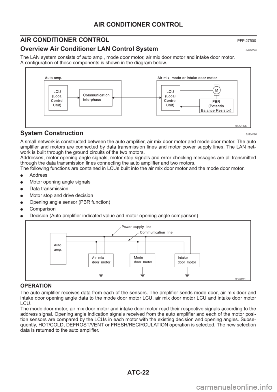
The LAN system consists of auto amp., mode door motor, air mix door motor and intake door motor.
A configuration of these components is shown in the diagram below.
System ConstructionEJS001Z6
A small network is constructed between the auto amplifier, air mix door motor and mode door motor. The auto
amplifier and motors are connected by data transmission lines and motor power supply lines. The LAN net-
work is built through the ground circuits of the two motors.
Addresses, motor opening angle signals, motor stop signals and error checking messages are all transmitted
through the data transmission lines connecting the auto amplifier and two motors.
The following functions are contained in LCUs built into the air mix door motor and the mode door motor.
●Address
●Motor opening angle signals
●Data transmission
●Motor stop and drive decision
●Opening angle sensor (PBR function)
●Comparison
●Decision (Auto amplifier indicated value and motor opening angle comparison)
OPERATION
The auto amplifier receives data from each of the sensors. The amplifier sends mode door, air mix door and
intake door opening angle data to the mode door motor LCU, air mix door motor LCU and intake door motor
LCU.
The mode door motor, air mix door motor and intake door motor read their respective signals according to the
address signal. Opening angle indication signals received from the auto amplifier and each of the motor posi-
tion sensors are compared by the LCUs in each motor with the existing decision and opening angles. Subse-
quently, HOT/COLD, DEFROST/VENT or FRESH/RECIRCULATION operation is selected. The new selection
data is returned to the auto amplifier.
RJIA0480E
RHA350H
Page 2003 of 3189
AIR CONDITIONER CONTROL
ATC-23
C
D
E
F
G
H
I
K
L
MA
B
AT C
TRANSMISSION DATA AND TRANSMISSION ORDER
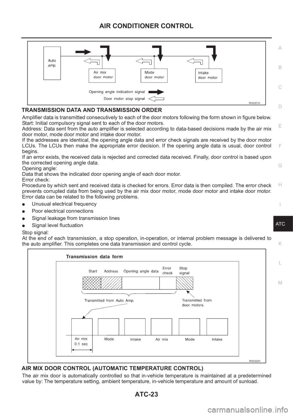
Amplifier data is transmitted consecutively to each of the door motors following the form shown in figure below.
Start: Initial compulsory signal sent to each of the door motors.
Address: Data sent from the auto amplifier is selected according to data-based decisions made by the air mix
door motor, mode door motor and intake door motor.
If the addresses are identical, the opening angle data and error check signals are received by the door motor
LCUs. The LCUs then make the appropriate error decision. If the opening angle data is usual, door control
begins.
If an error exists, the received data is rejected and corrected data received. Finally, door control is based upon
the corrected opening angle data.
Opening angle:
Data that shows the indicated door opening angle of each door motor.
Error check:
Procedure by which sent and received data is checked for errors. Error data is then compiled. The error check
prevents corrupted data from being used by the air mix door motor, mode door motor and intake door motor.
Error data can be related to the following problems.
●Unusual electrical frequency
●Poor electrical connections
●Signal leakage from transmission lines
●Signal level fluctuation
Stop signal:
At the end of each transmission, a stop operation, in-operation, or internal problem message is delivered to
the auto amplifier. This completes one data transmission and control cycle.
AIR MIX DOOR CONTROL (AUTOMATIC TEMPERATURE CONTROL)
The air mix door is automatically controlled so that in-vehicle temperature is maintained at a predetermined
value by: The temperature setting, ambient temperature, in-vehicle temperature and amount of sunload.
RHA351H
RHA352H
Page 2004 of 3189
ATC-24
AIR CONDITIONER CONTROL
FAN SPEED CONTROL
Blower speed is automatically controlled based on temperature setting, ambient temperature, in-vehicle tem-
perature, intake temperature, amount of sunload and air mix door position.
With FAN switch set to AUTO, the blower motor starts to gradually increase air flow volume.
When engine coolant temperature is low, the blower motor operation is delayed to prevent cool air from flow-
ing.
INTAKE DOOR CONTROL
The intake doors are automatically controlled by: The temperature setting, ambient temperature, in-vehicle
temperature, intake temperature, amount of sunload and ON-OFF operation of the compressor.
OUTLET DOOR CONTROL
The outlet door is automatically controlled by: The temperature setting, ambient temperature, in-vehicle tem-
perature, intake temperature and amount of sunload.
MAGNET CLUTCH CONTROL
The ECM controls compressor operation using input signals from the refrigerant pressure sensor (with QG
engine), throttle position sensor and auto amplifier.
SELF-DIAGNOSTIC SYSTEM
The self-diagnostic system is built into the auto amplifier (LCU) to quickly locate the cause of problems.
Overview of Control systemEJS001Z7
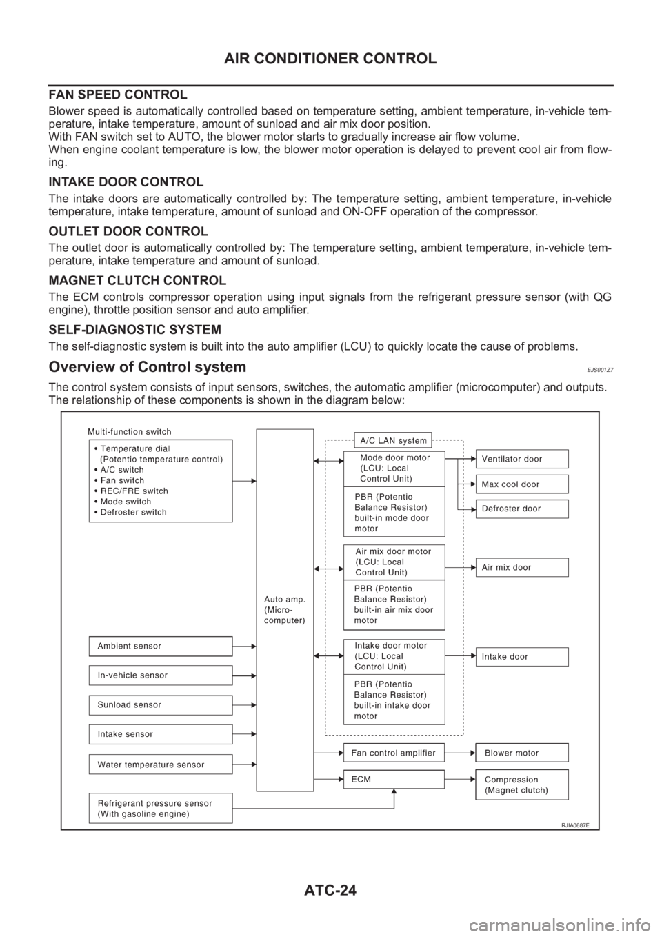
The control system consists of input sensors, switches, the automatic amplifier (microcomputer) and outputs.
The relationship of these components is shown in the diagram below:
RJIA0687E
Page 2009 of 3189
TROUBLE DIAGNOSIS
ATC-29
C
D
E
F
G
H
I
K
L
MA
B
AT C
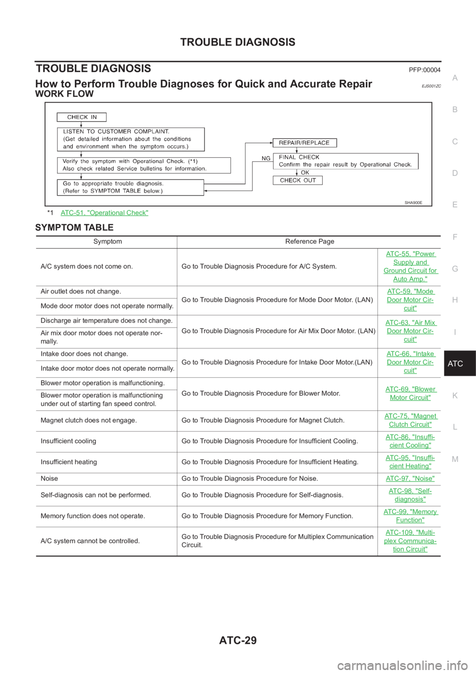
TROUBLE DIAGNOSISPFP:00004
How to Perform Trouble Diagnoses for Quick and Accurate RepairEJS001ZC
WORK FLOW
SYMPTOM TABLE
*1AT C - 5 1 , "Operational Check"
SHA900E
Symptom Reference Page
A/C system does not come on. Go to Trouble Diagnosis Procedure for A/C System.ATC-55, "
Power
Supply and
Ground Circuit for
Auto Amp."
Air outlet does not change.
Go to Trouble Diagnosis Procedure for Mode Door Motor. (LAN)AT C - 5 9 , "Mode
Door Motor Cir-
cuit"Mode door motor does not operate normally.
Discharge air temperature does not change.
Go to Trouble Diagnosis Procedure for Air Mix Door Motor. (LAN)ATC-63, "
Air Mix
Door Motor Cir-
cuit"Air mix door motor does not operate nor-
mally.
Intake door does not change.
Go to Trouble Diagnosis Procedure for Intake Door Motor.(LAN)AT C - 6 6 , "
Intake
Door Motor Cir-
cuit"Intake door motor does not operate normally.
Blower motor operation is malfunctioning.
Go to Trouble Diagnosis Procedure for Blower Motor.ATC-69, "
Blower
Motor Circuit"Blower motor operation is malfunctioning
under out of starting fan speed control.
Magnet clutch does not engage. Go to Trouble Diagnosis Procedure for Magnet Clutch.AT C - 7 5 , "
Magnet
Clutch Circuit"
Insufficient cooling Go to Trouble Diagnosis Procedure for Insufficient Cooling.AT C - 8 6 , "Insuffi-
cient Cooling"
Insufficient heating Go to Trouble Diagnosis Procedure for Insufficient Heating.AT C - 9 5 , "Insuffi-
cient Heating"
Noise Go to Trouble Diagnosis Procedure for Noise.ATC-97, "Noise"
Self-diagnosis can not be performed. Go to Trouble Diagnosis Procedure for Self-diagnosis.AT C - 9 8 , "Self-
diagnosis"
Memory function does not operate. Go to Trouble Diagnosis Procedure for Memory Function.AT C - 9 9 , "Memory
Function"
A/C system cannot be controlled.Go to Trouble Diagnosis Procedure for Multiplex Communication
Circuit.ATC-109, "
Multi-
plex Communica-
tion Circuit"
Page 2021 of 3189
TROUBLE DIAGNOSIS
ATC-41
C
D
E
F
G
H
I
K
L
MA
B
AT C
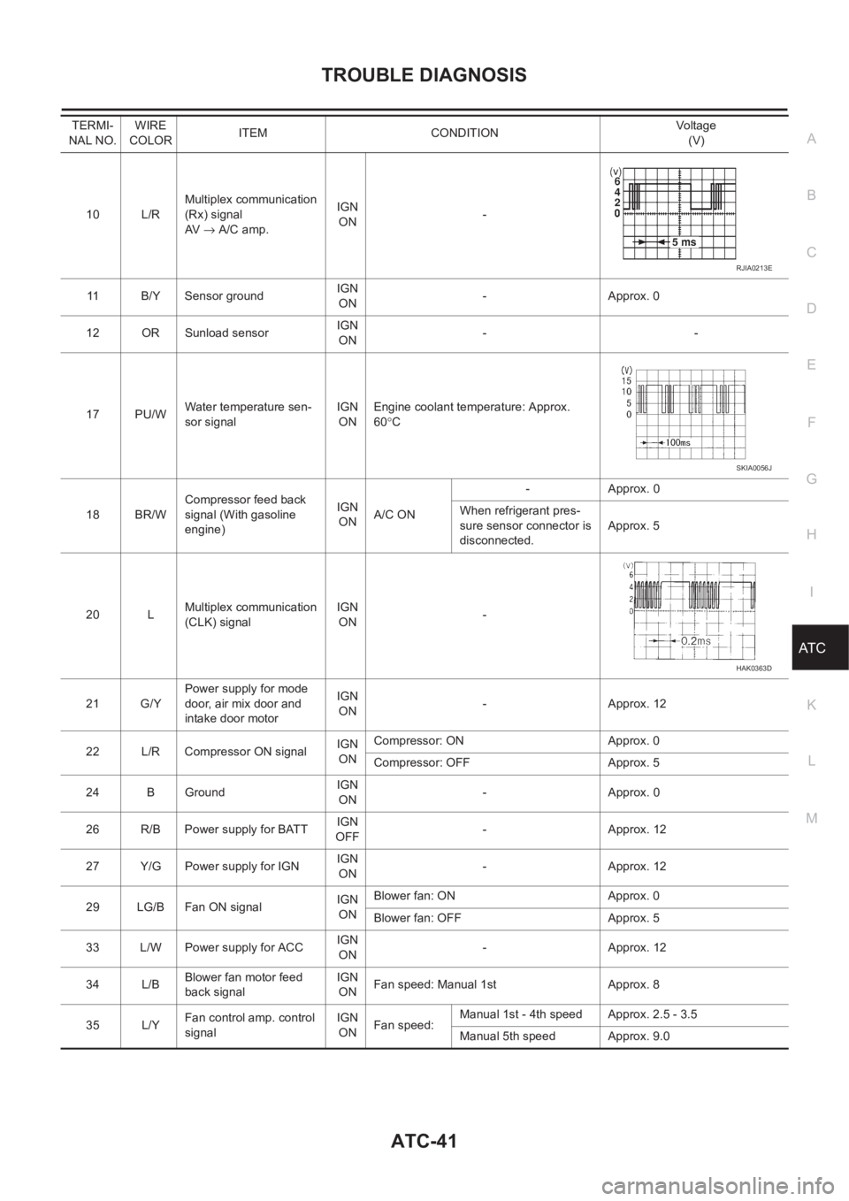
10 L/RMultiplex communication
(Rx) signal
AV → A/C amp.IGN
ON-
11 B/Y Sensor ground IGN
ON-Approx. 0
12 OR Sunload sensorIGN
ON--
17 PU/WWater temperature sen-
sor signalIGN
ONEngine coolant temperature: Approx.
60°C
18 BR/WCompressor feed back
signal (With gasoline
engine)IGN
ONA/C ON-Approx. 0
When refrigerant pres-
sure sensor connector is
disconnected.Approx. 5
20 LMultiplex communication
(CLK) signalIGN
ON-
21 G/YPower supply for mode
door, air mix door and
intake door motorIGN
ON-Approx. 12
22 L/R Compressor ON signalIGN
ONCompressor: ON Approx. 0
Compressor: OFF Approx. 5
24 B GroundIGN
ON-Approx. 0
26 R/B Power supply for BATTIGN
OFF-Approx. 12
27 Y/G Power supply for IGNIGN
ON-Approx. 12
29 LG/B Fan ON signalIGN
ONBlower fan: ON Approx. 0
Blower fan: OFF Approx. 5
33 L/W Power supply for ACCIGN
ON-Approx. 12
34 L/BBlower fan motor feed
back signalIGN
ONFan speed: Manual 1st Approx. 8
35 L/YFan control amp. control
signalIGN
ONFan speed:Manual 1st - 4th speed Approx. 2.5 - 3.5
Manual 5th speed Approx. 9.0 TERMI-
NAL NO.WIRE
COLORITEM CONDITIONVo lta g e
(V)
RJIA0213E
SKIA0056J
HAK0363D
Page 2022 of 3189
ATC-42
TROUBLE DIAGNOSIS
Self-diagnosis Function
EJS001ZH
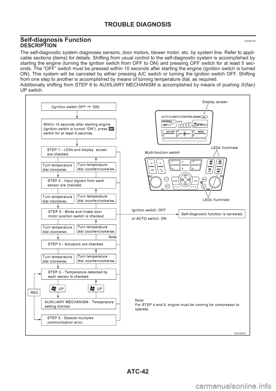
DESCRIPTION
The self-diagnostic system diagnoses sensors, door motors, blower motor, etc. by system line. Refer to appli-
cable sections (items) for details. Shifting from usual control to the self-diagnostic system is accomplished by
starting the engine (turning the ignition switch from OFF to ON) and pressing OFF switch for at least 5 sec-
onds. The “OFF” switch must be pressed within 10 seconds after starting the engine (ignition switch is turned
ON). This system will be canceled by either pressing A/C switch or turning the ignition switch OFF. Shifting
from one step to another is accomplished by means of turning temperature dial, as required.
Additionally shifting from STEP 6 to AUXILIARY MECHANISM is accomplished by means of pushing (fan)
UP switch.
RJIA1681E