Page 2026 of 3189

ATC-46
TROUBLE DIAGNOSIS
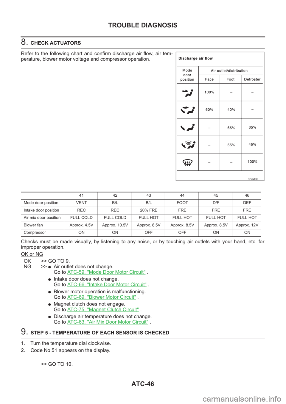
8. CHECK ACTUATORS
Refer to the following chart and confirm discharge air flow, air tem-
perature, blower motor voltage and compressor operation.
Checks must be made visually, by listening to any noise, or by touching air outlets with your hand, etc. for
improper operation.
OK or NG
OK >> GO TO 9.
NG >>
●Air outlet does not change.
Go to AT C - 5 9 , "
Mode Door Motor Circuit" .
●Intake door does not change.
Go to AT C - 6 6 , "
Intake Door Motor Circuit" .
●Blower motor operation is malfunctioning.
Go to AT C - 6 9 , "
Blower Motor Circuit" .
●Magnet clutch does not engage.
Go to AT C - 7 5 , "
Magnet Clutch Circuit" .
●Discharge air temperature does not change.
Go to AT C - 6 3 , "
Air Mix Door Motor Circuit" .
9. STEP 5 - TEMPERATURE OF EACH SENSOR IS CHECKED
1. Turn the temperature dial clockwise.
2. Code No.51 appears on the display.
>> GO TO 10.
RHA280I
41 42 43 44 45 46
Mode door position VENT B/L B/L FOOT D/F DEF
Intake door position REC REC 20% FRE FRE FRE FRE
Air mix door position FULL COLD FULL COLD FULL HOT FULL HOT FULL HOTFULL HOT
Blower fan Approx. 4.5V Approx. 10.5V Approx. 8.5V Approx. 8.5V Approx. 8.5V Approx. 12V
Compressor ON ON OFF OFF ON ON
Page 2028 of 3189
ATC-48
TROUBLE DIAGNOSIS
14. CHECK MALFUNCTIONING SENSOR
Refer to the following chart for malfunctioning code No.
(If two or more sensors malfunction, corresponding code Nos. blink respectively two times.)
*1: Conduct self-diagnosis STEP 2 under sunshine.
When conducting indoors, aim a light (more than 60W) at sunload sensor, otherwise Code No.25 will indicate
despite that sunload sensor is functioning properly.
*2: ATC-100, "
Ambient Sensor Circuit" .
*3: ATC-102, "
In-vehicle Sensor Circuit" .
*4: ATC-108, "
Intake Sensor Circuit" .
*5: ATC-105, "
Sunload Sensor Circuit" .
*6: AT C - 6 3 , "
Air Mix Door Motor Circuit" .
>> INSPECTION END
Code No. Malfunctioning sensor (Including circuits) Reference page
21 / -21 Ambient sensor *2
22 / -22 In-vehicle sensor *3
24 / -24 Intake sensor *4
25 / -25 Sunload sensor *5
26 / -26 Air mix door motor (LCU) PBR *6
RJIA0227E
Page 2029 of 3189

TROUBLE DIAGNOSIS
ATC-49
C
D
E
F
G
H
I
K
L
MA
B
AT C
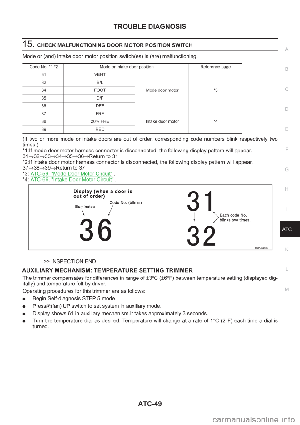
15.CHECK MALFUNCTIONING DOOR MOTOR POSITION SWITCH
Mode or (and) intake door motor position switch(es) is (are) malfunctioning.
(If two or more mode or intake doors are out of order, corresponding code numbers blink respectively two
times.)
*1:If mode door motor harness connector is disconnected, the following display pattern will appear.
31→32→33→34→35→36→Return to 31
*2:If intake door motor harness connector is disconnected, the following display pattern will appear.
37→38→39→Return to 37
*3: AT C - 5 9 , "
Mode Door Motor Circuit" .
*4: AT C - 6 6 , "
Intake Door Motor Circuit" .
>> INSPECTION END
AUXILIARY MECHANISM: TEMPERATURE SETTING TRIMMER
The trimmer compensates for differences in range of ±3°C (±6°F) between temperature setting (displayed dig-
itally) and temperature felt by driver.
Operating procedures for this trimmer are as follows:
●Begin Self-diagnosis STEP 5 mode.
●Press (fan) UP switch to set system in auxiliary mode.
●Display shows 61 in auxiliary mechanism.It takes approximately 3 seconds.
●Turn the temperature dial as desired. Temperature will change at a rate of 1°C (2°F) each time a dial is
turned.
Code No. *1 *2 Mode or intake door position Reference page
31 VENT
Mode door motor *3 32 B/L
34 FOOT
35 D/F
36 DEF
37 FRE
Intake door motor *4 38 20% FRE
39 REC
RJIA0228E
Page 2032 of 3189
ATC-52
TROUBLE DIAGNOSIS
CHECKING DISCHARGE AIR
1. Press mode switch four times and DEF button.
2. Each position indicator should change shape.
3. Confirm that discharge air comes out according to the air distri-
bution table. Refer to ATC-27, "
Discharge Air Flow" .
Intake door position is checked in the next step.
If NG, go to AT C - 5 9 , "
Mode Door Motor Circuit" .
If OK, continue with next check.
NOTE:
Confirm that the compressor clutch is engaged (visual inspection)
and intake door position is at FRESH when the DEF is selected.
RJIA1685E
RHA280I
Page 2033 of 3189

TROUBLE DIAGNOSIS
ATC-53
C
D
E
F
G
H
I
K
L
MA
B
AT C
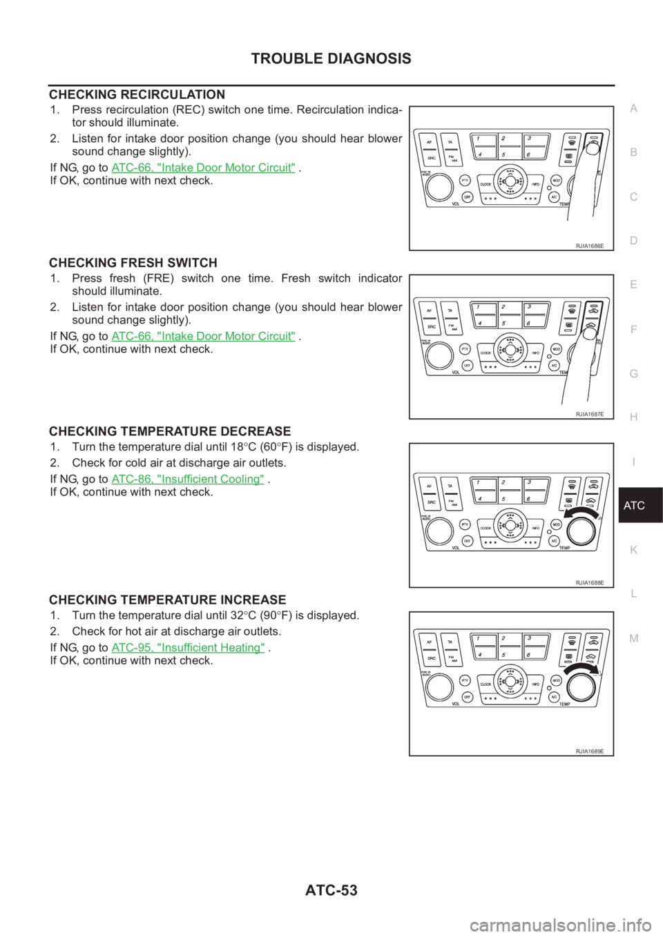
CHECKING RECIRCULATION
1. Press recirculation (REC) switch one time. Recirculation indica-
tor should illuminate.
2. Listen for intake door position change (you should hear blower
sound change slightly).
If NG, go to ATC-66, "
Intake Door Motor Circuit" .
If OK, continue with next check.
CHECKING FRESH SWITCH
1. Press fresh (FRE) switch one time. Fresh switch indicator
should illuminate.
2. Listen for intake door position change (you should hear blower
sound change slightly).
If NG, go to ATC-66, "
Intake Door Motor Circuit" .
If OK, continue with next check.
CHECKING TEMPERATURE DECREASE
1. Turn the temperature dial until 18°C (60°F) is displayed.
2. Check for cold air at discharge air outlets.
If NG, go to ATC-86, "
Insufficient Cooling" .
If OK, continue with next check.
CHECKING TEMPERATURE INCREASE
1. Turn the temperature dial until 32°C (90°F) is displayed.
2. Check for hot air at discharge air outlets.
If NG, go to ATC-95, "
Insufficient Heating" .
If OK, continue with next check.
RJIA1686E
RJIA1687E
RJIA1688E
RJIA1689E
Page 2035 of 3189

TROUBLE DIAGNOSIS
ATC-55
C
D
E
F
G
H
I
K
L
MA
B
AT C
Power Supply and Ground Circuit for Auto Amp.EJS001ZJ
SYMPTOM: A/C system does not come on.
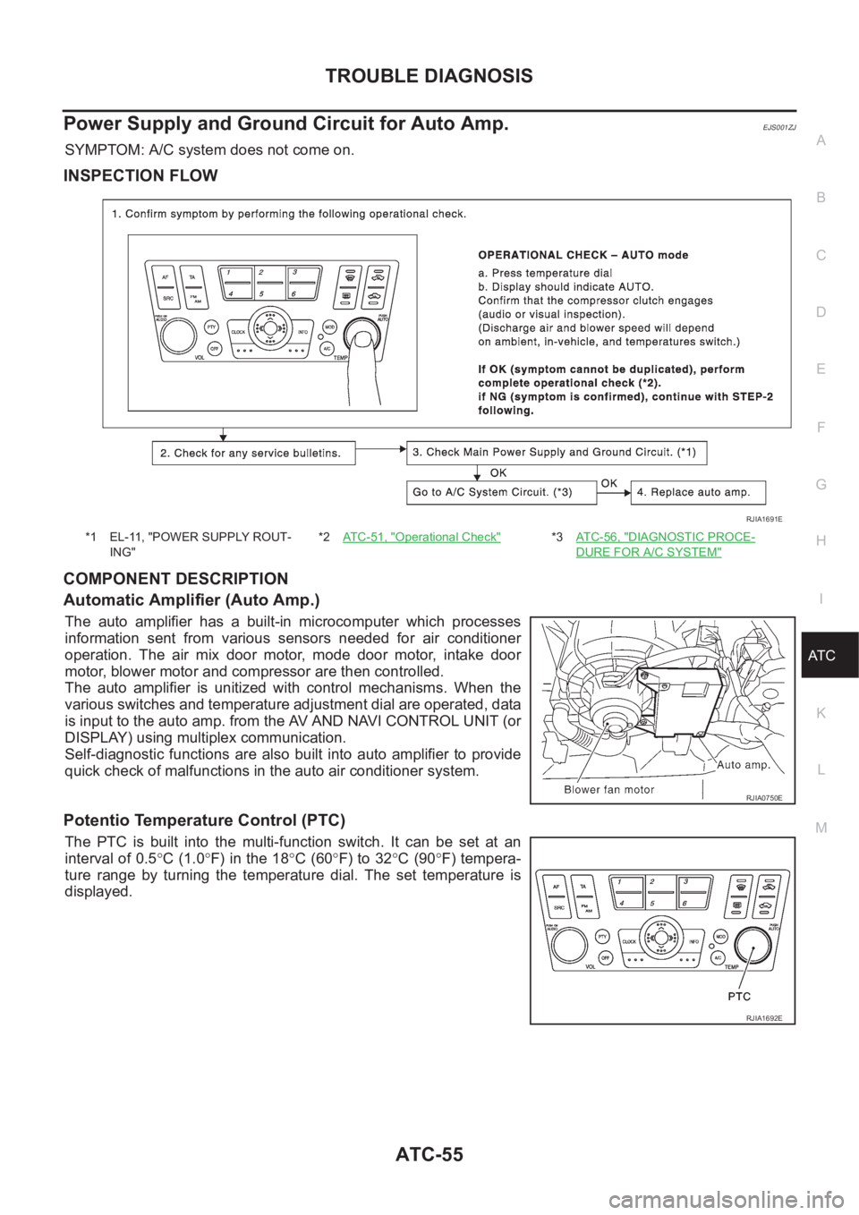
INSPECTION FLOW
COMPONENT DESCRIPTION
Automatic Amplifier (Auto Amp.)
The auto amplifier has a built-in microcomputer which processes
information sent from various sensors needed for air conditioner
operation. The air mix door motor, mode door motor, intake door
motor, blower motor and compressor are then controlled.
The auto amplifier is unitized with control mechanisms. When the
various switches and temperature adjustment dial are operated, data
is input to the auto amp. from the AV AND NAVI CONTROL UNIT (or
DISPLAY) using multiplex communication.
Self-diagnostic functions are also built into auto amplifier to provide
quick check of malfunctions in the auto air conditioner system.
Potentio Temperature Control (PTC)
The PTC is built into the multi-function switch. It can be set at an
interval of 0.5°C (1.0°F) in the 18°C (60°F) to 32°C (90°F) tempera-
ture range by turning the temperature dial. The set temperature is
displayed.
*1 EL-11, "POWER SUPPLY ROUT-
ING"*2AT C - 5 1 , "Operational Check"*3AT C - 5 6 , "DIAGNOSTIC PROCE-
DURE FOR A/C SYSTEM"
RJIA1691E
RJIA0750E
RJIA1692E
Page 2037 of 3189
TROUBLE DIAGNOSIS
ATC-57
C
D
E
F
G
H
I
K
L
MA
B
AT C
LAN System CircuitEJS001ZK
SYMPTOM: Mode door motor, intake door motor and/or air mix door motor does not operate normally.
DIAGNOSTIC PROCEDURE FOR LAN SYSTEM CIRCUIT
1.CHECK POWER SUPPLY FOR AUTO AMP. SIDE
OK or NG
OK >> GO TO 2.
NG >> Replace auto amp.
2.CHECK SIGNAL FOR AUTO AMP. SIDE
Confirm A/C LAN signal using an oscilloscope.
OK or NG
OK >> GO TO 3.
NG >> Replace auto amp.
RJIA1326E
Terminal
Vo lta g e (+)
(-)
Auto amp. connec-
torTe r m i n a l N o .
(Wire color)
M205 21 (G/Y) Ground Approx. 12V
RJIA0273E
Terminal
Vo l ta g e (+)
(-)
Auto amp. connectorTerminal No.
(Wire color)
M204 5 (R/Y) Ground
HAK0652D
Page 2038 of 3189
ATC-58
TROUBLE DIAGNOSIS
3. CHECK POWER SUPPLY FOR MOTOR SIDE
OK or NG
OK >> GO TO 4.
NG >> Replace harness or connector.
4. CHECK SIGNAL FOR MOTOR SIDE
Confirm A/C LAN signal using an oscilloscope.
OK or NG
OK >> GO TO 5.
NG >> Replace harness or connector.
5. CHECK MOTOR GROUND CIRCUIT
OK or NG
OK >> GO TO 6.
NG >> Replace harness or connector.
Door motorTerminal
Voltage (+)
(-)
ConnectorTerminal No.
(Wire color)
Mode M189 1 (G/Y)
GroundApprox.
12V Air mix M188 1 (G/Y)
Intake M104 1 (G/Y)
RJIA0509E
Door motorTerminal
Voltage (+)
(-)
ConnectorTerminal No.
(Wire color)
Mode M189 3 (R/Y)
Ground Air mix M188 3 (R/Y)
Intake M104 3 (R/Y)
HAK0652D
Door motorTerminal
Continuity (+)
(-)
ConnectorTerminal No.
(Wire color)
Mode M189 2 (B)
Ground Yes Air mix M188 2 (B)
Intake M104 2 (B)
RJIA0511E