Page 2099 of 3189

BLOWER UNIT
ATC-119
C
D
E
F
G
H
I
K
L
MA
B
AT C
BLOWER UNITPFP:27200
Removal and InstallationEJS00206
REMOVAL
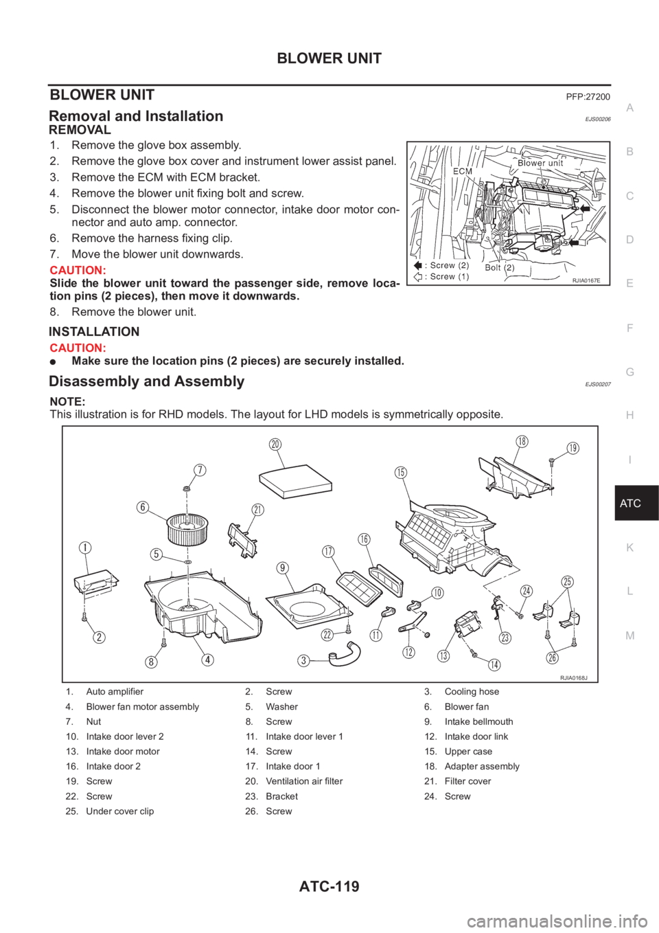
1. Remove the glove box assembly.
2. Remove the glove box cover and instrument lower assist panel.
3. Remove the ECM with ECM bracket.
4. Remove the blower unit fixing bolt and screw.
5. Disconnect the blower motor connector, intake door motor con-
nector and auto amp. connector.
6. Remove the harness fixing clip.
7. Move the blower unit downwards.
CAUTION:
Slide the blower unit toward the passenger side, remove loca-
tion pins (2 pieces), then move it downwards.
8. Remove the blower unit.
INSTALLATION
CAUTION:
●Make sure the location pins (2 pieces) are securely installed.
Disassembly and AssemblyEJS00207
NOTE:
This illustration is for RHD models. The layout for LHD models is symmetrically opposite.
RJIA0167E
1. Auto amplifier 2. Screw 3. Cooling hose
4. Blower fan motor assembly 5. Washer 6. Blower fan
7. Nut 8. Screw 9. Intake bellmouth
10. Intake door lever 2 11. Intake door lever 1 12. Intake door link
13. Intake door motor 14. Screw 15. Upper case
16. Intake door 2 17. Intake door 1 18. Adapter assembly
19. Screw 20. Ventilation air filter 21. Filter cover
22. Screw 23. Bracket 24. Screw
25. Under cover clip 26. Screw
RJIA0168J
Page 2101 of 3189
INTAKE DOOR MOTOR
ATC-121
C
D
E
F
G
H
I
K
L
MA
B
AT C
INTAKE DOOR MOTORPFP:27730
Removal and InstallationEJS00209
1. Remove the blower unit. Refer to AT C - 11 9 , "Removal and Instal-
lation"
2. Remove the intake door motor from the blower unit.
RJIA0822E
RJIA1721E
Page 2104 of 3189
ATC-124
HEATER & COOLING UNIT ASSEMBLY
16. Mode door link 2 17. Screw 18. Mode door lever 1
19. Fan control amp. 20. Screw 21. Mode door motor
22. Screw 23. Screw 24. Air mix door motor
25. Screw 26. Actuator bracket 27. Screw
28. Mode door link 29. Air mix door lever 30. Screw
31. Heater core 32. Evaporator 33. Expansion valve
34. Bolt 35. Cooler grommet 36. Instrument bracket
37. Drain hose 38. Lower case 39. Screw
Page 2105 of 3189
MODE DOOR MOTOR
ATC-125
C
D
E
F
G
H
I
K
L
MA
B
AT C
MODE DOOR MOTORPFP:27731
Removal and InstallationEJS0020C
1. Disconnect the mode door motor connector.
2. Remove the mode door motor.
RJIA0826E
RJIA1725E
Page 2106 of 3189
ATC-126
AIR MIX DOOR MOTOR
AIR MIX DOOR MOTOR
PFP:27732
Removal and InstallationEJS0020D
1. Disconnect the air mix door motor connector.
2. Remove the air mix door motor.
RJIA0828E
RJIA0829E
Page 2589 of 3189

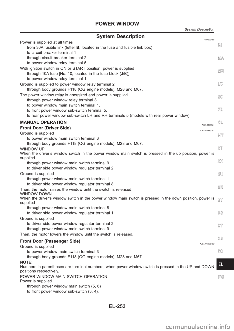
System Description=NJEL0498Power is supplied at all times
from 30A fusible link (letterB, located in the fuse and fusible link box)
to circuit breaker terminal 1
through circuit breaker terminal 2
to power window relay terminal 5
With ignition switch in ON or START position, power is supplied
through 10A fuse [No. 10, located in the fuse block (J/B)]
to power window relay terminal 1
Ground is supplied to power window relay terminal 2
through body grounds F118 (QG engine models), M28 and M67.
The power window relay is energized and power is supplied
through power window relay terminal 3
to power window main switch terminal 1,
to front power window sub-switch terminal 5,
to rear power window sub-switch LH and RH terminals 5 (models with rear power window).
MANUAL OPERATIONNJEL0498S01Front Door (Driver Side)NJEL0498S0101Ground is supplied
to power window main switch terminal 3
through body grounds F118 (QG engine models), M28 and M67.
WINDOW UP
When the driver’s window switch in the power window main switch is pressed in the up position, power is
supplied
through power window main switch terminal 9
to driver side power window regulator terminal 2.
Ground is supplied
through power window main switch terminal 1
to driver side power window regulator terminal 8.
Then, the motor raises the window until the switch is released.
WINDOW DOWN
When the driver’s window switch in the power window main switch is pressed in the down position, power is
supplied
through power window main switch terminal 8
to driver side power window regulator terminal 1.
Ground is supplied
to driver side power window regulator terminal 2
through power window main switch terminal 9.
Then, the motor lowers the window until the switch is released.
Front Door (Passenger Side)NJEL0498S0102Ground is supplied
to power window main switch terminal 3
through body grounds F118 (QG engine models), M28 and M67.
NOTE:
Numbers in parentheses are terminal numbers, when power window switch is pressed in the UP and DOWN
positions respectively.
POWER WINDOW MAIN SWITCH OPERATION
Power is supplied
through power window main switch (5, 6)
to front power window sub-switch (3, 4).
GI
MA
EM
LC
EC
FE
CL
MT
AT
AX
SU
BR
ST
RS
BT
HA
SC
IDX
POWER WINDOW
System Description
EL-253
Page 2590 of 3189

The subsequent operation is the same as the front power window sub-switch operation.
FRONT POWER WINDOW SUB-SWITCH OPERATION
Power is supplied
through front power window sub-switch (1, 2)
to front passenger side power window regulator (1, 2).
Ground is supplied
to front passenger side power window regulator (2, 1)
through front power window sub-switch (2, 1)
to front power window sub-switch (4, 3)
through power window main switch (6, 5).
Then, the motor raises or lowers the window until the switch is released.
Rear DoorNJEL0498S0103Rear door windows will raise and lower in the same manner as passenger’s door window.
POWER WINDOW LOCKNJEL0498S02The power window lock is designed to lock operation of all windows except for driver’s door window.
When the lock switch is pressed to lock position, ground of the sub-switches in the power window main switch
is disconnected. This prevents the power window motors from operating.
AUTO OPERATIONNJEL0498S03The power window AUTO feature enables the driver to open the driver’s window without holding the window
switch in the down position.
The AUTO feature operates on the driver’s window.
POWER WINDOW
System Description (Cont’d)
EL-254
Page 2714 of 3189

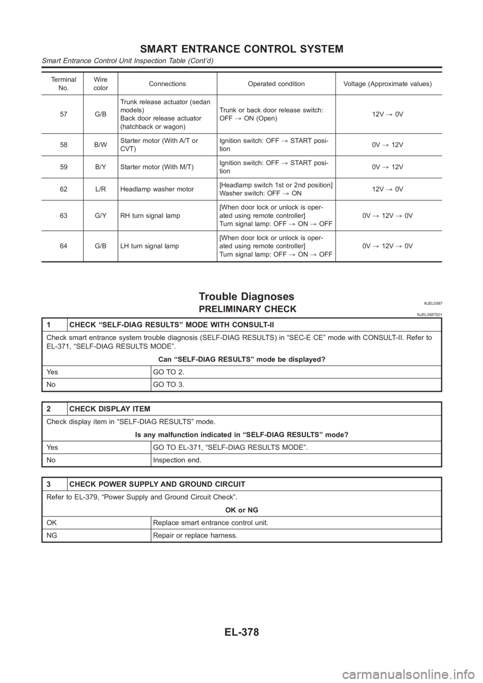
Terminal
No.Wire
colorConnections Operated condition Voltage (Approximate values)
57 G/BTrunk release actuator (sedan
models)
Back door release actuator
(hatchback or wagon)Trunk or back door release switch:
OFF,ON (Open)12V,0V
58 B/WStarter motor (With A/T or
CVT)Ignition switch: OFF,START posi-
tion0V,12V
59 B/Y Starter motor (With M/T)Ignition switch: OFF,START posi-
tion0V,12V
62 L/R Headlamp washer motor[Headlamp switch 1st or 2nd position]
Washer switch: OFF,ON12V,0V
63 G/Y RH turn signal lamp[When door lock or unlock is oper-
ated using remote controller]
Turn signal lamp: OFF,ON,OFF0V,12V,0V
64 G/B LH turn signal lamp[When door lock or unlock is oper-
ated using remote controller]
Turn signal lamp: OFF,ON,OFF0V,12V,0V
Trouble DiagnosesNJEL0587PRELIMINARY CHECKNJEL0587S01
1 CHECK “SELF-DIAG RESULTS” MODE WITH CONSULT-II
Check smart entrance system trouble diagnosis (SELF-DIAG RESULTS) in “SEC-E CE” mode with CONSULT-II. Refer to
EL-371, “SELF-DIAG RESULTS MODE”.
Can “SELF-DIAG RESULTS” mode be displayed?
Ye s G O T O 2 .
No GO TO 3.
2 CHECK DISPLAY ITEM
Check display item in “SELF-DIAG RESULTS” mode.
Is any malfunction indicated in “SELF-DIAG RESULTS” mode?
Yes GO TO EL-371, “SELF-DIAG RESULTS MODE”.
No Inspection end.
3 CHECK POWER SUPPLY AND GROUND CIRCUIT
Refer to EL-379, “Power Supply and Ground Circuit Check”.
OK or NG
OK Replace smart entrance control unit.
NG Repair or replace harness.
SMART ENTRANCE CONTROL SYSTEM
Smart Entrance Control Unit Inspection Table (Cont’d)
EL-378