2003 NISSAN ALMERA N16 door motor
[x] Cancel search: door motorPage 2937 of 3189
HEATER &
MANUAL AIR CONDITIONER
SECTION
HA
CONTENTS
MANUAL
PRECAUTIONS<0011001100110011001100110011001100110011001100110011001100110011001100110011001100110011001100110011001100110011001100110011001100110011001100110011001100110011001100110011001100110011001100110011001100
11001100110011001100110011001100110011001100110011[2
Supplemental Restraint System (SRS)″AIR
BAG″and″SEAT BELT PRE-TENSIONER″...............2
Precautions for Working with HFC-134a (R-134a) .....2
General Refrigerant Precautions .................................2
Precautions for Refrigerant Connection ......................3
Precautions for Servicing Compressor ........................5
Precautions for Service Equipment .............................6
Wiring Diagrams and Trouble Diagnosis .....................8
PREPARATION<0011001100110011001100110011001100110011001100110011001100110011001100110011001100110011001100110011001100110011001100110011001100110011001100110011001100110011001100110011001100110011001100110011001100
11001100110011001100110011001100110011001100110011[9
Special Service Tools ..................................................9
HFC-134a (R-134a) Service Tools and
Equipment <0011001100110011001100110011001100110011001100110011001100110011001100110011001100110011001100110011001100110011001100110011001100110011001100110011001100110011001100110011001100110011001100110011001100
11001100110011[............10
DESCRIPTION<0011001100110011001100110011001100110011001100110011001100110011001100110011001100110011001100110011001100110011001100110011001100110011001100110011001100110011001100110011001100110011001100110011001100
11001100110011001100110011001100110011001100110011[12
Refrigeration System .................................................12
CSV613 Variable Displacement Compressor............13
Component Layout ....................................................17
Control Operation ......................................................18
Discharge Air Flow.....................................................19
System Description ....................................................20
TROUBLE DIAGNOSES................................................21
Component Location..................................................21
Wiring Diagram - Heater............................................23
Circuit Diagram - Air Conditioner...............................24
Wiring Diagram - A/C, M - .........................................25
How to Perform Trouble Diagnoses for Quick
and Accurate Repair ..................................................34Operational Check .....................................................35
Intake Door <0011001100110011001100110011001100110011001100110011001100110011001100110011001100110011001100110011001100110011001100110011001100110011001100110011001100110011001100110011001100110011001100110011001100
1100110011[...........37
Mode Door <0011001100110011001100110011001100110011001100110011001100110011001100110011001100110011001100110011001100110011001100110011001100110011001100110011001100110011001100110011001100110011001100110011001100
110011001100110011[..........41
Air Mix Door <0011001100110011001100110011001100110011001100110011001100110011001100110011001100110011001100110011001100110011001100110011001100110011001100110011001100110011001100110011001100110011001100110011001100
1100110011[..........43
Blower Motor<0011001100110011001100110011001100110011001100110011001100110011001100110011001100110011001100110011001100110011001100110011001100110011001100110011001100110011001100110011001100110011001100110011001100
110011[..........45
Magnet Clutch<0011001100110011001100110011001100110011001100110011001100110011001100110011001100110011001100110011001100110011001100110011001100110011001100110011001100110011001100110011001100110011001100110011001100
11[.........52
Insufficient Cooling ....................................................66
Insufficient Heating ....................................................75
Noise <0011001100110011001100110011001100110011001100110011001100110011001100110011001100110011001100110011001100110011001100110011001100110011001100110011001100110011001100110011001100110011001100110011001100
110011001100110011001100110011[................76
SERVICE PROCEDURE................................................77
HFC-134a (R-134a) Service Procedure ....................77
Maintenance of Lubricant Quantity in
Compressor <0011001100110011001100110011001100110011001100110011001100110011001100110011001100110011001100110011001100110011001100110011001100110011001100110011001100110011001100110011001100110011001100110011001100
1100110011[..........79
Compressor <0011001100110011001100110011001100110011001100110011001100110011001100110011001100110011001100110011001100110011001100110011001100110011001100110011001100110011001100110011001100110011001100110011001100
1100110011[..........82
Compressor Clutch - CSV613 (CALSONIC
make) <0011001100110011001100110011001100110011001100110011001100110011001100110011001100110011001100110011001100110011001100110011001100110011001100110011001100110011001100110011001100110011001100110011001100
110011001100110011001100110011[...............83
Heater & Cooling Unit (Heater Core) ........................87
A/C Evaporator ..........................................................87
Blower Unit <0011001100110011001100110011001100110011001100110011001100110011001100110011001100110011001100110011001100110011001100110011001100110011001100110011001100110011001100110011001100110011001100110011001100
1100110011[...........89
Refrigerant Lines .......................................................90
Belt <0011001100110011001100110011001100110011001100110011001100110011001100110011001100110011001100110011001100110011001100110011001100110011001100110011001100110011001100110011001100110011001100110011001100
1100110011001100110011001100110011[..................94
Ventilation Air Filter ....................................................95
SERVICE DATA AND SPECIFICATIONS (SDS).........96
Compressor <0011001100110011001100110011001100110011001100110011001100110011001100110011001100110011001100110011001100110011001100110011001100110011001100110011001100110011001100110011001100110011001100110011001100
1100110011[..........96
Lubricant <0011001100110011001100110011001100110011001100110011001100110011001100110011001100110011001100110011001100110011001100110011001100110011001100110011001100110011001100110011001100110011001100110011001100
11001100110011[..............96
Refrigerant <0011001100110011001100110011001100110011001100110011001100110011001100110011001100110011001100110011001100110011001100110011001100110011001100110011001100110011001100110011001100110011001100110011001100
110011[.............96
Engine Idling Speed (When A/C is On).....................96
Belt Tension <0011001100110011001100110011001100110011001100110011001100110011001100110011001100110011001100110011001100110011001100110011001100110011001100110011001100110011001100110011001100110011001100110011001100
110011[...........96
GI
MA
EM
LC
EC
FE
CL
MT
AT
AX
SU
BR
ST
RS
BT
SC
EL
IDX
Page 2970 of 3189
How to Perform Trouble Diagnoses for Quick
and Accurate Repair
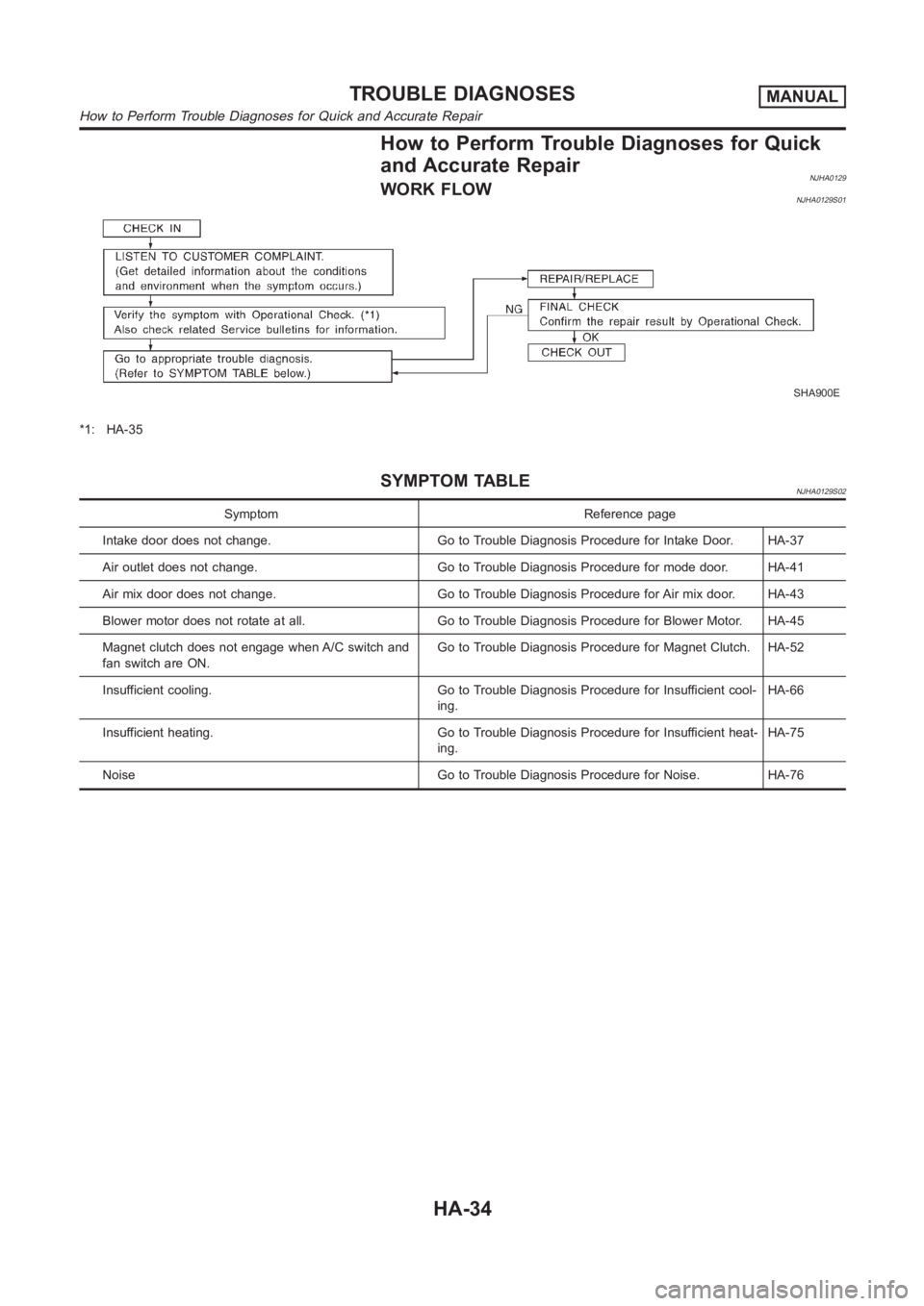
NJHA0129WORK FLOWNJHA0129S01
SHA900E
*1: HA-35
SYMPTOM TABLENJHA0129S02
Symptom Reference page
Intake door does not change. Go to Trouble Diagnosis Procedure for Intake Door. HA-37
Air outlet does not change. Go to Trouble Diagnosis Procedure for mode door. HA-41
Air mix door does not change. Go to Trouble Diagnosis Procedure for Air mix door. HA-43
Blower motor does not rotate at all. Go to Trouble Diagnosis Procedure for Blower Motor. HA-45
Magnet clutch does not engage when A/C switch and
fan switch are ON.Go to Trouble Diagnosis Procedure for Magnet Clutch. HA-52
Insufficient cooling. Go to Trouble Diagnosis Procedure for Insufficient cool-
ing.HA-66
Insufficient heating. Go to Trouble Diagnosis Procedure for Insufficientheat-
ing.HA-75
Noise Go to Trouble Diagnosis Procedure for Noise. HA-76
TROUBLE DIAGNOSESMANUAL
How to Perform Trouble Diagnoses for Quick and Accurate Repair
HA-34
Page 2971 of 3189
Operational Check=NJHA0130The purpose of the operational check is to confirm that the system
operates properly.
CONDITIONS:NJHA0130S01Engine running and at usual operating temperature.
NHA374
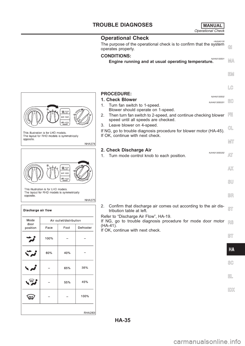
PROCEDURE:NJHA0130S021. Check BlowerNJHA0130S02011. Turn fan switch to 1-speed.
Blower should operate on 1-speed.
2. Then turn fan switch to 2-speed, and continue checking blower
speed until all speeds are checked.
3. Leave blower on 4-speed.
If NG, go to trouble diagnosis procedure for blower motor (HA-45).
If OK, continue with next check.
NHA375
2. Check Discharge AirNJHA0130S02021. Turn mode control knob to each position.
RHA280I
2. Confirm that discharge air comes out according to the air dis-
tribution table at left.
Refer to “Discharge Air Flow”, HA-19.
If NG, go to trouble diagnosis procedure for mode door motor
(HA-41).
If OK, continue with next check.
GI
MA
EM
LC
EC
FE
CL
MT
AT
AX
SU
BR
ST
RS
BT
SC
EL
IDX
TROUBLE DIAGNOSESMANUAL
Operational Check
HA-35
Page 2974 of 3189
RHA623H
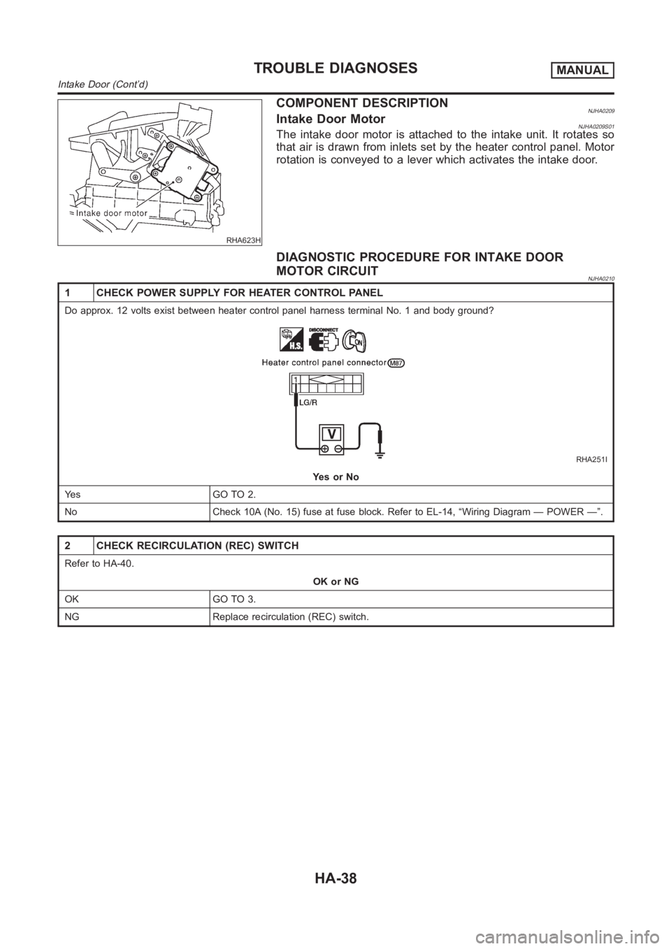
COMPONENT DESCRIPTIONNJHA0209Intake Door MotorNJHA0209S01The intake door motor is attached to the intake unit. It rotates so
that air is drawn from inlets set by the heater control panel. Motor
rotation is conveyed to a lever which activates the intake door.
DIAGNOSTIC PROCEDURE FOR INTAKE DOOR
MOTOR CIRCUIT
NJHA0210
1 CHECK POWER SUPPLY FOR HEATER CONTROL PANEL
Do approx. 12 volts exist between heater control panel harness terminal No. 1 and body ground?
RHA251I
YesorNo
Ye s G O T O 2 .
No Check 10A (No. 15) fuse at fuse block. Refer to EL-14, “Wiring Diagram — POWER —”.
2 CHECK RECIRCULATION (REC) SWITCH
Refer to HA-40.
OK or NG
OK GO TO 3.
NG Replace recirculation (REC) switch.
TROUBLE DIAGNOSESMANUAL
Intake Door (Cont’d)
HA-38
Page 2975 of 3189
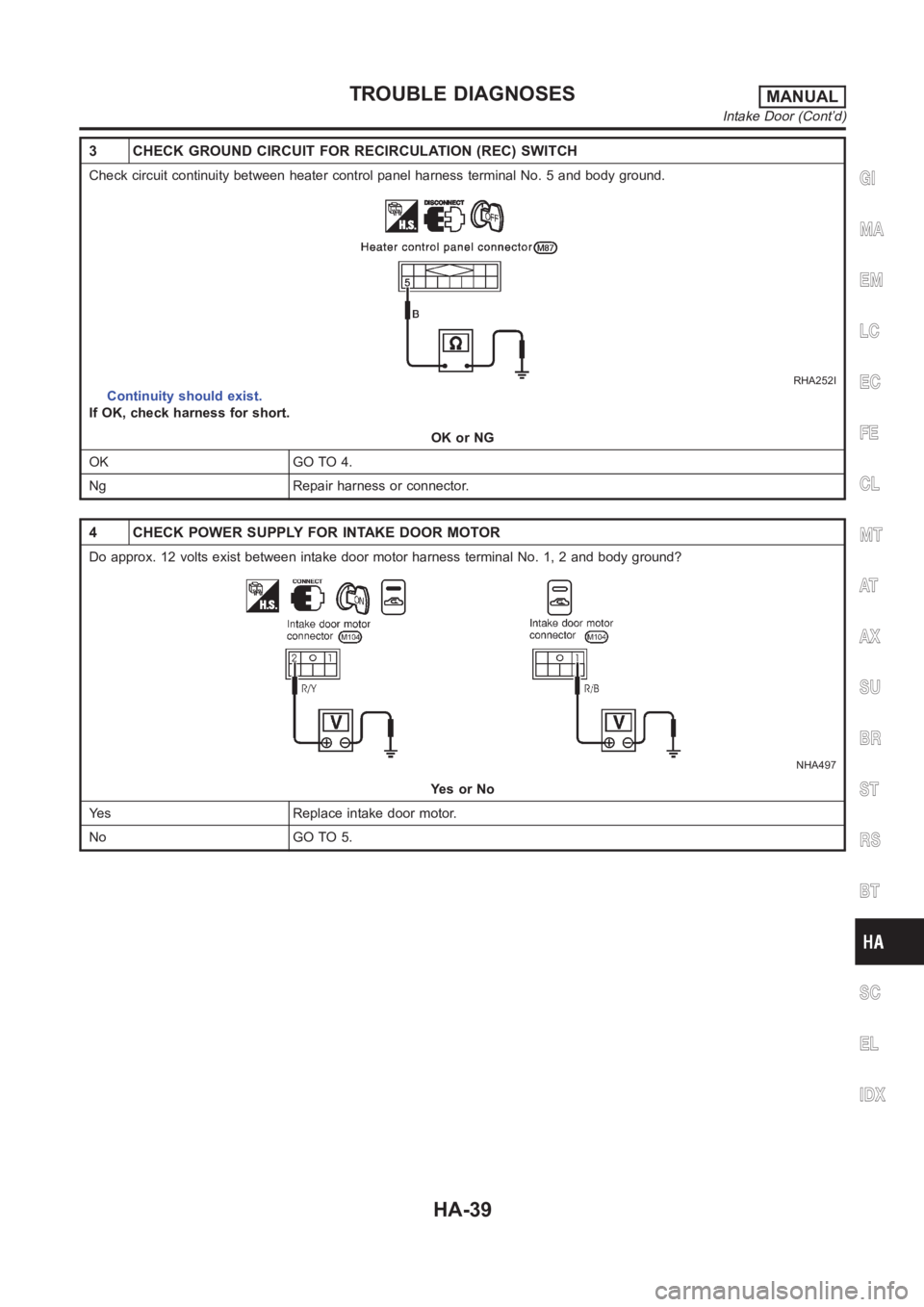
3 CHECK GROUND CIRCUIT FOR RECIRCULATION (REC) SWITCH
Check circuit continuity between heater control panel harness terminal No. 5 and body ground.
RHA252I
Continuity should exist.
If OK, check harness for short.
OK or NG
OK GO TO 4.
Ng Repair harness or connector.
4 CHECK POWER SUPPLY FOR INTAKE DOOR MOTOR
Do approx. 12 volts exist between intake door motor harness terminal No. 1,2 and body ground?
NHA497
YesorNo
Yes Replace intake door motor.
No GO TO 5.
GI
MA
EM
LC
EC
FE
CL
MT
AT
AX
SU
BR
ST
RS
BT
SC
EL
IDX
TROUBLE DIAGNOSESMANUAL
Intake Door (Cont’d)
HA-39
Page 2976 of 3189
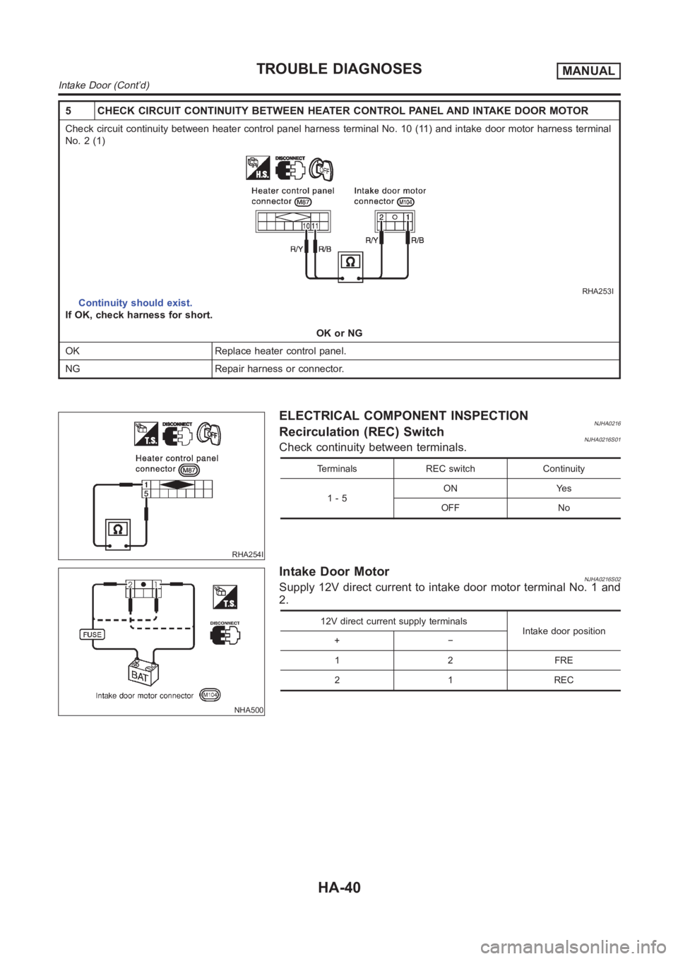
5 CHECK CIRCUIT CONTINUITY BETWEEN HEATER CONTROL PANEL AND INTAKE DOOR MOTOR
Check circuit continuity between heater control panel harness terminal No. 10 (11) and intake door motor harness terminal
No. 2 (1)
RHA253I
Continuity should exist.
If OK, check harness for short.
OK or NG
OK Replace heater control panel.
NG Repair harness or connector.
RHA254I
ELECTRICAL COMPONENT INSPECTIONNJHA0216Recirculation (REC) SwitchNJHA0216S01Check continuity between terminals.
Terminals REC switch Continuity
1-5ON Yes
OFF No
NHA500
Intake Door MotorNJHA0216S02Supply 12V direct current to intake door motor terminal No. 1 and
2.
12V direct current supply terminals
Intake door position
+−
12FRE
21REC
TROUBLE DIAGNOSESMANUAL
Intake Door (Cont’d)
HA-40
Page 3176 of 3189
A
A/C air flow (manual A/C) ..............................HA-19
A/C air flow <0011001100110011001100110011001100110011001100110011001100110011001100110011001100110011001100110011001100110011001100110011001100110011001100110011001100110011001100110011001100110011001100110011001100
110024>�TC-27
A/C component layout (manual A/C) .............HA-17
A/C compressor clutch removal and
installation (manual A/C).............................HA-82
A/C compressor clutch removal and
installation ...............................................ATC-139
A/C compressor precaution (manual
A/C) <0011001100110011001100110011001100110011001100110011001100110011001100110011001100110011001100110011001100110011001100110011001100110011001100110011001100110011001100110011001100110011001100110011001100
1100110011001100110011001100110011[....HA-5
A/C compressor precaution ............................ATC-7
A/C compressor special service tool
(manual A/C) .................................................HA-9
A/C compressor special service tool ............ATC-11
A/C control linkage adjustment (manual
A/C) <0011001100110011001100110011001100110011001100110011001100110011001100110011001100110011001100110011001100110011001100110011001100110011001100110011001100110011001100110011001100110011001100110011001100
1100110011001100110011001100110011[..HA-42
A/C control operation (manual A/C) ...............HA-18
A/C diagnostic work flow (manual A/C)..........HA-34
A/C evaporator (manual A/C) .........................HA-87
A/C HFC134a (R134a) system precau-
tion (manual A/C) ..........................................HA-2
A/C HFC134a (R134a) system
precaution <0011001100110011001100110011001100110011001100110011001100110011001100110011001100110011001100110011001100110011001100110011001100110011001100110011001100110011001100110011001100110011001100110011001100
110024>�TC-4
A/C HFC134a (R134a) system service
procedure (manual A/C) .............................HA-77
A/C HFC134a (R134a) system service
procedure ................................................ATC-133
A/C HFC134a (R134a) system service
tools (manual A/C) ......................................HA-10
A/C HFC134a (R134a) system service
tools<0011001100110011001100110011001100110011001100110011001100110011001100110011001100110011001100110011001100110011001100110011001100110011001100110011001100110011001100110011001100110011001100110011001100
110011001100110011001100110011[.ATC-11
A/C HFC134a system service equip-
ment precaution (manual A/C)......................HA-6
A/C HFC134a system service equip-
ment precaution ..........................................ATC-7
A/C lubricant (R134a) (manual A/C) ..............HA-79
A/C lubricant (R134a) ...................................ATC-20
A/C lubrication oil .......................................ATC-150
A/C operational check (manual A/C)..............HA-35
A/C operational check ..................................ATC-51
A/C performance chart (manual A/C).............HA-69
A/C performance test diagnoses
(manual A/C) ...............................................HA-67
A/C performance test diagnoses ..................ATC-89
A/C relay (manual A/C) ..................................HA-65
A/C reray <0011001100110011001100110011001100110011001100110011001100110011001100110011001100110011001100110011001100110011001100110011001100110011001100110011001100110011001100110011001100110011001100110011001100
110011001100110024[TC-85
A/C self-diagnoses (auto A/C) ......................ATC-42
A/C service data specification (manual
A/C) <0011001100110011001100110011001100110011001100110011001100110011001100110011001100110011001100110011001100110011001100110011001100110011001100110011001100110011001100110011001100110011001100110011001100
1100110011001100110011001100110011[..HA-96
A/C service data specification ....................ATC-150
A/C switch (manual A/C) ................................HA-65
A/C system description (auto A/C) ...............ATC-22
A/C trouble diagnoses (auto A/C) ................ATC-29
A/C, A - Wiring diagram................................ATC-33
A/C, M - Wiring diagram (manual A/C) ..........HA-25
A/CCUT - Wiring diagram (YD engine) ........EC-212
A/T - Wiring diagram - AT - FTS ...................AT-120
A/T - Wiring diagram - AT - MAIN .................AT-341A/T - Wiring diagram - AT - PNP/SW ............AT-114
A/T - Wiring diagram - AT -
VSS A/T........................................AT-127, AT-346
A/T fluid checking ............................................AT-13
A/T fluid replacement ......................................AT-13
A/T fluid temperature sensor.........................AT-123
A/T shift lock system - Wiring diagram .........AT-400
A/T shift lock system .....................................AT-399
A/T trouble diagnoses ........................AT-56, AT-256
A/T Wiring diagram - AT -
ENG SS........................................AT-131, AT-386
A/T Wiring diagram AT - 1ST ........................AT-137
A/T Wiring diagram AT - 2ND .......................AT-143
A/T Wiring diagram AT - 3RD .......................AT-149
A/T Wiring diagram AT - 4TH ........................AT-155
A/T Wiring diagram AT - BA/FTS.....AT-198, AT-380
A/T Wiring diagram AT - LPSV ........AT-167, AT-391
A/T Wiring diagram AT - OVRCSV ..AT-190, AT-370
A/T Wiring diagram AT - SSV/A.......AT-174, AT-360
A/T Wiring diagram AT - SSV/B.......AT-179, AT-365
A/T Wiring diagram AT - TCV ..........AT-162, AT-375
A/T Wiring diagram AT - TPS ..........AT-185, AT-355
A/T Wiring diagrawm AT -
VSSMTR ......................................AT-204, AT-351
ABS (anti-lock brake system).........................BR-45
ABS - Wiring diagram ....................................BR-50
ABS sensor rotor ............................................AX-24
Accelerator control system .........................FE-3, 14
Accelerator pedal position (APP) sen-
sor (QG engine) ..........EC-212, EC-219, EC-346,
EC-538, EC-545, EC-619
Accelerator pedal released position
learning (QG engine)....................EC-31, EC-426
Accelerator position sensor
(YD engine).................................................EC-89
Air bag disposal..............................................RS-35
Air bag precautions ...........................................GI-3
Air bag <0011001100110011001100110011001100110011001100110011001100110011001100110011001100110011001100110011001100110011001100110011001100110011001100110011001100110011001100110011001100110011001100110011001100
11001100110011001100110011[...RS-20
Air bleeding (hydraulic clutch) ........................CL-10
Air bleeding for brake system ..........................BR-8
Air cleaner and air duct (QG engine) ............EM-14
Air cleaner filter (QG engine).........................EM-14
Air conditioner cut control
(QG engine)..................................EC-26, EC-421
Air conditioner cut control (YD engine) ..........EC-19
Air flow meter - See Mass air flow sen-
sor (QG engine) .........................EC-135, EC-497
Air flow meter - See Mass air flow sen-
sor (YD engine) ..........................................EC-78
Air mix door control linkage adjustment
(manual A/C) ...............................................HA-44
Air mix door control linkage
adjustment ................................ATC-65, ATC-127
Air mix. door motor.......................ATC-63, ATC-127
Air spoiler, rear................................................BT-47
Alternator <0011001100110011001100110011001100110011001100110011001100110011001100110011001100110011001100110011001100110011001100110011001100110011001100110011001100110011001100110011001100110011001100110011001100
1100110011[...SC-30
Ambient sensor...........ATC-101, ATC-103, ATC-116
Angular tightening application
(QG engine)..................................................EM-3
Angular tightening application
(YD engine) ..................................................EM-3
ALPHABETICAL INDEX
IDX-2
Page 3178 of 3189
COOL/F - Wiring diagram
(QG engine)................................EC-328, EC-601
COOL/F - Wiring diagram (YD engine) ........EC-130
Coolant mixture ratio......................................MA-21
Cooling circuit (engine).............................LC-12, 36
Cooling fan control (YD engine)...................EC-130
Cooling fan control system .......................LC-17, 42
Cooling fan motor (QG engine) .....EC-335, EC-608
Coupling sleeve (M/T)........................MT-31, 55, 93
Crankcase emission control system -
See positive crankcase ventilation
(YD engine).................................................EC-19
Crankcase ventilation system - See
Positive crankcase ventilation
(QG engine)................................EC-403, EC-722
Crankcase ventilation system - See
Positive crankcase ventilation
(YD engine).................................................EC-19
Crankshaft (QG engine).................................EM-71
Crankshaft (YD engine) .................................EM-75
Crankshaft position sensor (POS)
(QG engine)................................EC-235, EC-556
Crankshaft position sensor (TDC)
(YD engine).................................................EC-99
Cylinder block (QG engine) ...........................EM-70
Cylinder block (YD engine) ............................EM-66
Cylinder block boring (QG engine) ................EM-88
Cylinder block boring(QR) .............................EM-89
Cylinder head (QG engine)............................EM-57
Cylinder head (YD engine) ............................EM-45
Cylinder head bolt tightening
(QG engine)................................................EM-59
D
Data link connector
(QG engine) ...EC-398, EC-399, EC-717, EC-718
Data link connector for Consult
(QG engine)..................................EC-90, EC-468
Data link connector for Consult
(YD engine).................................................EC-39
Daytime light system.......................................EL-46
DEF - Wiring diagram ...................................EL-176
Diagnosis sensor unit .....................................RS-26
Diagnostic trouble code (DTC) for OBD
system (QG engine) ......................EC-10, EC-39,
EC-407, EC-430
Diagnostic trouble code (DTC) for OBD
system (YD engine) ................................EC-4, 34
Diagnostic trouble code (DTC) inspec-
tion priority chart (QG engine) .....EC-62, EC-441
Differential gear (FF M/T) ....MT-31, 43, 55, 93, 107
Dimensions <0011001100110011001100110011001100110011001100110011001100110011001100110011001100110011001100110011001100110011001100110011001100110011001100110011001100110011001100110011001100110011001100110011001100
1100110011[.GI-44
Dome light - See Interior lamp .......................EL-80
Door glass <0011001100110011001100110011001100110011001100110011001100110011001100110011001100110011001100110011001100110011001100110011001100110011001100110011001100110011001100110011001100110011001100110011001100
11001100110011[.BT-17
Door lock <0011001100110011001100110011001100110011001100110011001100110011001100110011001100110011001100110011001100110011001100110011001100110011001100110011001100110011001100110011001100110011001100110011001100
110011001100110011[..BT-21
Door mirror <0011001100110011001100110011001100110011001100110011001100110011001100110011001100110011001100110011001100110011001100110011001100110011001100110011001100110011001100110011001100110011001100110011001100
1100110011[.BT-72
Door trim <0011001100110011001100110011001100110011001100110011001100110011001100110011001100110011001100110011001100110011001100110011001100110011001100110011001100110011001100110011001100110011001100110011001100
110011001100110011[..BT-39
Door, front <0011001100110011001100110011001100110011001100110011001100110011001100110011001100110011001100110011001100110011001100110011001100110011001100110011001100110011001100110011001100110011001100110011001100
1100110011[..BT-16
Door, rear <0011001100110011001100110011001100110011001100110011001100110011001100110011001100110011001100110011001100110011001100110011001100110011001100110011001100110011001100110011001100110011001100110011001100
11001100110011[..BT-16Drive belt (QG engine) ...................................EM-11
Drive shaft (front)............................................AX-10
Dropping resistor (A/T) ....................AT-171, AT-395
DTC work support (QG engine) .....................EC-97
Dual pressure switch (manual A/C) ...............HA-12
Dual pressure switch ......ATC-15, ATC-86, ATC-144
Duct and grilles...........................................ATC-131
E
ECCS-D control module
(YD engine) ........EC-66, 116, 175, 177, 181, 183
ECM input/output signal
(QG engine)..................................EC-81, EC-460
ECM input/output signal (YD engine) ............EC-66
ECM power supply
(QG engine) ...EC-111, EC-269, EC-488, EC-573
ECM/PW - Wiring diagram
(QG engine)................................EC-270, EC-574
ECTS - Wiring diagram
(QG engine)................................EC-147, EC-505
ECTS - Wiring diagram (YD engine)..............EC-84
EGR volume control valve (YD engine) .......EC-197
EGRC1 - Wiring diagram (YD engine) .........EC-199
Electric sun roof ............................................EL-249
Electric throttle control actuator
(QG engine) ................EC-277, EC-279, EC-292,
EC-577, EC-580, EC-593
Electrical diagnoses.........................................GI-22
Electrical load signal circuit
(QG engine)................................EC-393, EC-712
Electrical unit ................................................Foldout
Electrical units location .................................EL-543
Electronic fuel injection pump
(YD engine) ...............EC-25, 118, 124, 145, 151,
157, 163, 169, 185
Electronic ignition (EI) system
(QG engine)..................................EC-25, EC-420
Engine compartment .......................................BT-75
Engine control circuit diagram
(QG engine)..................................EC-79, EC-458
Engine control circuit diagram
(YD engine).................................................EC-14
Engine control component parts loca-
tion (QG engine)...........................EC-75, EC-454
Engine control component parts loca-
tion (YD engine) ..........................................EC-11
Engine control module (ECM)
(QG engine)................................EC-266, EC-570
Engine control module (ECM)
(YD engine) ........EC-66, 116, 175, 177, 181, 183
Engine control system diagram and
chart (QG engine) ........................EC-21, EC-416
Engine control system diagram and
chart (YD engine) .......................................EC-15
Engine coolant temperature sensor
(ECTS) (QG engine) ..................EC-145, EC-503
Engine coolant temperature sensor
(ECTS) (YD engine) ...................................EC-84
ALPHABETICAL INDEX
IDX-4