2003 NISSAN ALMERA N16 radio wire
[x] Cancel search: radio wirePage 2253 of 3189

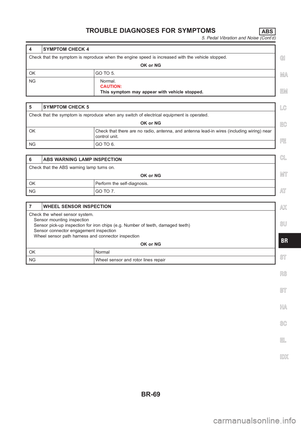
4 SYMPTOM CHECK 4
Check that the symptom is reproduce when the engine speed is increased withthe vehicle stopped.
OK or NG
OK GO TO 5.
NG Normal.
CAUTION:
This symptom may appear with vehicle stopped.
5 SYMPTOM CHECK 5
Check that the symptom is reproduce when any switch of electrical equipment is operated.
OK or NG
OK Check that there are no radio, antenna, and antenna lead-in wires (including wiring) near
control unit.
NG GO TO 6.
6 ABS WARNING LAMP INSPECTION
Check that the ABS warning lamp turns on.
OK or NG
OK Perform the self-diagnosis.
NG GO TO 7.
7 WHEEL SENSOR INSPECTION
Check the wheel sensor system.
Sensor mounting inspection
Sensor pick-up inspection for iron chips (e.g. Number of teeth, damaged teeth)
Sensor connector engagement inspection
Wheel sensor path harness and connector inspection
OK or NG
OK Normal
NG Wheel sensor and rotor lines repair
GI
MA
EM
LC
EC
FE
CL
MT
AT
AX
SU
ST
RS
BT
HA
SC
EL
IDX
TROUBLE DIAGNOSES FOR SYMPTOMSABS
5. Pedal Vibration and Noise (Cont’d)
BR-69
Page 2339 of 3189

Trouble Diagnoses/YD Engine Models with
Common Rail and K9K Engine Models...................292
POWER DOOR LOCK - SUPER LOCK -...................301
System Description ..................................................301
Schematic <0011001100110011001100110011001100110011001100110011001100110011001100110011001100110011001100110011001100110011001100110011001100110011001100110011001100110011001100110011001100110011001100110011001100
11001100110011[..........304
Wiring Diagram - S/LOCK - .....................................306
Trouble Diagnosis/QG and YD Engine Models
with Common Rail ...................................................313
Trouble Diagnoses/YD Engine Models without
Common Rail and K9K Engine Models...................339
MULTI-REMOTE CONTROL SYSTEM.......................352
System Description ..................................................352
Wiring Diagram - MULTI - .......................................353
Trouble Diagnoses/QG and YD Engine Models
with Common Rail ...................................................355
Trouble Diagnoses/YD Engine Models without
Common Rail and K9K Engine Models...................360
ID Code Entry Procedure ........................................364
Remote Controller Battery Replacement.................365
THEFT WARNING SYSTEM.......................................366
Wiring Diagram - PRWIRE -....................................366
SMART ENTRANCE CONTROL SYSTEM.................368
Description <0011001100110011001100110011001100110011001100110011001100110011001100110011001100110011001100110011001100110011001100110011001100110011001100110011001100110011001100110011001100110011001100110011001100
110011[...........368
CONSULT-II <0011001100110011001100110011001100110011001100110011001100110011001100110011001100110011001100110011001100110011001100110011001100110011001100110011001100110011001100110011001100110011001100110011001100
1100110011[........369
Schematic <0011001100110011001100110011001100110011001100110011001100110011001100110011001100110011001100110011001100110011001100110011001100110011001100110011001100110011001100110011001100110011001100110011001100
11001100110011[..........374
Smart Entrance Control Unit Inspection Table ........376
Trouble Diagnoses...................................................378
Power Supply and Ground Circuit Check ...............379
CAN Communication Line Check ............................380
TIME CONTROL UNIT................................................381
Description <0011001100110011001100110011001100110011001100110011001100110011001100110011001100110011001100110011001100110011001100110011001100110011001100110011001100110011001100110011001100110011001100110011001100
110011[...........381
Trouble Diagnoses...................................................382
Schematic <0011001100110011001100110011001100110011001100110011001100110011001100110011001100110011001100110011001100110011001100110011001100110011001100110011001100110011001100110011001100110011001100110011001100
11001100110011[..........384
NATS (NISSAN ANTI-THEFT SYSTEM).....................386
Component Parts and Harness Connetor
Location <0011001100110011001100110011001100110011001100110011001100110011001100110011001100110011001100110011001100110011001100110011001100110011001100110011001100110011001100110011001100110011001100110011001100
110011001100110011[............386
System Description ..................................................386
System Composition ................................................387
Wiring Diagram - NATS -.........................................388
CONSULT-II <0011001100110011001100110011001100110011001100110011001100110011001100110011001100110011001100110011001100110011001100110011001100110011001100110011001100110011001100110011001100110011001100110011001100
1100110011[........390
Trouble Diagnoses/QG and YD Engine Models
with Common Rail ...................................................393
How to Replace NATS Antenna Amp ...................... 411
Trouble Diagnoses/YD Engine Models without
Common Rail and K9K Engine Models...................412
How to Replace NATS IMMU ..................................429
NAVIGATION SYSTEM...............................................430
System Description ..................................................430
Precautions for AV and NAVI Control Unit
Replacement <0011001100110011001100110011001100110011001100110011001100110011001100110011001100110011001100110011001100110011001100110011001100110011001100110011001100110011001100110011001100110011001100110011001100
110011[........440
Component Parts Location ......................................441
Location of Antenna .................................................441Schematic <0011001100110011001100110011001100110011001100110011001100110011001100110011001100110011001100110011001100110011001100110011001100110011001100110011001100110011001100110011001100110011001100110011001100
11001100110011[..........442
Wiring Diagram - NAVI - ..........................................443
Wiring Diagram - COMM -.......................................448
Terminals and Reference Value for AV and NAVI
Control Unit <0011001100110011001100110011001100110011001100110011001100110011001100110011001100110011001100110011001100110011001100110011001100110011001100110011001100110011001100110011001100110011001100110011001100
110011[..........450
Terminals and Reference Value for Display Unit ....454
Terminals and Reference Value for Multifunction
Switch <0011001100110011001100110011001100110011001100110011001100110011001100110011001100110011001100110011001100110011001100110011001100110011001100110011001100110011001100110011001100110011001100110011001100
11001100110011001100110011[.............456
Self-Diagnosis Function ...........................................457
Self-Diagnosis Mode................................................458
Confirmation/Adjustment Mode ...............................461
Power Supply and Ground Circuit Check ...............467
Check Display Unit, Multifunction Switch Power,
and Ground Circuit ..................................................469
Vehicle Speed Signal Check ...................................471
Illumination Control Signal Check ...........................472
Ignition Signal Check ...............................................473
Reverse Signal Check .............................................474
RGB Screen Is Not Shown......................................475
No Screens Appear .................................................477
Color of RGB Image Is Not Proper .........................477
RGB Screen Is Rolling ............................................482
Guide Sound Is Not Heard ......................................484
Multifunction Switch Controls Are Ineffective
(Rear Defogger Control Excluded) ..........................485
Air Conditioning Controls (Only) Are Ineffective
(Rear Defogger Control Excluded) ..........................489
Rear Defogger Does Not Operate...........................491
Rear Defogger Indicator Lamp Does Not
Illuminate<0011001100110011001100110011001100110011001100110011001100110011001100110011001100110011001100110011001100110011001100110011001100110011001100110011001100110011001100110011001100110011001100110011001100
1100110011[.............492
No Fuel Information Is Displayed/No Warning
Message Is Displayed .............................................493
Previous Conditions Are Not Stored........................495
The Position of The Current-Location Mark Is
Not Correct <0011001100110011001100110011001100110011001100110011001100110011001100110011001100110011001100110011001100110011001100110011001100110011001100110011001100110011001100110011001100110011001100110011001100
1100110011[.........495
Radio Wave From The GPS Satellite Is Not
Received <0011001100110011001100110011001100110011001100110011001100110011001100110011001100110011001100110011001100110011001100110011001100110011001100110011001100110011001100110011001100110011001100110011001100
110011001100110011[...........495
Display Does Not Change When Screen
Adjustment Is Performed .........................................496
Day/Night Display Switching Is Not Done. Night
Illumination for AV and NAVI Control Unit Does
Not Illuminate ...........................................................496
On Multifunction Switch, a Specific Switch Does
Not Operate in All Conditions ..................................496
Driving Information Is Inaccurate. Maintenance
Information Is Inaccurate .........................................496
System Does Not Start ............................................497
The Current Position Mark Is in the Wrong Place ..497
The Current-Location Mark Will Not Move
Forward/Backward ...................................................498
The Position of the Current-Location Mark Is Not
Correct <0011001100110011001100110011001100110011001100110011001100110011001100110011001100110011001100110011001100110011001100110011001100110011001100110011001100110011001100110011001100110011001100110011001100
1100110011001100110011[.............498
GI
MA
EM
LC
EC
FE
CL
MT
AT
AX
SU
BR
ST
RS
BT
HA
SC
IDX
CONTENTS(Cont’d)
EL-3
Page 2801 of 3189

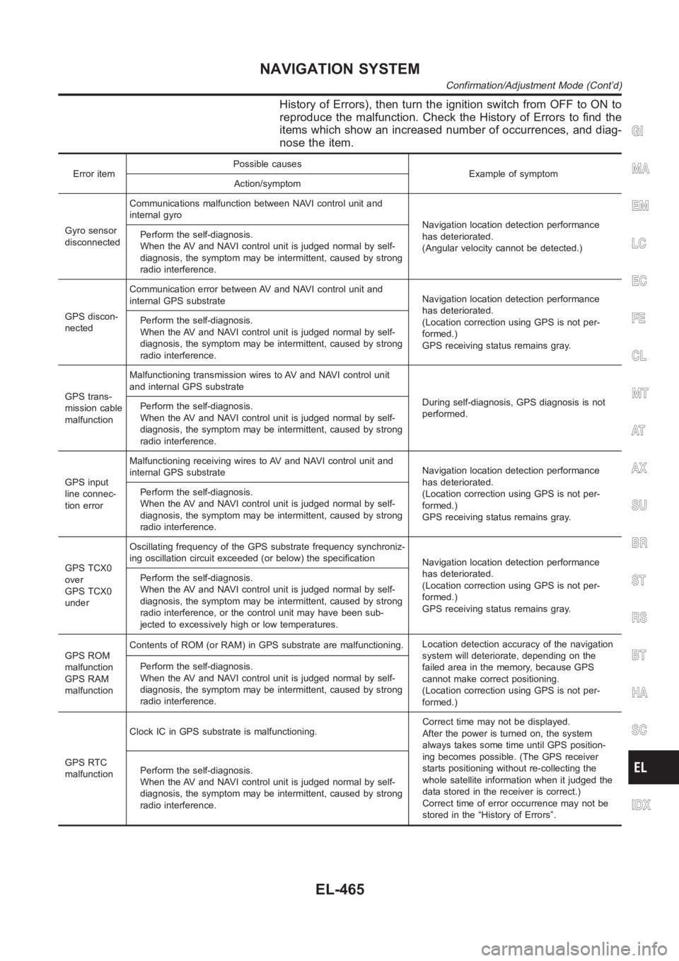
History of Errors), then turn the ignition switch from OFF to ON to
reproduce the malfunction. Check the History of Errors to find the
items which show an increased number of occurrences, and diag-
nose the item.
Error itemPossible causes
Example of symptom
Action/symptom
Gyro sensor
disconnectedCommunications malfunction between NAVI control unit and
internal gyro
Navigation location detection performance
has deteriorated.
(Angular velocity cannot be detected.) Perform the self-diagnosis.
When the AV and NAVI control unit is judged normal by self-
diagnosis, the symptom may be intermittent, caused by strong
radio interference.
GPS discon-
nectedCommunication error between AV and NAVI control unit and
internal GPS substrateNavigation location detection performance
has deteriorated.
(Location correction using GPS is not per-
formed.)
GPS receiving status remains gray. Perform the self-diagnosis.
When the AV and NAVI control unit is judged normal by self-
diagnosis, the symptom may be intermittent, caused by strong
radio interference.
GPS trans-
mission cable
malfunctionMalfunctioning transmission wires to AV and NAVI control unit
and internal GPS substrate
During self-diagnosis, GPS diagnosis is not
performed. Perform the self-diagnosis.
When the AV and NAVI control unit is judged normal by self-
diagnosis, the symptom may be intermittent, caused by strong
radio interference.
GPS input
line connec-
tion errorMalfunctioning receiving wires to AV and NAVI control unit and
internal GPS substrateNavigation location detection performance
has deteriorated.
(Location correction using GPS is not per-
formed.)
GPS receiving status remains gray. Perform the self-diagnosis.
When the AV and NAVI control unit is judged normal by self-
diagnosis, the symptom may be intermittent, caused by strong
radio interference.
GPS TCX0
over
GPS TCX0
underOscillating frequency of the GPS substrate frequency synchroniz-
ing oscillation circuit exceeded (or below) the specification
Navigation location detection performance
has deteriorated.
(Location correction using GPS is not per-
formed.)
GPS receiving status remains gray. Perform the self-diagnosis.
When the AV and NAVI control unit is judged normal by self-
diagnosis, the symptom may be intermittent, caused by strong
radio interference, or the control unit may have been sub-
jected to excessively high or low temperatures.
GPS ROM
malfunction
GPS RAM
malfunctionContents of ROM (or RAM) in GPS substrate are malfunctioning.Location detection accuracy of the navigation
system will deteriorate, depending on the
failed area in the memory, because GPS
cannot make correct positioning.
(Location correction using GPS is not per-
formed.) Perform the self-diagnosis.
When the AV and NAVI control unit is judged normal by self-
diagnosis, the symptom may be intermittent, caused by strong
radio interference.
GPS RTC
malfunctionClock IC in GPS substrate is malfunctioning.Correct time may not be displayed.
After the power is turned on, the system
always takes some time until GPS position-
ing becomes possible. (The GPS receiver
starts positioning without re-collecting the
whole satellite information when it judged the
data stored in the receiver is correct.)
Correct time of error occurrence may not be
stored in the “History of Errors”. Perform the self-diagnosis.
When the AV and NAVI control unit is judged normal by self-
diagnosis, the symptom may be intermittent, caused by strong
radio interference.
GI
MA
EM
LC
EC
FE
CL
MT
AT
AX
SU
BR
ST
RS
BT
HA
SC
IDX
NAVIGATION SYSTEM
Confirmation/Adjustment Mode (Cont’d)
EL-465