2003 NISSAN ALMERA N16 Fuel pressure sensor
[x] Cancel search: Fuel pressure sensorPage 8 of 3189
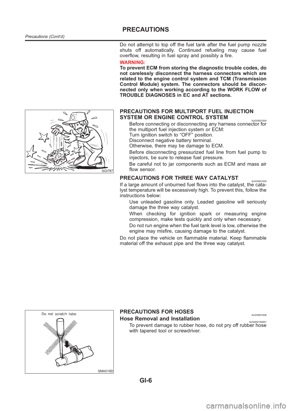
Do not attempt to top off the fuel tank after the fuel pump nozzle
shuts off automatically. Continued refueling may cause fuel
overflow, resulting in fuel spray and possibly a fire.
WARNING:
To prevent ECM from storing the diagnostic trouble codes, do
not carelessly disconnect the harness connectors which are
related to the engine control system and TCM (Transmission
Control Module) system. The connectors should be discon-
nected only when working according to the WORK FLOW of
TROUBLE DIAGNOSES in EC and AT sections.
SGI787
PRECAUTIONS FOR MULTIPORT FUEL INJECTION
SYSTEM OR ENGINE CONTROL SYSTEM
NJGI0001S04Before connecting or disconnecting any harness connector for
the multiport fuel injection system or ECM:
Turn ignition switch to “OFF” position.
Disconnect negative battery terminal.
Otherwise, there may be damage to ECM.
Before disconnecting pressurized fuel line from fuel pump to
injectors, be sure to release fuel pressure.
Be careful not to jar components such as ECM and mass air
flow sensor.
PRECAUTIONS FOR THREE WAY CATALYSTNJGI0001S05If a large amount of unburned fuel flows into the catalyst, the cata-
lyst temperature will be excessively high. To prevent this, follow the
instructions below:
Use unleaded gasoline only. Leaded gasoline will seriously
damage the three way catalyst.
When checking for ignition spark or measuring engine
compression, make tests quickly and only when necessary.
Do not run engine when the fuel tank level is low, otherwise the
engine may misfire, causing damage to the catalyst.
Do not place the vehicle on flammable material. Keep flammable
material off the exhaust pipe and the three way catalyst.
SMA019D
PRECAUTIONS FOR HOSESNJGI0001S06Hose Removal and InstallationNJGI0001S0601To prevent damage to rubber hose, do not pry off rubber hose
with tapered tool or screwdriver.
PRECAUTIONS
Precautions (Cont’d)
GI-6
Page 53 of 3189
NJGI0011
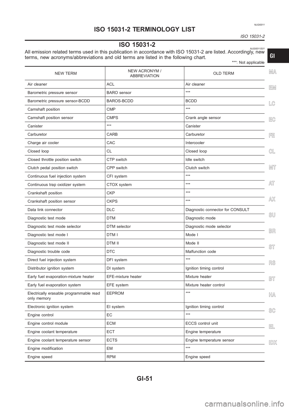
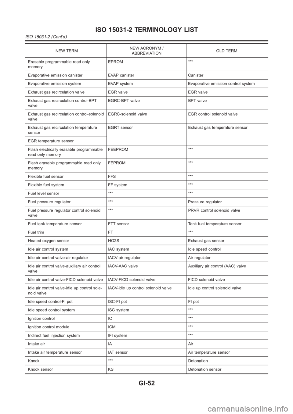
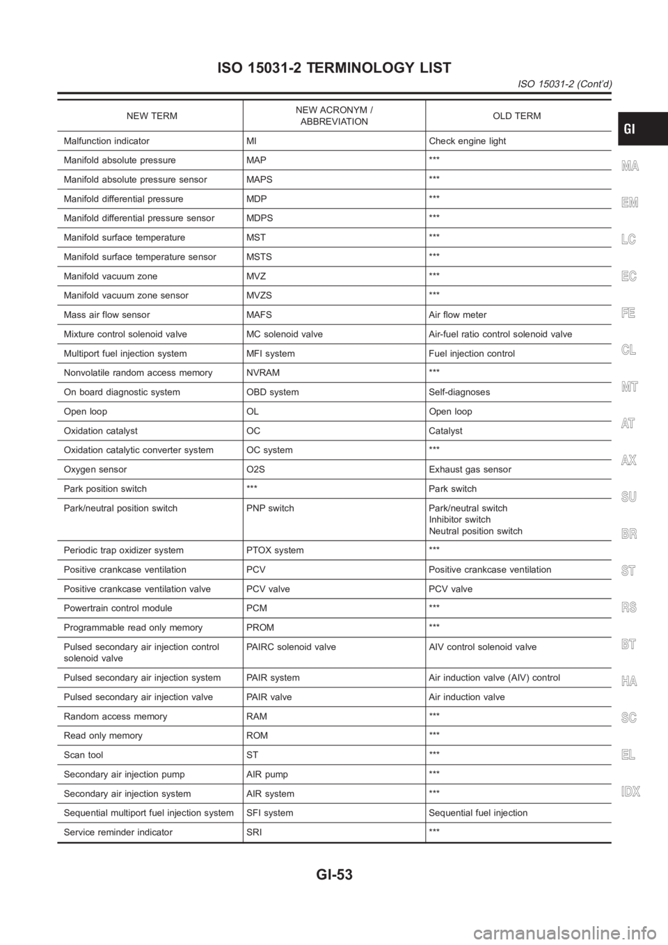
ISO 15031-2NJGI0011S01All emission related terms used in this publication in accordance with ISO15031-2 are listed. Accordingly, new
terms, new acronyms/abbreviations and old terms are listed in the following chart.
***: Not applicable
NEW TERMNEW ACRONYM /
ABBREVIATIONOLD TERM
Air cleaner ACL Air cleaner
Barometric pressure sensor BARO sensor ***
Barometric pressure sensor-BCDD BAROS-BCDD BCDD
Camshaft position CMP ***
Camshaft position sensor CMPS Crank angle sensor
Canister *** Canister
Carburetor CARB Carburetor
Charge air cooler CAC Intercooler
Closed loop CL Closed loop
Closed throttle position switch CTP switch Idle switch
Clutch pedal position switch CPP switch Clutch switch
Continuous fuel injection system CFI system ***
Continuous trap oxidizer system CTOX system ***
Crankshaft position CKP ***
Crankshaft position sensor CKPS ***
Data link connector DLC Diagnostic connector for CONSULT
Diagnostic test mode DTM Diagnostic mode
Diagnostic test mode selector DTM selector Diagnostic mode selector
Diagnostic test mode I DTM I Mode I
Diagnostic test mode II DTM II Mode II
Diagnostic trouble code DTC Malfunction code
Direct fuel injection system DFI system ***
Distributor ignition system DI system Ignition timing control
Early fuel evaporation-mixture heater EFE-mixture heater Mixture heater
Early fuel evaporation system EFE system Mixture heater control
Electrically erasable programmable read
only memoryEEPROM ***
Electronic ignition system EI system Ignition timing control
Engine control EC ***
Engine control module ECM ECCS control unit
Engine coolant temperature ECT Engine temperature
Engine coolant temperature sensor ECTS Engine temperature sensor
Engine modification EM ***
Engine speed RPM Engine speedMA
EM
LC
EC
FE
CL
MT
AT
AX
SU
BR
ST
RS
BT
HA
SC
EL
IDX
ISO 15031-2 TERMINOLOGY LIST
ISO 15031-2
GI-51
Page 54 of 3189
NEW TERMNEW ACRONYM /
ABBREVIATIONOLD TERM
Erasable programmable read only
memoryEPROM ***
Evaporative emission canister EVAP canister Canister
Evaporative emission system EVAP system Evaporative emission control system
Exhaust gas recirculation valve EGR valve EGR valve
Exhaust gas recirculation control-BPT
valveEGRC-BPT valve BPT valve
Exhaust gas recirculation control-solenoid
valveEGRC-solenoid valve EGR control solenoid valve
Exhaust gas recirculation temperature
sensorEGRT sensor Exhaust gas temperature sensor
EGR temperature sensor
Flash electrically erasable programmable
read only memoryFEEPROM ***
Flash erasable programmable read only
memoryFEPROM ***
Flexible fuel sensor FFS ***
Flexible fuel system FF system ***
Fuel level sensor *** ***
Fuel pressure regulator *** Pressure regulator
Fuel pressure regulator control solenoid
valve*** PRVR control solenoid valve
Fuel tank temperature sensor FTT sensor Tank fuel temperature sensor
Fuel trim FT ***
Heated oxygen sensor HO2S Exhaust gas sensor
Idle air control system IAC system Idle speed control
Idle air control valve-air regulator IACV-air regulator Air regulator
Idle air control valve-auxiliary air control
valveIACV-AAC valve Auxiliary air control (AAC) valve
Idle air control valve-FICD solenoid valve IACV-FICD solenoid valve FICDsolenoid valve
Idle air control valve-idle up control sole-
noid valveIACV-idle up control solenoid valve Idle up control solenoid valve
Idle speed control-FI pot ISC-FI pot FI pot
Idle speed control system ISC system ***
Ignition control IC ***
Ignition control module ICM ***
Indirect fuel injection system IFI system ***
Intake air IA Air
Intake air temperature sensor IAT sensor Air temperature sensor
Knock *** Detonation
Knock sensor KS Detonation sensor
ISO 15031-2 TERMINOLOGY LIST
ISO 15031-2 (Cont’d)
GI-52
Page 55 of 3189
NEW TERMNEW ACRONYM /
ABBREVIATIONOLD TERM
Malfunction indicator MI Check engine light
Manifold absolute pressure MAP ***
Manifold absolute pressure sensor MAPS ***
Manifold differential pressure MDP ***
Manifold differential pressure sensor MDPS ***
Manifold surface temperature MST ***
Manifold surface temperature sensor MSTS ***
Manifold vacuum zone MVZ ***
Manifold vacuum zone sensor MVZS ***
Mass air flow sensor MAFS Air flow meter
Mixture control solenoid valve MC solenoid valve Air-fuel ratio control solenoid valve
Multiport fuel injection system MFI system Fuel injection control
Nonvolatile random access memory NVRAM ***
On board diagnostic system OBD system Self-diagnoses
Open loop OL Open loop
Oxidation catalyst OC Catalyst
Oxidation catalytic converter system OC system ***
Oxygen sensor O2S Exhaust gas sensor
Park position switch *** Park switch
Park/neutral position switch PNP switch Park/neutral switch
Inhibitor switch
Neutral position switch
Periodic trap oxidizer system PTOX system ***
Positive crankcase ventilation PCV Positive crankcase ventilation
Positive crankcase ventilation valve PCV valve PCV valve
Powertrain control module PCM ***
Programmable read only memory PROM ***
Pulsed secondary air injection control
solenoid valvePAIRC solenoid valve AIV control solenoid valve
Pulsed secondary air injection system PAIR system Air induction valve (AIV) control
Pulsed secondary air injection valve PAIR valve Air induction valve
Random access memory RAM ***
Read only memory ROM ***
Scan tool ST ***
Secondary air injection pump AIR pump ***
Secondary air injection system AIR system ***
Sequential multiport fuel injection system SFI system Sequential fuel injection
Service reminder indicator SRI ***
MA
EM
LC
EC
FE
CL
MT
AT
AX
SU
BR
ST
RS
BT
HA
SC
EL
IDX
ISO 15031-2 TERMINOLOGY LIST
ISO 15031-2 (Cont’d)
GI-53
Page 146 of 3189
![NISSAN ALMERA N16 2003 Electronic Repair Manual EM-68
[QG]
ENGINE ASSEMBLY
WARNING:
●Position vehicle on a flat and solid surface.
●Place chocks at front and back of rear wheels.
●Do not remove engine until exhaust system has complete NISSAN ALMERA N16 2003 Electronic Repair Manual EM-68
[QG]
ENGINE ASSEMBLY
WARNING:
●Position vehicle on a flat and solid surface.
●Place chocks at front and back of rear wheels.
●Do not remove engine until exhaust system has complete](/manual-img/5/57350/w960_57350-145.png)
EM-68
[QG]
ENGINE ASSEMBLY
WARNING:
●Position vehicle on a flat and solid surface.
●Place chocks at front and back of rear wheels.
●Do not remove engine until exhaust system has completely cooled off, otherwise, you may burn
yourself and/or fire may break out in fuel line.
●Before disconnecting fuel hose, release pressure.
Refer to EC-34 (WITH EURO-OBD), EC-428 (WITHOUT EURO-OBD).
●Be sure to lift engine and transaxle in a safe manner.
●For engines not equipped with engine slingers, attach proper slingers and bolts described in
PARTS CATALOG.
CAUTION:
●When lifting engine, be sure to clear surrounding parts. Use special care near accelerator wire
casing, brake lines and brake master cylinder.
●When lifting the engine, always use engine slingers in a safe manner.
●When removing drive shaft, be careful not to damage grease seal of transaxle.
●Before separating engine and transaxle, remove crankshaft position sensor (POS) from the cylin-
der block assembly.
●Always be extra careful not to damage edge of crankshaft position sensor (POS), or signal plate
teeth.
Engine cannot be removed separately from transaxle. Remove engine with transaxle as an assembly.
REMOVAL
1. Drain coolant from radiator and cylinder block. Refer to LC-17, "Chacking Engine Coolant".
2. Remove coolant reservoir tank and bracket.
3. Drain engine oil.
4. Remove battery and battery tray.
5. Remove air cleaner and air duct.
6. Remove drive belts.
7. Remove alternator and air conditioner compressor from engine.
8. Remove power steering oil pump from engine and position aside.
Power steering oil pump does not need to be disconnected from power steering tubes.
9. Remove the following parts:
●RH and LH front tires
●Splash covers
●RH and LH brake caliper assemblies
Refer to BR-28,"Removal".
Brake hose does not need to be disconnected from brake
caliper assembly. Never depress brake pedal.
●RH & LH drive shaft. Refer to AX-11, "Removal".
When removing drive shaft, be careful not to damage
transaxle side grease seal.
●Disconnect control rod and support rod from transaxle. (M/T
models.)
Refer to MT-26, "Removal".
●Disconnect control cable from transaxle. (A/T models.)
Refer to AT-411, "Removal".
SEM174D
SEM109G
Page 331 of 3189
EC-1
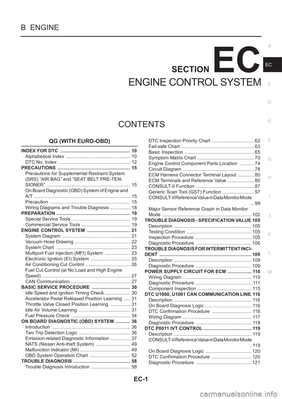
ENGINE CONTROL SYSTEM
B ENGINE
CONTENTS
C
D
E
F
G
H
I
J
K
L
M
SECTION
A
EC
ENGINE CONTROL SYSTEM
QG (WITH EURO-OBD)
INDEX FOR DTC ...................................................... 10
Alphabetical Index .................................................. 10
DTC No. Index ....................................................... 12
PRECAUTIONS ........................................................ 15
Precautions for Supplemental Restraint System
(SRS) “AIR BAG” and “SEAT BELT PRE-TEN-
SIONER” ................................................................ 15
On Board Diagnostic (OBD) System of Engine and
A/T .......................................................................... 15
Precaution .............................................................. 15
Wiring Diagrams and Trouble Diagnosis ................ 18
PREPARATION ......................................................... 19
Special Service Tools ............................................. 19
Commercial Service Tools ...................................... 19
ENGINE CONTROL SYSTEM .................................. 21
System Diagram ..................................................... 21
Vacuum Hose Drawing ........................................... 22
System Chart ......................................................... 23
Multiport Fuel Injection (MFI) System .................... 23
Electronic Ignition (EI) System ............................... 25
Air Conditioning Cut Control ................................... 26
Fuel Cut Control (at No Load and High Engine
Speed) .................................................................... 27
CAN Communication .............................................. 27
BASIC SERVICE PROCEDURE .............................. 30
Idle Speed and Ignition Timing Check .................... 30
Accelerator Pedal Released Position Learning ...... 31
Throttle Valve Closed Position Learning ................ 31
Idle Air Volume Learning ........................................ 31
Fuel Pressure Check .............................................. 34
ON BOARD DIAGNOSTIC (OBD) SYSTEM ............ 36
Introduction ............................................................ 36
Two Trip Detection Logic ........................................ 36
Emission-related Diagnostic Information ................ 37
NATS (Nissan Anti-theft System) ........................... 49
Malfunction Indicator (MI) ....................................... 49
OBD System Operation Chart ................................ 52
TROUBLE DIAGNOSIS ............................................ 58
Trouble Diagnosis Introduction ............................... 58DTC Inspection Priority Chart ................................. 62
Fail-safe Chart ........................................................ 63
Basic Inspection ..................................................... 65
Symptom Matrix Chart ............................................ 70
Engine Control Component Parts Location ............ 74
Circuit Diagram ....................................................... 78
ECM Harness Connector Terminal Layout ............. 80
ECM Terminals and Reference Value ..................
... 80
CONSULT-II Function ............................................. 87
Generic Scan Tool (GST) Function ......................... 97
CONSULT-II Reference Value in Data Monitor Mode
... 99
Major Sensor Reference Graph in Data Monitor
Mode .....................................................................102
TROUBLE DIAGNOSIS - SPECIFICATION VALUE .105
Description ............................................................105
Testing Condition ..................................................105
Inspection Procedure ............................................105
Diagnostic Procedure ...........................................106
TROUBLE DIAGNOSIS FOR INTERMITTENT INCI-
DENT .......................................................................109
Description ............................................................109
Diagnostic Procedure ...........................................109
POWER SUPPLY CIRCUIT FOR ECM ...................110
Wiring Diagram .....................................................110
Diagnostic Procedure ............................................111
Component Inspection ..........................................115
DTC U1000, U1001 CAN COMMUNICATION LINE .116
Description ............................................................116
On Board Diagnosis Logic ....................................116
DTC Confirmation Procedure ...............................116
Wiring Diagram .....................................................117
Diagnostic Procedure ...........................................118
DTC P0011 IVT CONTROL .....................................119
Description ............................................................119
CONSULT-II Reference Value in Data Monitor Mode
.119
On Board Diagnosis Logic ....................................120
DTC Confirmation Procedure ...............................120
Diagnostic Procedure ...........................................121
Page 335 of 3189
EC-5
C
D
E
F
G
H
I
J
K
L
M
ECA Wiring Diagram .................................................... 353
Diagnostic Procedure ........................................... 354
DTC P1706 PNP SWITCH ...................................... 356
Component Description ........................................ 356
CONSULT-II Reference Value in Data Monitor Mode
. 356
On Board Diagnosis Logic ................................... 356
DTC Confirmation Procedure ............................... 356
Overall Function Check ........................................ 357
Wiring Diagram .................................................... 358
Diagnostic Procedure ........................................... 359
DTC P1805 BRAKE SWITCH ................................ 360
Description ........................................................... 360
CONSULT-II Reference Value in Data Monitor Mode
. 360
On Board Diagnosis Logic ................................... 360
DTC Confirmation Procedure ............................... 360
Wiring Diagram .................................................... 361
Diagnostic Procedure ........................................... 362
Component Inspection ......................................... 364
IGNITION SIGNAL .................................................. 365
Component Description ........................................ 365
Wiring Diagram .................................................... 366
Diagnostic Procedure ........................................... 369
Component Inspection ......................................... 373
Removal and Installation ...................................... 374
INJECTOR CIRCUIT ............................................... 375
Component Description ........................................ 375
CONSULT-II Reference Value in Data Monitor Mode
. 375
Wiring Diagram .................................................... 376
Diagnostic Procedure ........................................... 377
Component Inspection ......................................... 380
Removal and Installation ...................................... 380
FUEL PUMP CIRCUIT ............................................ 381
Description ........................................................... 381
CONSULT-II Reference Value in Data Monitor Mode
. 381
Wiring Diagram .................................................... 382
Diagnostic Procedure ........................................... 383
Component Inspection ......................................... 385
Removal and Installation ...................................... 386
REFRIGERANT PRESSURE SENSOR ................. 387
Component Description ........................................ 387
Wiring Diagram .................................................... 388
Diagnostic Procedure ........................................... 389
Removal and Installation ...................................... 391
ELECTRICAL LOAD SIGNAL ................................ 392
Description ...................................................
........ 392
CONSULT-II Reference Value in Data Monitor Mode
. 392
Wiring Diagram .................................................... 393
Diagnostic Procedure ........................................... 394
MI & DATA LINK CONNECTORS .......................... 397
Wiring Diagram—LHD Models ............................. 397
Wiring Diagram—RHD Models ............................ 398
EVAPORATIVE EMISSION SYSTEM ..................... 399
Description ........................................................... 399
Component Inspection ......................................... 401POSITIVE CRANKCASE VENTILATION ...............402
Description ............................................................402
Component Inspection ..........................................402
SERVICE DATA AND SPECIFICATIONS (SDS) ....404
Fuel Pressure .......................................................404
Idle Speed and Ignition Timing .............................404
Calculated Load Value ..........................................404
Mass Air Flow Sensor ...........................................404
Intake Air Temperature Sensor .............................404
Engine Coolant Temperature Sensor ...................404
Heated Oxygen Sensor 1 Heater .........................404
Heated Oxygen sensor 2 Heater ..........................404
Crankshaft Position Sensor (POS) .......................404
Camshaft Position Sensor (PHASE) ....................404
Throttle Control Motor ...........................................405
Injector ..................................................................405
Fuel Pump ............................................................405
QG (WITHOUT EURO-OBD)
INDEX FOR DTC .....................................................406
Alphabetical Index ................................................406
DTC No. Index ......................................................407
PRECAUTIONS ......................................................409
Precautions for Supplemental Restraint System
(SRS) “AIR BAG” and “SEAT BELT PRE-TEN-
SIONER” ...............................................................409
On Board Diagnostic (OBD) System of Engine ....409
Precaution ............................................................409
Wiring Diagrams and Trouble Diagnosis ..............412
PREPARATION .......................................................413
Special Service Tools ...........................................413
Commercial Service Tools ....................................413
ENGINE CONTROL SYSTEM ................................415
System Diagram ...................................................415
Vacuum Hose Drawing .........................................416
System Chart ........................................................417
Multiport Fuel Injection (MFI) System ...................417
Electronic Ignition (EI) System .............................419
Air Conditioning Cut Control .................................420
Fuel Cut Control (at No Load and High Engine
Speed) ..................................................................421
CAN Communication ............................................421
BASIC SERVICE PROCEDURE .............................424
Idle Speed and Ignition Timing Check ..................424
Accelerator Pedal Released Position Learning ....425
Throttle Valve Closed Position Learning ...............425
Idle Air Volume Learning ......................................425
Fuel Pressure Check ............................................427
ON BOARD DIAGNOSTIC (OBD) SYSTEM ..........429
Introduction ...........................................................429
Two Trip Detection Logic ......................................429
Emission-related Diagnostic Information ..............429
NATS (Nissan Anti-theft System) .........................431
Malfunction Indicator (MI) .....................................432
TROUBLE DIAGNOSIS ..........................................436
Trouble Diagnosis Introduction .............................436
DTC Inspection Priority Chart ...............................440
Fail-safe Chart ......................................................441
Page 338 of 3189
EC-8
Wiring Diagram .....................................................625
Diagnostic Procedure ...........................................626
DTC P1805 BRAKE SWITCH .................................628
Description ............................................................628
CONSULT-II Reference Value in Data Monitor Mode
.628
On Board Diagnosis Logic ....................................628
DTC Confirmation Procedure ...............................628
Wiring Diagram .....................................................629
Diagnostic Procedure ...........................................630
Component Inspection ..........................................632
HO2S1 HEATER .....................................................633
Description ............................................................633
CONSULT-II Reference Value in Data Monitor Mode
.633
Wiring Diagram .....................................................634
Diagnostic Procedure ...........................................635
Component Inspection ..........................................637
Removal and Installation ......................................637
HO2S2 HEATER .....................................................638
Description ............................................................638
CONSULT-II Reference Value in Data Monitor Mode
.638
Wiring Diagram .....................................................639
Diagnostic Procedure ...........................................640
Component Inspection ..........................................642
Removal and Installation ......................................642
IAT SENSOR ...........................................................643
Component Description ........................................643
Wiring Diagram .....................................................644
Diagnostic Procedure ...........................................645
Component Inspection ..........................................646
Removal and Installation ......................................646
HO2S1 .....................................................................647
Component Description ........................................647
CONSULT-II Reference Value in Data Monitor Mode
.647
Wiring Diagram .....................................................648
Diagnostic Procedure ...........................................649
Component Inspection ..........................................652
Removal and Installation ......................................653
HO2S2 .....................................................................654
Component Description ........................................654
CONSULT-II Reference Value in Data Monitor Mode
.654
Wiring Diagram .....................................................655
Diagnostic Procedure ...........................................656
Component Inspection ..........................................658
Removal and Installation ......................................659
IGNITION SIGNAL ..................................................660
Component Description ........................................660
Wiring Diagram .....................................................661
Diagnostic Procedure ...........................................664
Component Inspection ..........................................668
Removal and Installation ......................................669
EVAP CANISTER PURGE VOLUME CONTROL
SOLENOID VALVE .................................................670
Description ............................................................670
CONSULT-II Reference Value in Data Monitor Mode .670
Wiring Diagram .....................................................671
Diagnostic Procedure ............................................673
Component Inspection ..........................................676
Removal and Installation .......................................676
VSS ..........................................................................677
Description ............................................................677
Diagnostic Procedure ............................................677
POWER STEERING PRESSURE SENSOR ...........678
Component Description ........................................678
CONSULT-II Reference Value in Data Monitor Mode
.678
Wiring Diagram .....................................................679
Diagnostic Procedure ............................................680
Component Inspection ..........................................682
IVT CONTROL SOLENOID VALVE ........................683
Description ............................................................683
CONSULT-II Reference Value in Data Monitor Mode
.683
Wiring Diagram .....................................................685
Diagnostic Procedure ............................................686
Component Inspection ..........................................688
Removal and Installation .......................................688
PNP SWITCH ..........................................................689
Component Description ........................................689
CONSULT-II Reference Value in Data Monitor Mode
.689
Wiring Diagram .....................................................690
Diagnostic Procedure ............................................691
INJECTOR CIRCUIT ...............................................693
Component Description ........................................693
CONSULT-II Reference Value in Data Monitor Mode
.693
Wiring Diagram .....................................................694
Diagnostic Procedure ............................................695
Component Inspection ..........................................698
Removal and Installation ......................................
.698
FUEL PUMP CIRCUIT .............................................699
Description ............................................................699
CONSULT-II Reference Value in Data Monitor Mode
.699
Wiring Diagram .....................................................700
Diagnostic Procedure ............................................701
Component Inspection ..........................................703
Removal and Installation .......................................704
REFRIGERANT PRESSURE SENSOR ..................705
Component Description ........................................705
Wiring Diagram .....................................................706
Diagnostic Procedure ............................................707
Removal and Installation .......................................709
ELECTRICAL LOAD SIGNAL ................................710
Description ............................................................710
CONSULT-II Reference Value in Data Monitor Mode
.710
Wiring Diagram .....................................................711
Diagnostic Procedure ............................................712
MI & DATA LINK CONNECTORS ...........................715
Wiring Diagram—LHD Models ..............................715
Wiring Diagram—RHD Models .............................716